
Universal Asynchronous Receiver/Transmitter (UART) is a method of serial communication allowing two different components on a device to talk to each other without the requirement of a clock. We consider UART in depth in this chapter as it is one of the most popular communication interfaces that has great significance in IoT security and penetration testing. There is also something known as Universal Synchronous/Asynchronous Receiver/Transmitter (USART), which transmits data both synchronously and asynchronously depending on the requirement; however, we have not seen a lot of devices using it. For that reason, we won’t be covering USART, and focus instead on UART.
We start by laying the foundation of serial communication and then move into the finer details of how to identify UART interfaces and interact with them. This chapter also serves as an introductory chapter for you to start your hardware exploitation journey if you have never done it before.
At the completion of this chapter, you will be able to open a device, look at the possible UART pins and identify the correct pinouts, and finally be able to communicate with the target device over UART. From a security standpoint, the ability to interact with UART will be useful to read a device’s debug logs, get unauthenticated root shell, bootloader access, and more.
Serial Communication
For any IoT or embedded device, the different components of a device need to interact with each other and exchange data. Serial communication and parallel communication are the two ways in which components on a device exchange data.
Serial communication protocol

Parallel communication protocol
That is the reason serial communication is a more common method of communication whenever we deal with embedded devices: Unlike parallel communication it requires just a single line to facilitate the data exchange.
Some of the popular serial communication channels you might have heard are Recommended Standard 232 (RS232), Universal Serial Bus (USB), PCI, High-Definition Multimedia Interface (HDMI), Ethernet, Serial Peripheral Interface (SPI), Inter-Integrated Circuit (I2C), Controller Area Network (CAN), and so on. The first serial communication channel used was RS232, which offered a data transmission rate of 20 kbps; then came the USB 1.0, offering rates of 12 Mbit/s; followed by USB 2.0, with a speed of 480 mbps; and finally the USB 3.0, with a speed of 5 Gbps—almost 10 times faster than its predecessor. It should also be noted that due to recent advancements in technology, serial communication is getting cheaper, faster, and more reliable.
Now that we have a basic idea of serial communication and some of its examples, let’s move on to UART, which is what we focus on in this chapter.
The What, Why, and How of UART
UART, as described earlier, is an asynchronous serial communication protocol used in many embedded and IoT devices. Asynchronous simply means that unlike a synchronous protocol (e.g., SPI), it does not have a clock that syncs for both the devices between which the communication taking place.
The data in the case of UART would be transferred without the need for an additional line of external clock (CLK). This is also why many other precautions are taken while transferring data asynchronously between devices over serial to minimize packet loss. We discuss baud rate, which will make this clearer to you, in later sections of this chapter.
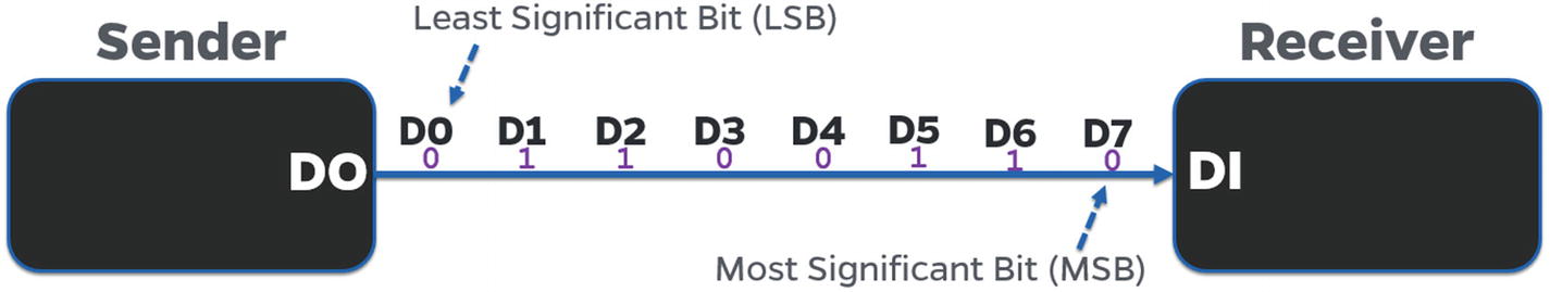
UART Data Packet
- 1.
Starting bit: The starting bit symbolizes that the UART data is going to be next. This is usually a low pulse (0) that you can view in the logic analyzer.
- 2.
Message: The actual message that is to be transferred as an 8-bit format. For example, if I have to transmit the value A (with the value 0x41 in hex) it would be transferred as 0, 1, 0, 0, 0, 0, 0, and 1 in the message.
- 3.
Parity bit: The parity bit is not that relevant in real-life scenarios (based on my experience), as I have not seen a lot of devices using it. A parity bit is used to perform error and data corruption checking by counting the number of high or low values in the message, and based on whether it’s an odd parity or an even parity, it would indicate that the data are not correct. Remember that the parity bit is only used for data corruption checking and validation, and not actual correction.
- 4.
Stop bit: The final bit that symbolizes that the message has now completed transmission. This is usually done by a high pulse (1), but could also be done by more than one high pulse, depending on the configuration the device developer uses.

UART packet structure
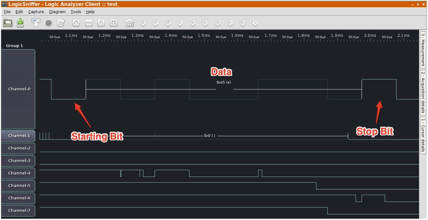
UART packet structure analysis by a logic analyzer
Type of UART Ports
A UART port could either be hardware based or software based. To give you an example, Atmel’s microcontrollers AT89S52 and ATMEGA328 have just one hardware serial port. If it is required, a user is free to emulate more software UART ports on specific general purpose input/output (GPIOs). In contrast, microcontrollers like LPC1768 and ATMEGA2560 have multiple hardware UART ports, all of which could be used to perform UART-based analysis and exploitation.
Even though we are looking at devices from a security standpoint, one of the things to understand is the technologies that we are discussing—UART, JTAG, SPI, I2C, and so on; even though they can be used for security research and exploitation purposes, their primary function is to either facilitate component-to-component communication or provide additional functionality to the developer.
Software-based UARTs are required when there is a need to connect multiple devices via UART to a given device that only has limited sets of hardware UART pins. This also gives the flexibility to the user to use the GPIO pins as UART when required and use it for another purpose at a later point in time.
We won’t be covering software-based UART in detail because in real-world commercial devices, we won’t usually require multiple UART ports and we won’t have the ability (or access) to program the GPIOs to emulate UART, or simply because there are not enough GPIO pins on our target device that could be emulated.
Note
In this book, I use the terms port, pins, and pads interchangeably.
Baud Rate
Working with UART and discussing the nonrequirement of CLK brings us to the concept of baud rate, which specifies the rate at which data are transferred between devices, or more appropriately, the number of bits per second that are being transferred. This is required because there is no clock line in the case of UART communication, so both the communications need to have a mutual understanding of the speed of data communication. That is why both the components will agree on a single baud rate during the entire UART data exchange process.
During any of the UART exploitation that you perform in your security research journey, one of the initial steps will always be to identify the baud rate of the target device. This can be done in a number of ways, such as looking at the output while interfacing over serial at a given baud rate, and if the data appears to be not readable, moving to the next baud rate. To make things easier, there are a couple of standard values of baud rate to which you will find most devices adhering. The common baud rates are 9600, 38400, 19200, 57600, and 115200. Having said that, a device developer is free to choose a custom value for baud rate.
To identify the correct baud rate using the approach just mentioned, we use a script written by Craig Heffner, called baudrate.py available at https://github.com/devttys0/baudrate/blob/master/baudrate.py . This script allows us to change baud rates while maintaining a serial connection, to easily identify what the correct value of the baud rate is by looking at the output and visually inspecting which baud rate gives readable output.
Before connecting to a device over serial and identifying baud rate values, let’s first go through the hardware connections that need to be made to interact with the target device over UART and exploit the device.
Connections for UART Exploitation
To perform a UART-based exploitation, we need two primary components: the target device and a device that could emulate a serial connection to access the end device, so that the target device is able to interact with our system.
Edimax 3116W IP camera (feel free to choose from any other vulnerable device that has a UART interface).
Attify Badge (you could also use a normal USB-TTL or BusPirate).
Multimeter.
Headers (in case you would like to solder to the empty pads to be able to connect the jumpers firmly).
Three jumper wires.
To make the connections, we first need to identify where the UART port on the device is, or what the UART pins are. This can be done by a visual inspection of the internal device components and looking for three or four pins or pads close to each other. That is an easy way to find UART pins, but in some cases, you might also encounter devices that have the UART pins scattered across the board and not together at a single place. Figures 4-5 through Figures 4-7 are references to help you identify UART ports in your target device.
CASE 1 —EDIMAX 3116W
UART ports in Edimax 3116W
CASE 2 —TP-LINK MR3020

UART ports in TP Link MR3020
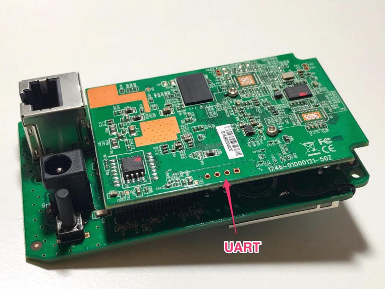
CASE 3 —HUAWEI HG533

UART ports in Huawei HG533 (Source: jcjc-dev.com)
- 1.
Transmit (Tx): Transmits data from the device to the other end.
- 2.
Receive (Rx): Receives data from the other end to the device.
- 3.
Ground (GND): Ground reference pin.
- 4.
Voltage (Vcc): Voltage, usually either 3.3V or 5V.
To find all these pins, we use a multimeter that helps us identify the pins based on either the continuity test (for GND) or by looking at the voltage difference (for the remaining three pins).
A multimeter is a combination of a voltmeter and ammeter, which means it allows us to look at both the value of voltage and the value of current during the analysis. This is extremely useful. Even though most of the time we will be simply looking at the voltage value, in some cases, you might be required to look at the value of current flowing between two different pins to perform further analysis. Let’s get started.
Identifying UART Pinouts
As mentioned earlier, a multimeter is a device that can measure voltage (V), current (A), and resistance (R), thus the name multimeter—a combination of both voltmeter and ammeter.
We will keep the target device powered off initially, as we are going to perform a continuity test to identify ground.

Multimeter connections
- 1.
Place the black probe on a ground surface; this could be any metallic surface (e.g., the Ethernet shield of the device) or the GND of the Attify Badge. Place the red probe on each of the four pads individually. Repeat with the other pads until you hear a beep. The place where you hear a beep is the ground pin on the target device. Make sure your device is turned off. One of the other things to note here is that there will be a number of ground pins or pads on the target device, but we are only concerned with the GND in the UART pin pair.
Ensure that your multimeter is as shown in Figure 4-9.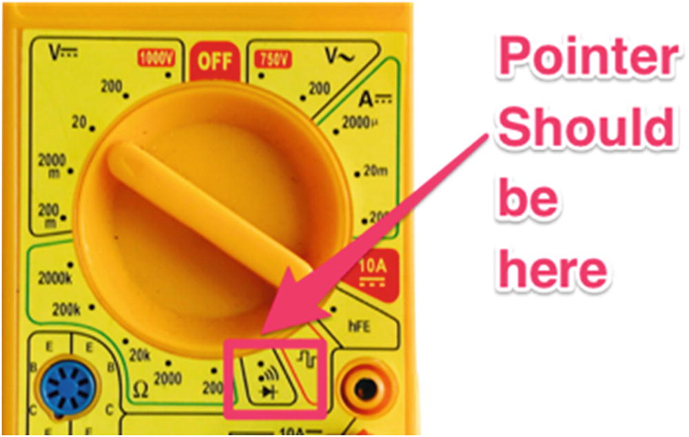 Figure 4-9
Multimeter setting
- 2.
Put the multimeter pointer back to the V–20 position, as we are now going to measure voltage. Keep the black probe to GND and move your red probe over other pins of the UART (other than the GND). Power cycle the device and turn it on. The place where you see a constant high voltage is the Vcc pin. If you miss it on the first try, power cycle it again.
- 3.
Reboot the device again and measure the voltage between the remaining pads and GND. Due to the huge amount of data transfer initially during bootup, you will notice a huge fluctuation in the voltage value during the initial 10 to 15 seconds. This pin will be the Tx pin.
- 4.
Rx can be determined by the pin having the lowest voltage during the entire process, with the black probe connected to the GND of the Attify Badge. Alternatively, you will usually have only a single pin left by this step, which will be Rx.
By now you should have been able to successfully identify all the different pins present in the UART of your target device. Make note of these values because we are going to be using this while making our connections.
Note
You could also analyze these values by hooking up a logic analyzer and looking at the values that are being passed.
Introduction to Attify Badge
One of the tools that is an absolute necessity in an IoT pentester’s arsenal is a device capable of working with different hardware communication protocols. The tool that we are going to use for all our hardware exploitation needs is Attify Badge.
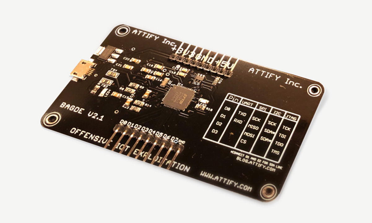
Attify Badge tool for performing hardware exploitation

Attify Badge pinouts
Attify Badge Pinouts
Pin | UART | SPI | I2C | JTAG |
|---|---|---|---|---|
D0 | TX | SCK | SCK | TCK |
D1 | RX | MISO | SDA* | TDI |
D2 | MOSI | SDA* | TDO | |
D3 | CS | TMS |
To connect the Attify Badge to our system, we will need to use a micro USB cable. If you are using AttifyOS or running on Mac OS, you do not need any special tools to work with Attify Badge. However, on Windows, you might need to download the FTDI driver available from https://www.ftdichip.com/FTDrivers.htm to get the device working with your system.
To verify it is has successfully connected, you can run lsusb (on a Linux machine), which would show you a device listed as Future Devices Technology International, which is the Attify Badge.
Making Final Connections
Once you have identified the pinouts of the device, the next step will be to connect the device’s UART pins to the Attify Badge’s UART.
Connections for Target IoT Device to Attify Badge for UART Exploitation
Pin on IP camera | Connected to the Attify Badge |
|---|---|
Tx | D1 (as D1 is the Rx for badge) |
Rx | D0 (as D0 is the Tx for badge) |
GND | GND |
Vcc | Not connected |
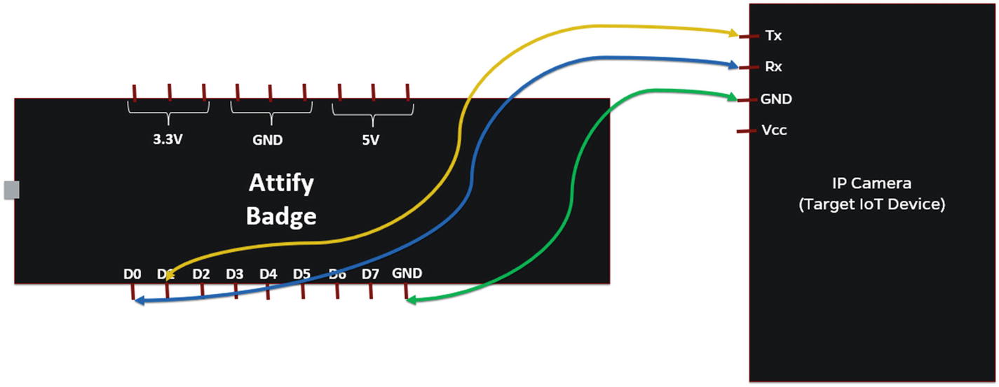
Connections to connect Attify Badge to target IoT device for UART
That is all the connections required to perform the UART-based analysis and exploitation.
Identifying Baud Rate
Baud rate connections
You might see gibberish data at first as soon as the IP camera boots up because the device might not be configured to transfer data at the default value baudrate.py chooses. Use the up and down arrow keys to move between different values of the baud rate. The baud rate where you can see readable characters is the correct baud rate of the device. In our case, the correct baud rate is 38400. If you don’t see any data at all, reboot the device and make sure that the connections are right, with the correct values of Tx and Rx.
That is how to identify the baud rate of any target device.
Interacting with the Device
Once we have identified the correct baud rate, the next step is to interact with the device over UART. This could either be done through the baudrate.py script itself, by pressing Ctrl+C once it detects the correct baud rate, lauching a utility called minicom. The other way is to manually launch a utility, such as screen or minicom, with the identified configurations.
- 1.
Baud rate of the device: 38400
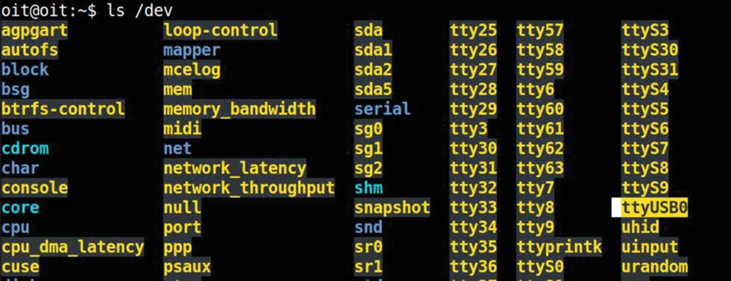
- 2.
COM port used by the Attify Badge: /dev/ttyUSB0Let’s go ahead and launch screen with the previously given values.
sudo screen /dev/ttyUSB0 38400
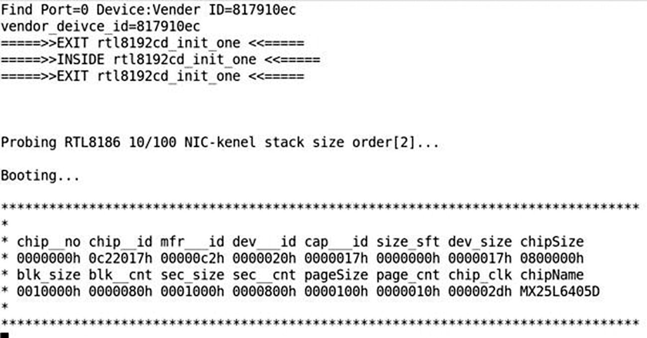
Debug logs from device bootup

Root shell on the device
Congratulations! You now have a complete unauthenticated root shell to the device. You can perform several things here, such as analyzing the device’s file system, modifying some of the configurations, identifying hidden sensitive values, dumping the firmware, and so on.

Root shell using Attify Badge tool
During your IoT security research journey, you will be surprised by the number of real-world commercial devices that grant you unauthenticated root access to the device.
Make sure the connections are correct; that is, Tx from one device goes to the Rx of others and Rx of the other goes to Tx.
GND is connected to other device’s GND.
Vcc is not connected to anything.
The value of baud rate is correctly identified, otherwise you might see nonreadable data.
Make sure you use a proper voltage converter when using a 3.3V serial device to a 5V serial device or other voltage levels.
Conclusion
In this chapter, we had a look at how we can get started performing embedded device exploitation for IoT devices using serial communication, and specifically, UART.
UART will be useful for you at a number of places, and you’ll often encounter devices with no protection, giving you access to an unauthenticated root shell over UART.
I would highly recommend you try additional activities once you have UART access, such as interacting with the bootloader, modifying certain values in configurations, figuring out ways to dump firmware over UART, and so on.