Chapter 22 Designing a Network Infrastructure
Designing a network infrastructure is one of those topics that is subject to opinion. Previous experience, comfort level with different technologies, and feature likes and dislikes will all play a part in the outcome of a design. Although many solutions may exist, the ultimate goal is a reliable, manageable, cost-effective infrastructure that meets or exceeds the requirements of the project.
A very important aspect of designing, not only with the Firewall Services Module (FWSM) but with all networking components, is to understand the features and capabilities of the hardware and software.
One of the keys to success is to “keep it simple.” This makes it easier to understand, configure, maintain, and troubleshoot.
For network design, consider the following three-step process as you plan and implement the design:
Step 1 | Determine design considerations. |
Step 2 | Determine deployment options. |
Step 3 | Determine where or how to logically place the FWSM. |
Determining Design Considerations
In the process of a network design, the first step is to determine exactly what you are attempting to accomplish and document that information. Yes, this should go without mentioning, but most people miss the documentation part. Why is the documentation so important? It sets expectations for all parties involved and minimizes any negative impact in your direction. This gives you documentation to refer to when “scope creep” becomes an issue, and it provides you with ammunition against the “You said it would support that!” comment.
A security policy is imperative for security designs. This will define the constraints that need to be adhered to. If you do not already have a security policy, you need one now! Creating security policies is beyond the scope of this book; however, for additional information, see the Cisco Network Security Policy: Best Practices White Paper, Document ID: 13601.
Documenting the Process
Documenting the process is one of the most important aspects of creating a network design because it provides a record of the requirements, the scope of the project, and so on. This document should be very clearly written to avoid ambiguity and will provide a foundation for the entire plan.
The project documentation should contain information such as the following:
• What is the end goal?: A general mission/project statement needs to define what you are attempting to accomplish. This could be something like “Protecting the Internet facing web server.”
• What resources need to be secured?: Define the exact devices and IP addresses.
• What are the applications?: List all the IP TCP/UDP port numbers.
• Is application inspection required?: Refer to Chapter 14, “Filtering,” for supported application inspection engines.
• Is multicast needed to support this application?: If multicast is necessary, configuring the FWSM in transparent mode may be beneficial.
• Are other protocols needed?: Hopefully not, but in the rare case when they are, it would be necessary to configure the FWSM in transparent mode. Recall also that non-IP protocols will not be inspected.
• Who is allowed to have access?: Are there specific devices that can be defined by IP address?
• Will the FWSM need to authenticate access?: If the FWSM needs to perform authentication, do you have the appropriate devices to perform this task? Refer to Chapter 10, “AAA Configuration,” for additional information.
• What are the bandwidth/performance requirements?: Is a single FWSM capable of supporting the application, or will multiple FWSMs be required?
• Are multiple contexts necessary or useful?: Multiple contexts are very useful if you need a combination of routed and transparent firewalls or you have multiple customers with different security policies.
• Is a secondary firewall needed for failover?: If high availability is required, having a secondary FWSM is imperative. See Chapter 13, “Understanding Application Protocol Inspection,” for details.
• Who is managing the FWSM or context?: If you have multiple customers, multiple contexts will allow them to manage their own FWSM instance.
• Does this project fall under the constraints of the security policy?: If not, you need to have the security policy changed or change the scope of the project. Good luck!
This is not an all-inclusive list, but it is a good baseline.
Creating a document outlining the aspects of the design will provide everyone involved with a central record from which to receive information. Having this type of document with well-defined criteria will certainly help minimize scope creep, unnecessary changes, and so on.
Determining Deployment Options
After collecting and compiling the information from Step 1, Step 2 is to determine the deployment options:
• Should the FWSM be in single-context mode?: If a single organization maintains control over the FWSM and logical separation of multiple firewalls is not required, the answer could be yes. Another benefit of single-context mode is a greater rule limit. Refer to Chapter 2, “Overview of the Firewall Services Module,” for details.
Native multicast and routing protocols are also supported in single-context routed mode. See Chapter 16, “Multicast,” and Chapter 17, “Asymmetric Routing,” for additional details.
• Should the FWSM be in multi-context mode?: If there are multiple organizations, or separation of applications/services are required, multi-context mode may be a good solution. Remember that in multi-context mode the rule limit is reduced. Refer to Chapter 2 for details.
There is also a license cost if you need more than two contexts.
• Should the FWSM be configured in routed mode?: Routed mode is a great solution if a need exists for multiple interfaces. For example, you may require inside, outside, and DMZ interfaces, which are possible only in routed mode.
If you are using multi-context mode, the only routing protocol that supports multiple contexts is Border Gateway Protocol (BGP) stub. For deployment considerations, see Chapter 17.
• Should the FWSM be configured in transparent mode?: Transparent mode supports only two interfaces, but up to eight bridge groups are allowed per context.
No IP readdressing is required.
Routing protocols (except IS-IS) can transparently pass through the FWSM.
• What about high availability?: Consider using multiple chassis with multiple firewalls and inter-chassis failover. See Chapter 13 for details.
• How are access lists created?: Based on the information gathered for who needs access, you can use a couple of options. The best option is to create a very limited rule-set to allow only specific traffic through. Then use noise-level detection (users complaining about not being able to access the service) and modify the access list accordingly.
The other option is to open the rule-set wider than necessary, monitor access to the resource, and then shrink the access list to specific traffic. This can be dangerous because interruptions in service make it difficult to troubleshoot, and many times the access lists are not restrictive enough to keep out unwanted guests.
You can choose from several deployment options, and some of these may be mutually exclusive. For example, you might be required to operate in transparent mode but need multiple interfaces. Applying the design considerations to the deployment options is the difficult part—and why you get paid the “big bucks.” Thorough knowledge of the FWSM and the capabilities and limitations will significantly improve your success.
Determining Placement
Step 3 is where or how to logically place the FWSM. Given the flexibility in the configuration of the host-chassis and the FWSM, you can choose from many deployment options.
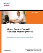
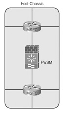
• Single-context routed-mode inside/outside: This option allows the FWSM to participate in the routing process and has the capability to support multiple interfaces.
From a security perspective, having another process running creates additional vulnerabilities. Moving the routing process to the multilayer switch feature card (MSFC) or other router improves the security of the FWSM. Figure 22-1 illustrates how the FWSM can be placed in regard to the routing process on the host-chassis, either on the inside or the outside.
Figure 22-1 Single-Context Routed-Mode Inside/Outside
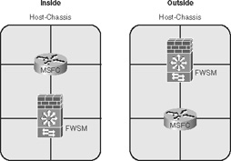
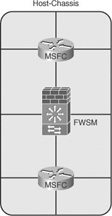
• Single-context transparent-mode inside/outside: This option limits the number of interfaces to two, but does not require IP address changes and allows the capability to pass routing information. Figure 22-2 illustrates how the routing process on the host-chassis can be used with the FWSM, with the FWSM placed on either the inside or the outside.
Figure 22-2 Single-Context Transparent-Mode Inside/Outside
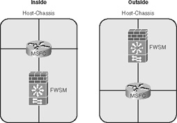
• Multiple-context routed-mode inside/outside: This option allows the routed context to have multiple interfaces, but remember that in multi-context mode, static routing and BGP stub are the only supported routing protocols. Refer to Chapter 9, “Configuring Routing Protocols,” for additional information. Figure 22-3 illustrates how multiple contexts can be used in conjunction with the routing process of the host-chassis.
Figure 22-3 Multiple-Context Routed-Mode Inside/Outside
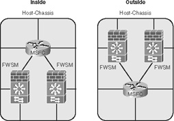
• Multi-context transparent-mode inside/outside: This option provides the capability to pass routing protocols between Layer 3 devices and does not require IP address changes. Figure 22-4 illustrates how the FWSM can support multiple contexts in transparent mode, either being placed on the inside or the outside of the routing process on the host-chassis.
Figure 22-4 Multi-Context Transparent-Mode Inside/Outside

• FWSM-sandwich in routed-mode: This functionality significantly leverages the investment in the host-chassis by creating multiple virtual routing instances. Figure 22-5 illustrates how virtualized routing processes on the host-chassis can be placed on the inside and the outside of the FWSM with the FWSM in routed-mode.
Figure 22-5 Multiple-Context Transparent-Mode Inside/Outside
• FWSM-sandwich in transparent-mode: This functionality significantly leverages the investment in the host-chassis by creating multiple virtual routing instances. Transparent mode allows the capability to establish routing adjacencies between virtual routing instances. This configuration now uses routing information to determine whether any link failures occur and minimizes any impact of Spanning Tree. Figure 22-6 illustrates how virtualized routing processes on the host-chassis can be placed on the inside and the outside of the FWSM with the FWSM in transparent-mode.
Figure 22-6 Multiple-Context Transparent-Mode Inside/Outside
• Shared interfaces in routed-mode: Due to packet classification, the only configuration of shared interfaces that should be used is a shared outside deployment model. A shared inside deployment model could be used but requires static NAT translations for the destination addresses, which can be used only in limited situations.
Sharing the inside interface or multiple interfaces should be avoided. Figure 22-7 illustrates deployment methods of which a single shared interface—for example, the outside—would be the only recommended approach.
Figure 22-7 Shared Interfaces Routed-Mode
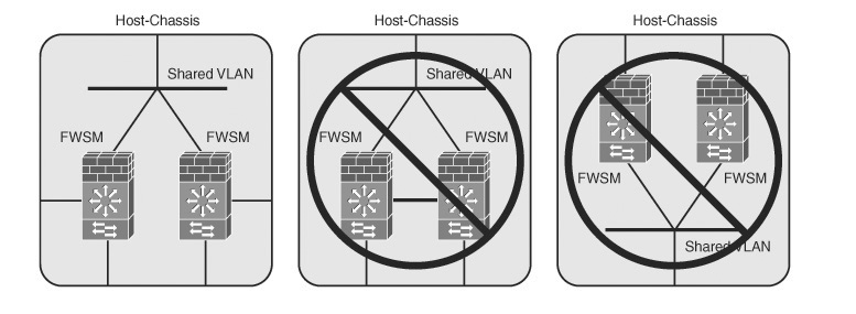
• FWSM only: The FWSM can be used without any interaction from the MSFC, as shown in Figure 22-7. Although this is supported, you are paying for valuable hardware (MSFC) that is not being used.
Many options exist for the placement of the FWSM in regard to the routing process or processes on the host-chassis. Examples in this section demonstrate how flexible the placement can actually be; it’s up to you to determine what the appropriate deployment model will look like to meet your documented project requirements.
Working with FWSM and the Enterprise Perimeter
Because the FWSM and the host-chassis are integrated devices, greater care must be taken when placing any interfaces on untrusted networks. If either the FWSM or host-chassis are compromised, the results will be disastrous, with the potential for compromised devices, the loss of information, denial-of-service, and so on. If you find yourself in this situation, you might have wished you read Chapter 20, “Preventing Network Attacks.” The recommended placement is to locate the FWSM interfaces on the untrusted networks and not those of the MSFC. This configuration would be the outside model referred to in Figures 22-1, 22-2, 22-3, and 22-4. Because the FWSM is a true security device, it has a better capability of fending off malicious attacks than the routing process of the host-chassis. It also provides better protection against inadvertent mistakes—for example, placing an FWSM interface in the wrong VLAN—that may occur during configuration changes because of the fail-closed nature of a firewall in contrast to the fail-open nature of a router.
Also, be sure when configuring the VLAN interface that connects to the untrusted network that it has been “hard-set” for that specific VLAN and will not trunk! This prevents the possibility of bypassing the FWSM on a separate VLAN. Follow the practices for securing the host-chassis outlined in Chapter 6, “Configuring and Securing the 6500/7600 Chassis.”
When considering the placement of the FWSM in regard to the routing process of the host-chassis, the FWSM should always be closest to the most untrusted network(s). If the FWSM is placed in a location without a trusted network connection, consider not using any routing process on the host-chassis to minimize the potential compromise of the host-chassis.
FWSM in the Datacenter
With the number of new applications that are being developed, the requirement to keep them secure and the expectation that they are always available can be difficult to accomplish. Having the flexibility to support these applications while providing uptime is paramount to providing services to your customers.
The primary considerations for deploying an FWSM in the datacenter are throughput, flexibility, availability, and support for virtualization.
Throughput
Throughput requirements continue to grow as new applications are added and as additional devices require those resources. Up to four FWSMs can be installed in the host-chassis to maximize throughput. Remember from Chapter 2 that the connection from the FWSM to the host-chassis is a 6-gigabit EtherChannel. This means that a single flow can reach a maximum of only 1 Gbps because of the way in which flows are distributed across the EtherChannel.
Flexibility
Having the flexibility to operate the FWSM in multiple-context mode allows the capability to quickly add contexts to support new applications. Applications associated with particular contexts can also be given additional resources. Refer to the section titled “Understanding Resource Management” in Chapter 5.
Configuring contexts in transparent mode allows you to support dynamic routing protocols for Layer 3 failover and will also easily support multicast or non-IP traffic if the requirement arises.
Availability
High availability using a redundant FWSM in multiple host-chassis allows access to the datacenter resources in the event of a FWSM or host-chassis failure.
Using the FWSM to provide firewall services to applications within the datacenter is one of the most common implementations of the FWSM. Given the performance capability, the high availability using redundant FWSMs, the small footprint and low power requirements, the flexibility of deployment using routed-mode or transparent-mode, and the capability to virtualize contexts makes the FWSM an excellent choice for datacenter deployments.
Supporting Virtualized Networks
Many organizations have realized the benefits of traffic separation or network virtualization through the use of multiprotocol label switching (MPLS), multiple virtual routing and forwarding (multi-VRF), multitopology routing (MTR), virtual private LAN services (VPLS), and so on. These technologies leverage a single physical infrastructure while providing a logical mechanism for traffic separation. Rather than installing a unique physical firewall per virtual network, you can configure the FWSM to support multiple contexts using a combination of routed or transparent mode. Because this can be accomplished in a single chassis, configuration changes do not require physical rewiring.
The host-chassis can support multiple routing instances (contexts) and bridging contexts (VLANs). Consider the host-chassis as a whiteboard, and you have the ability to connect routing, bridging, or firewall instances in many configurations. Using a routing context between FWSM instances allows you to overcome the limitation of cascading contexts, which is not a supported configuration.
Figure 22-8 illustrates the capabilities of virtualizing the FWSM, LANs, and routing processes on the host-chassis. Although this probably wouldn’t be a configuration you would want to manage, it does show the tremendous flexibility of the solution. Example 22-1 shows the configuration associated with the illustration in Figure 22-8.
Figure 22-8 Example of Multiple Routing and Firewall Instances
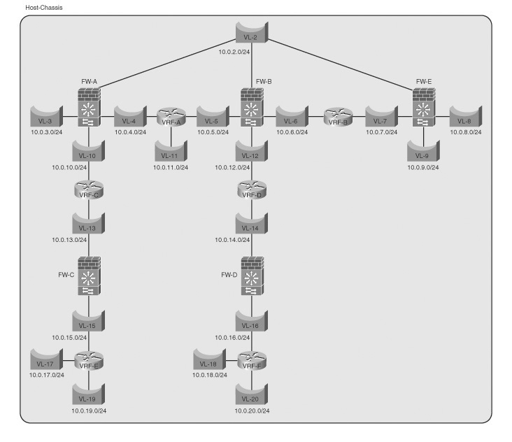
Exampl 22-1 Configuring Multiple Routing and Firewall Instances
The configuration in Example 22-1 would not be something you would want to implement in a production environment, unless you need job security, but it does give you an idea of the flexibility of the host-chassis and FWSM.
Virtualization of FWSM contexts, LANs, and routing processes gives you tremendous flexibility in modifying existing services and deploying new services, especially because the entire previous example didn’t require any physical cabling!
Summary
When designing a secure network infrastructure, the better understanding that you have of the operation and capabilities of all the devices that will be included in the solution will dramatically improve the success and security of the entire design. Take a methodical approach by determining the design requirements and considering the deployment options and placement of the FWSM. Also, don’t avoid the documentation process as many of us do; this could be a life saver, or at least a job saver. Finally, to make the solution manageable, use the Keep It Simple method of design.
Reference
Cisco Network Security Policy: Best Practices White Paper, Document ID: 13601