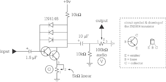
This circuit, Figure 16-3, is another one that’s simple enough to build dead-bug style. Start by joining the two transistors, as shown in the schematic (the diagram on the left illustrates how the legs in the schematic map to the legs on a real-life transistor).
Note
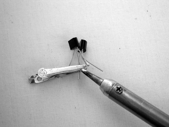
Transistors are a little easier to damage with heat than other components we’ve used; as you solder them, attach an alligator clip between the solder point and the body of the component as in Figure 16-4; this will act as a heat sink.
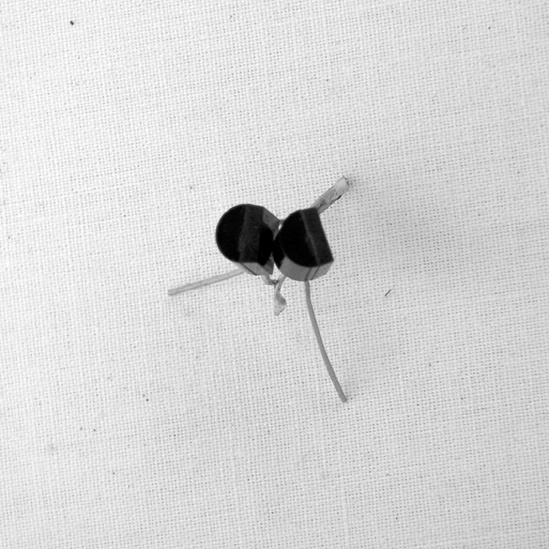
Put one transistor behind the other, like spooning lovers. Twist and solder together both transistors’ collectors, then twist the rear transistor’s emitter to the front transistor’s base, solder these, and trim them down to 1/4″ long. (This is shown in Figure 16-5; if the terms are confusing, refer to the inset on Figure 16-3. For more on what transistors actually do, flip to the appendix or to the Jitterbug’s How It Works in How It Works.) Notice that the final result is that the two now function as one big transistor with a single base, emitter, and collector. This configuration is called a Darlington pair; it was invented in 1953 by Sydney Darlington at Bell Labs as a way of addressing limitations in the quality and consistency of the earliest transistors. It’s just a happy accident that his configuration can also be used to rock the house down.
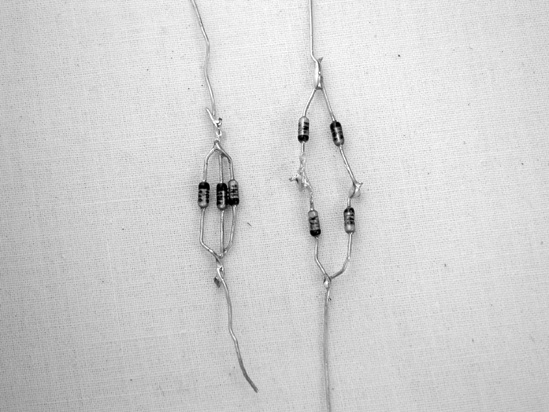
Next, build the anti-parallel diode array. This will provide the distortion. Diodes are also a little heat sensitive, so play it safe and use a heat sink. As is shown on the left side of Figure 16-6, solder the three diodes in parallel with the stripes (negative legs) of two pointing one direction and the stripe of the third pointing the other.
Solder this diode array to the transistors so it connects the collector and base of the transistor pair; note that the side of the array with two negative legs should be toward the transistor pair’s base.
You may want to consider using alligator clips to connect these to the circuit, rather than soldering them in now, so you can experiment. More diodes increase distortion but decrease the final volume. Symmetrical diodes (e.g., a total of four, two in each direction, as on the right side of Figure 16-6) will bring out metallic, clangy, gong-like overtones (a bit like a ring modulator effect—which makes sense, since a traditional ring modulator gets its sound by mixing two signals through just such an arrangement of diodes). This will be more pronounced if you accentuate the high end by swapping the 1.5 μF input capacitor in Step 9 with a much smaller value, like 0.022 μF. You can also use totally different types of diodes (like germanium diodes or even LEDs—they won’t light up in this circuit, but they will add their own distinctive, tamer roar). You can even get away with just a single diode, connected with its positive leg to the collector and negative leg to the base.
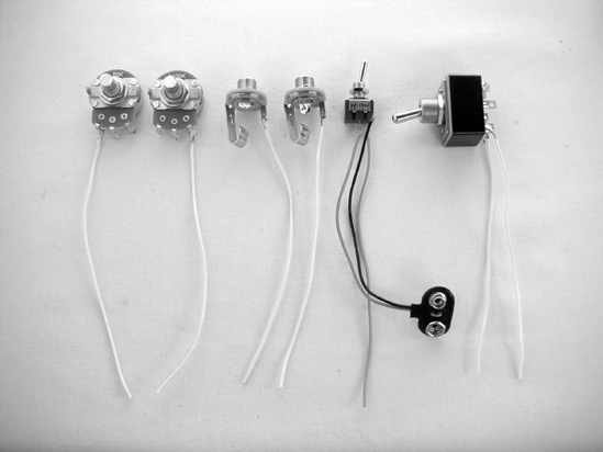
Put together the hardware shown in Figure 16-7. As in the last effect, wire the DPDT switch with a length of bare bus wire between lugs 1 and 6 and insulated wire going to lugs 2 and 4 (see Figure 15-5 in Building It for details). Cut five more lengths of insulated wire. Solder one wire to one lug of the small SPST switch, one wire to lug 3 of the 5k pot, and one wire to lug 1 of the 100k pot. Solder wires to the tips of each jack, and solder the red battery lead to the open lug of the SPST switch. Finally, solder a short length of bare bus wire between lugs 2 and 3 of the 5k pot. Label the 5k pot G (for gain) and the 100k pot V (for volume). (Check the appendix if you are confused by potentiometer and jack lugs.)
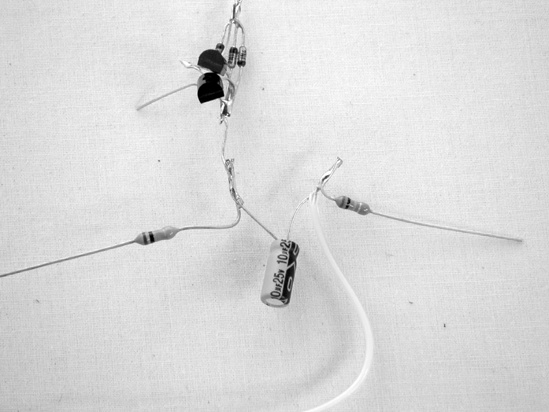
Twist together one leg of one 10k resistor (brown-black-orange), the positive (non-striped) leg of the 10 μF capacitor, and the collector on the transistor pair, and solder them. Then twist together the negative leg of the 10 μF capacitor, one leg of the other 10k resistor, and the wire connected to pot V, and solder all three together, as shown in Figure 16-8. The other leg of this second 10k resistor will be soldered to the common ground bus in Step 11, thus clamping the signal and helping weed out AM radio interference, which is a problem with this circuit, since it is essentially a high-gain amp with a bunch of diodes crammed into it. For more on AM radio, see Figure 12-13 and The One-Component AM Radio in Tweaking the Amp.
Solder the other leg of the first 10k resistor (that’s the resistor connected to the positive leg of the 10 μF capacitor) to the insulated wire attached to the lug of the small SPST switch.
Connect the insulated wire on pot G to the emitter of the transistor pair.
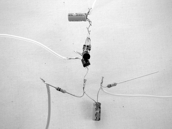
Connect the negative leg of the 1.5 μF capacitor to the base of the transistor pair. (This is the input to the fuzztone; if you want a muddier tone, replace this capacitor with a larger electrolytic capacitor, like a 22 μF; to get more treble, use a smaller cap, like a 0.22 μF.)
Connect the positive leg of the 1.5 μF capacitor to the wire that goes to lug 2 of the DPDT switch (Figure 16-9 shows the completed circuit). Now connect the input jack to lug 1 of the DPDT switch and the output jack to lug 5. Finally, connect the middle lug of pot V to lug 4 of the DPDT switch.
Run the ground bus: Use bare wire to connect both jacks’ ground lugs, the open lug on pot V, the open lug on pot G, the remaining leg of the 10k resistor attached to pot V, lug 3 of the DPDT switch, and the black lead of the battery clip.
Test it out: Spin pot G completely counterclockwise, set pot V to its midpoint, plug a “regular” guitar or the $10 Electric Guitar (Chapter 13) into the input jack and an amp into the output jack, connect a battery, and flick the power switch. Try both settings for the DPDT switch; when the DPDT is in one position, the instrument’s volume will be markedly quieter (because the volume—controlled by pot V—is only at half-mast); that’s the activated position. Leave the Fuzztone activated, and crank the volume knob (pot V) to full clockwise; the instrument should be about as loud as it would be with the effect deactivated. Start turning up the gain (pot G); the tone will first get subtly fuzzier and then much louder and more aggressively distorted. Use the volume knob to keep it at a tolerable loudness as you increase the gain; the overdriven distortion and increased sustain will remain, no matter how quiet you make the signal. As you play, you’ll find that this fuzztone is highly responsive to your playing dynamics; you’ll get more fuzz and bite if you pluck harder or use a pick.
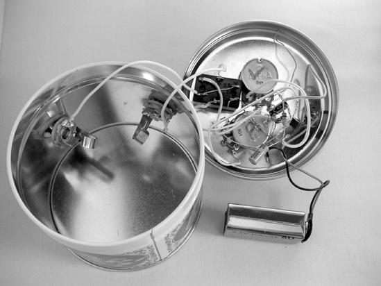
Cram it into a box à la Figure 16-10. It’s a good idea to shield this effect by using a conductive enclosure (like this candy tin) and connecting the enclosure to the ground bus. As before, a 1/4″ bit is good for drilling a hole for the power switch, while 1/2″ or 3/8″ bits are best for the DPDT switch, jacks, and potentiometers.