
We are now going to configure the hardware part of the project. As we have a relatively small number of simple components, the configuration of this project will be really easy and straightforward. This is a schematic to help you out:
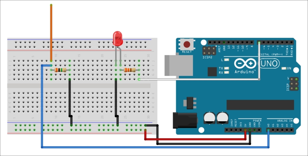
As you can see, the LCD screen is not present on this schematic. We'll first see how to connect all the other components and then see how to connect the LCD screen at the end of this section.
First, connect the power to the breadboard: connect GND to the blue power rail of the breadboard and the +5V pin to the red power rail.
Then, we are going to connect the antenna: first, place it on the breadboard in series with the 1M Ohm resistor. Then, connect the other end of the resistor to the ground. Finally, connect the antenna to the A0 analog pin.
For the LED, simply place it in series with the resistor, as seen on the schematic. Ensure that you connect the resistor to the anode of the LED, which is the longest pin of the LED. Finally, connect the other end of the resistor to the digital pin 7 and the other end of the LED to ground.
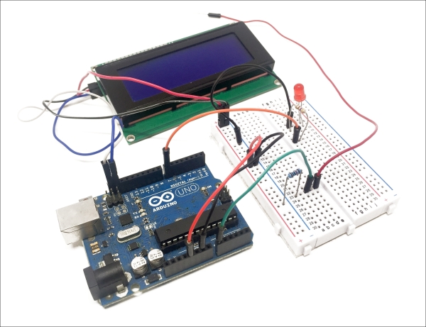
For the LCD screen, the connections are really easy, thanks to the I2C interface. First connect the power: VCC goes to the red power rail and GND to the blue power rail. For the data pin, connect SDA and SCL to their respective pins on the Arduino board, which are next to the digital pin 13.
The following image is the final result:
Congratulations! We are now going to see how to test the LCD screen.