
Now that we managed to actually control the relay and the LED by sending text messages to the FONA shield, we can connect the actual lock. This last step of the project is optional as you already tested the main functionality of the project and connecting the electronic door lock is a bit more technical. This is an image of the lock that I used:
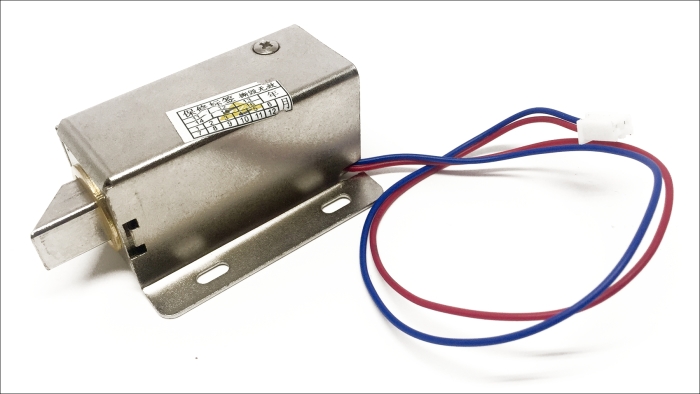
First, you'll need to cut the JST connector from the electronic lock in order to be able to connect it the breadboard. I soldered some 2-pin header at the end of the electronic lock to make it compatible with my breadboard.
Then, you'll need to assemble the remaining optional components on the breadboard, as shown in the following schematic:
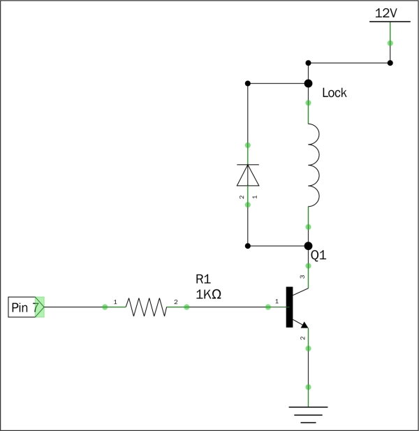
Let's see how to assemble these components together. First, place all the components on the breadboard. Then, connect the digital pin 7 of the Arduino board to the base of the transistor via the 1K Ohm resistor. Also, connect the emitter of the transistor to the ground of the project. Then, connect the electronic door lock between the collector of the transistor and the 12V power supply. Finally, mount the rectifier diode parallel to the door lock, with the orientation defined on the schematic.
Then, it's time to test the project again. You can use the exact same code as in the previous section. Congratulations, you can now control a door lock by sending a secret passphrase via SMS!