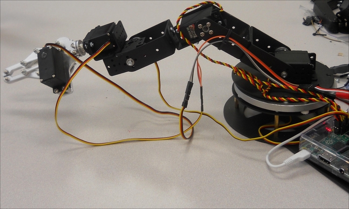
You can now ask your arm to hold a drawing pen by simply opening the claw, inserting a pen, and closing the claw. You'll probably want to use some sort of marker or other drawing device with a wide tip and lots of color. The following is the arm holding the pen:
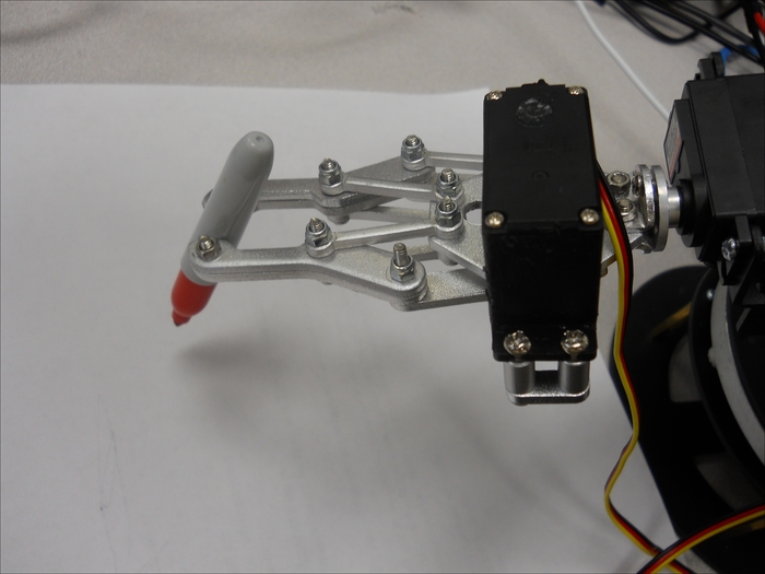
If you adjust the servo that moves the entire arm up and down, you can make the pen touch the paper, as follows:
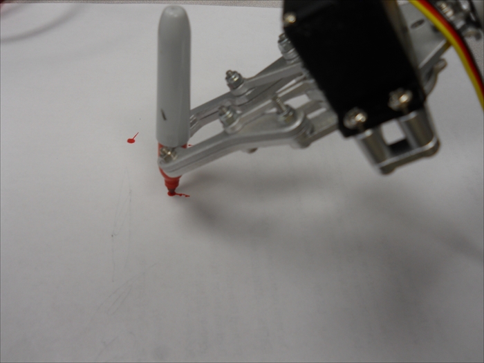
Finally, if you move the servo that turns the base, you can draw your first curved line, similar to the following image:
This is wonderful, but drawing only curved lines will not be particularly useful; besides, an interface where the user enters the servo locations one at a time to try and draw a more complex drawing will be unacceptable. What you need is a program that takes an x-y location input and moves the robotic arm to that point with the proper servo positions.
Since the input coming from the computer will be the x and y location for a point, you'll need to translate that value into the proper angle positions for your arm. This can be done in two ways; first, you can build a translation lookup table for the servo locations for each x and y location on the paper and second, you can model the positions of the servo using mathematical formulas to determine the servo locations.
If you want to build a translation table, one key question is how many individual x and y locations you'll want to define for your robotic arm. With more points, the table will be larger, but you'll also be able to draw a finer resolution. It is best to start with a table that isn't particularly fine, for example, 60 in the y axis and 40 in the x axis. This gives you 2,400 individual locations to store the values of the four servos. You'll not need to store the values for servos 4 and 5, they won't vary much for each implementation. You can simply walk through each location and note the value of the servos, store these in a table, and then retrieve the proper servo location for each position. You'll also want a similar table to hold the values when you want your robot arm to raise the pen from the paper.
Perhaps a better approach, or at least one that won't take as much time to calibrate, is to build a mathematical model for the position of each of the servos for the x and y locations on the paper. The following is a view, looking down on the paper, of the four corners as marked by the robotic arm:
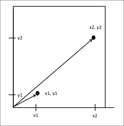
If you think of the arm being placed in the lower left corner, you can use mathematics to build a model of how to turn the angle of the position of the servo at the base of the arm to position it for two different points, as shown in the following diagram:
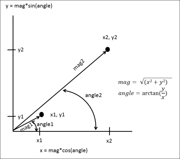
These equations show the relationship among the point x, point y, angle, and distance to the point. The angle calculation here can be used to position the servo at the base of the arm, servo 0. Adjusting the magnitude is a bit more difficult, you'll be using servo 2 to adjust the distance of the arm to the point. This calculation will look something similar to the following diagram:
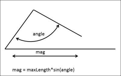
In this case, maxLength is the length of the arm when the angle of servo 2, at the elbow joint of the arm, is 90 degrees. Now there is actually the opportunity to go further but making this the max length will keep your calculations simple. The final calculation will be the calculation of the angle of servo 1, which can then raise the entire arm up and down. This servo will need to be set such that, based on the length of the arm, the servo will need to be raised or lowered to set this value. This value will also be set using a cos/sin equation, but based on the cos/sin of the angle of servo 2.
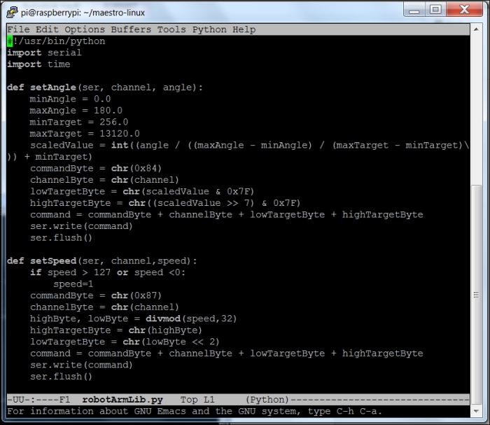
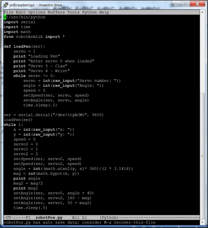
To code this, start by putting the setAngle() and setSpeed() functions into a library program, as shown in the following screenshot:
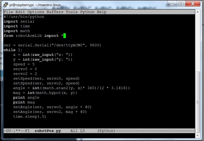
Now, you'll create a simple program that can position the base servo using the x and y locations, as shown in the following screenshot:
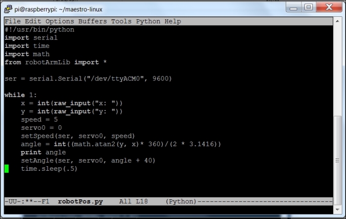
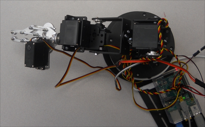
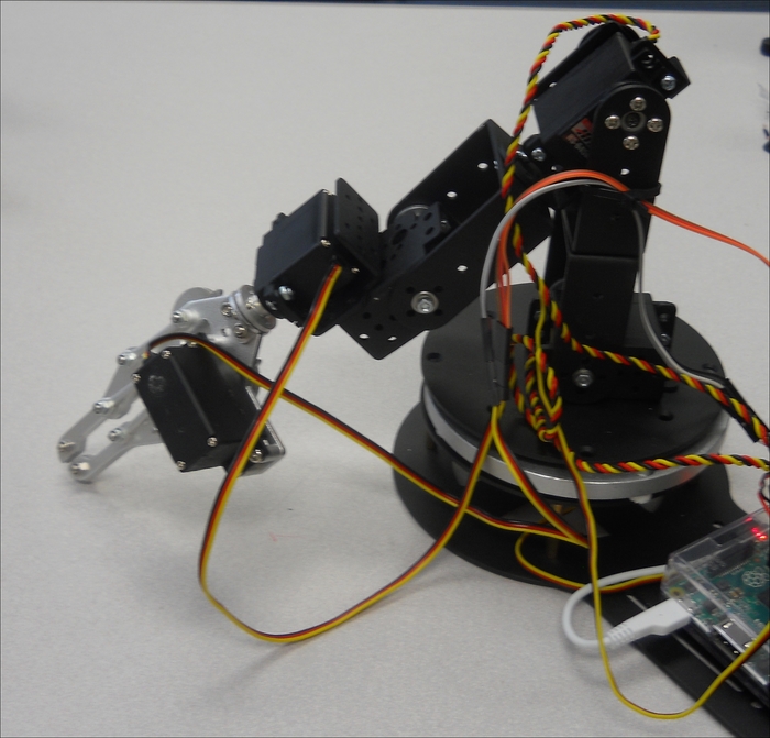
You'll use the robotArmLib library and its setSpeed() and setAngle() functions to set the position of the arm. Notice that this is all based on the x = 0 and y = 0 locations being at the center of the arm. On entering x = 50 and y = 0, the arm will position itself as shown in the following image:
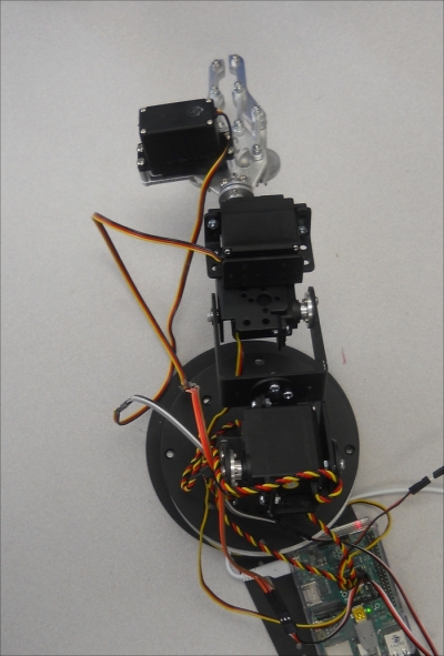
If you enter x = 0 and y = 50, you will see the arm in the following position:
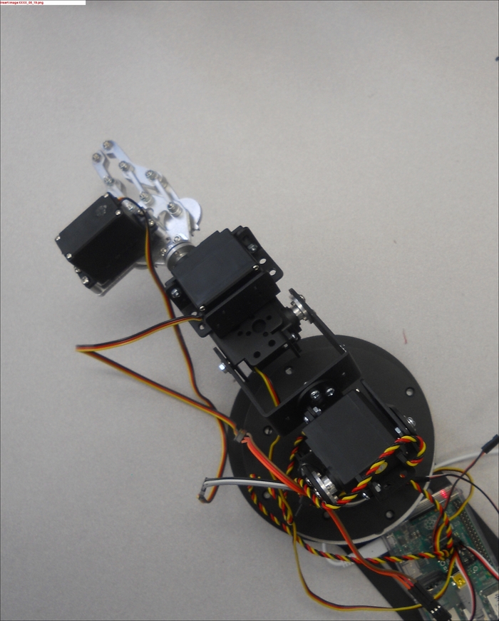
And finally, setting x = 50 and y = 50 will move the arm to the following position:
Now that you can position the base angle correctly, you'll need to position servo 2, at the elbow joint, to move in and out based on the distance from the center of the base. This code adds the control by adjusting servo 2 based on the magnitude of the distance:
So, for x = 10 and y = 0, the arm would be positioned as shown in the following image:
And, for x = 100 and y = 0, the arm would be positioned as follows:

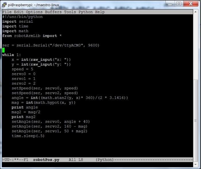
Now, you will need to change the servo setting for servo 1, at the base of the arm, to move the position so that the pen is on the paper. This angle will be controlled in a similar fashion to servo 2. Here is the entire code:
Using this code and asking for x = 10 and y = 0 now gives the total arm position as follows:
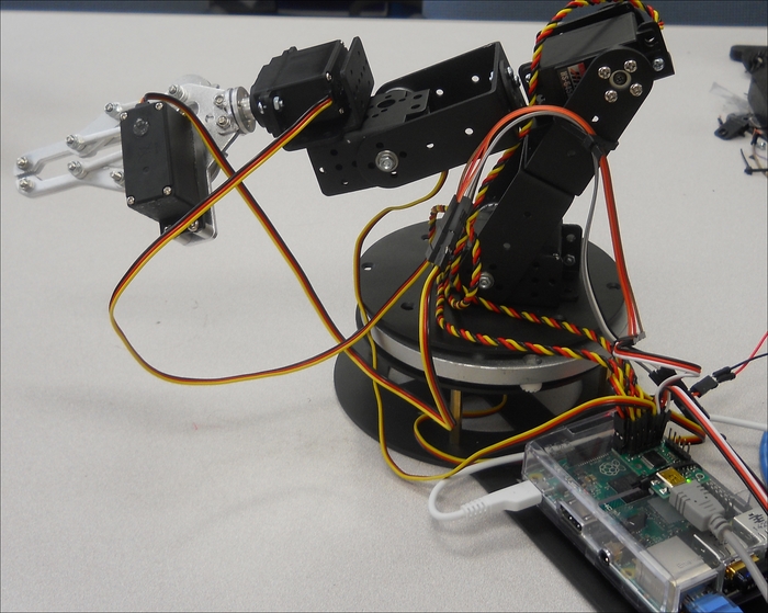
And, for x = 100 and y = 0, the total arm position is shown in the following image:
Now you can position the pen for each individual x and y location. You will, however, notice that the entire space between 100 and 10 is not linear and, as you get closer to the arm, it is more difficult to keep the pen on the paper. You should evaluate the available drawing distance, it may be between 100 and 50. The best way to evaluate this is to place a pen in the robot's hand and simply begin to draw the points in order to understand the boundaries of the robot's workable range.
This final Python code adds a loading function in order to load the pen and position it in the robot's claw:
The next step is to add an application that will control the program more elegantly than simply typing in the x and y locations.