
For many years, people physically interacted with electrical appliances using hardware switches. Now that things have changed, thanks to the advances in technology and hardware, controlling a switch over the Internet without any form of physical interaction has become possible.
In this chapter, we will incrementally build a web server-enabled smart power switch that can be controlled through the Internet with a wired Internet connection. Let's move to Arduino's IoT (Internet of Things).
In this chapter, you will do the following:
- Learn about Arduino UNO and Arduino Ethernet Shield basics
- Learn how to connect a PowerSwitch Tail with Arduino UNO
- Build a simple web server to handle client requests and control the PowerSwitch accordingly
- Build a simple mains electricity (general purpose alternating current) sensor with 5V DC wall power supply
- Develop a user friendly UI (User Interface) with HTML (Hyper Text Markup Language) and Metro UI CSS (Cascade Style Sheet)
This project consists of a DC (Direct Current) activated relay switch with an embedded web server that can be controlled and monitored through the Internet and the integrated mains electricity sensor that can be used to get the status of the availability of mains electricity. The possible applications are:
- Controlling electrical devices such as lamp posts, water pumps, gates, doors, and so on, in remote locations
- Sensing the availability of mains electricity in houses, offices, and factories remotely
- Detecting whether a door, window, or gate is open or shut
All the hardware and software requirements are mentioned within each experiment. Most of the hardware used in this project are open source, which allows you to freely learn and hack them to make more creative projects based on the blueprints of this chapter.
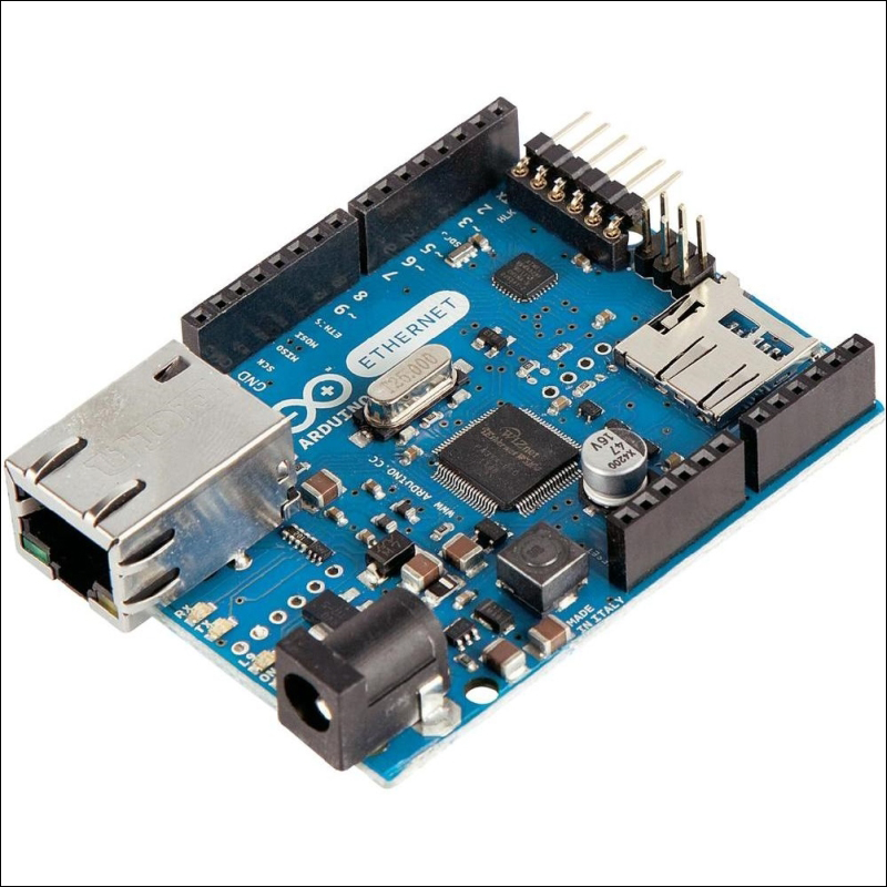
Arduino Ethernet Shield is used to connect your Arduino UNO board to the Internet. It is an open source piece of hardware and is exactly the same size as the Arduino UNO board. The latest version of the Arduino Ethernet Shield is R3 (Revision 3). The official Arduino Ethernet Shield is currently manufactured in Italy and can be ordered through the official Arduino website (https://store.arduino.cc). Also, there are many Arduino Ethernet Shield clones manufactured around the world that may be cheaper than the official Arduino Ethernet Shield. This project is fully tested with a clone of Arduino Ethernet Shield manufactured in China.
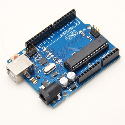
Arduino UNO R3 (Front View)
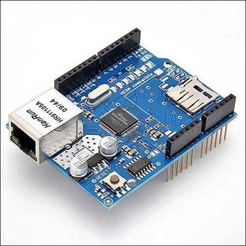
Arduino Ethernet Shield R3 (Front View)
Plug your Arduino Ethernet Shield into your Arduino UNO board using wire wrap headers so that it's exactly intact with the pin layout of the Arduino UNO board. The following image shows a stacked Arduino UNO and Arduino Ethernet Shield together:
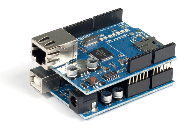
Arduino Ethernet Shield R3 (top) is stacked with Arduino UNO R3 (bottom) (Front View)
Arduino Ethernet Shield consists of an Ethernet controller chip—WIZnet W5100—the only proprietary hardware used with the shield. The WIZnet W5100 includes a fully hardwired TCP/IP stack, integrated Ethernet MAC (Media Access Control), and PHY (Physical Layer).
The hardwired TCP/IP stack supports the following protocols:
The WIZnet W5100 Ethernet controller chip also simplifies the Internet connectivity without using an operating system.
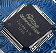
The WIZnet W5100 Ethernet controller (Top View)
Throughout this chapter, we will only work with TCP and IPv4 protocols.
The Arduino UNO board communicates with the Arduino Ethernet Shield using digital pins 10, 11, 12, and 13. Therefore, we will not use these pins in our projects to make any external connections. Also, digital pin 4 is used to select the SD card that is installed on the Arduino Ethernet Shield, and digital pin 10 is used to select the Ethernet controller chip. This is called SS (Slave Select) because the Arduino Ethernet Shield is acting as the slave and the Arduino UNO board is acting as the master.
However, if you want to disable the SD card and use digital pin 4, or disable the Ethernet controller chip and use digital pin 10 with your projects, use the following code snippets inside the setup() function:
- To disable the SD card:
pinMode(4,OUTPUT);
digitalWrite(4, HIGH);
- To disable the Ethernet Controller chip:
pinMode(10,OUTPUT);
digitalWrite(10, HIGH);
The Arduino Ethernet board is a new version of the Arduino development board with the WIZnet Ethernet controller built into the same board. The USB to serial driver is removed from the board to keep the board size the same as Arduino UNO and so that it can be stacked with any Arduino UNO compatible shields on it.
You need an FTDI cable compatible with 5V to connect and program your Arduino Ethernet board with a computer.
The Arduino Ethernet board (Front View)
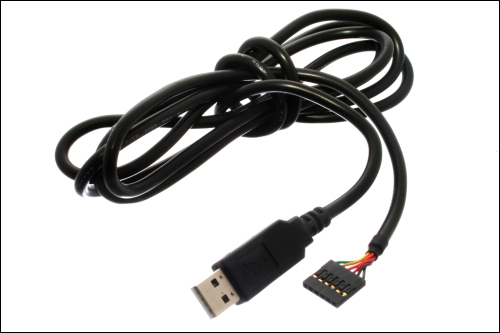
FTDI cable 5V (Source: https://commons.wikimedia.org/wiki/File:FTDI_Cable.jpg)
You can visit the following links to get more information about the Arduino Ethernet board and FTDI cable:
- The Arduino Ethernet board (https://store.arduino.cc/product/A000068)
- FTDI cable (https://www.sparkfun.com/products/9717)
You can build all the projects that are explained within this chapter and other chapters throughout the book with the Arduino Ethernet board using the same pin layout.
To connect your Ethernet shield to the Internet, you require the following hardware:
- An Arduino UNO R3 board (https://store.arduino.cc/product/A000066)
- A 9VDC 650mA wall adapter power supply. The barrel connector of the power supply should be center positive 5.5 x 2.1 mm. (Here is the link for a perfect fit: https://www.sparkfun.com/products/298)
- A USB A-to-B male/male-type cable. These types of cables are usually used for printers (https://www.sparkfun.com/products/512)
- A Category 6 Ethernet cable (https://www.sparkfun.com/products/8915)
- A router or switch with an Internet connection
Use the following steps to make connections between each hardware component:
- Plug your Ethernet shield into your Arduino board using soldered wire wrap headers:
Fritzing representation of Arduino and Ethernet shield stack
- Get the Ethernet cable and connect one end to the Ethernet jack of the Arduino Ethernet Shield.
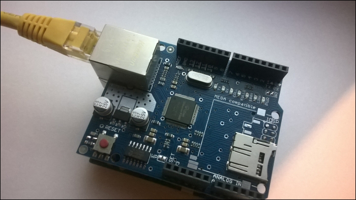
One end of the Ethernet cable is connected to the Arduino Ethernet board
- Connect the other end of the Ethernet cable to the Ethernet jack of the network router or switch.
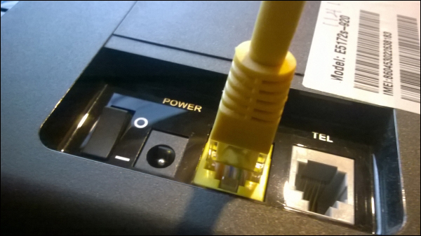
The other end of the Ethernet cable is connected to the router/switch
- Connect the 9VDC wall adapter power supply to the DC barrel connector of the Arduino board.
- Use the USB A-to-B cable to connect your Arduino board to the computer. Connect the type A plug end to the computer and the type B plug end to the Arduino board.
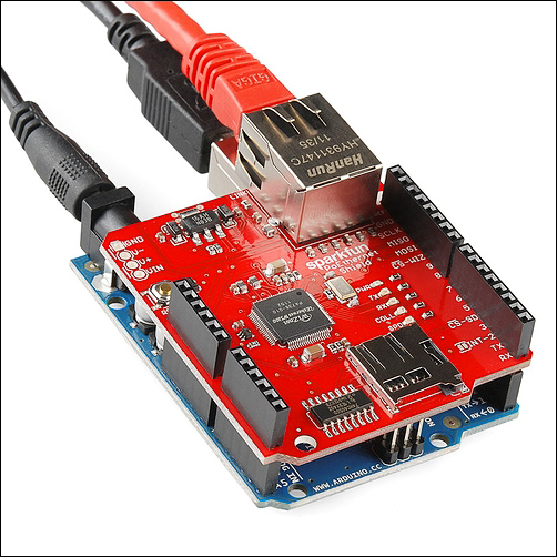
One end of the Ethernet cable is connected to the Ethernet shield (top) and the power connector and USB cable are connected to the Arduino board (bottom) Image courtesy of SparkFun Electronics (https://www.sparkfun.com)
To test you Arduino Ethernet Shield, follow these steps:
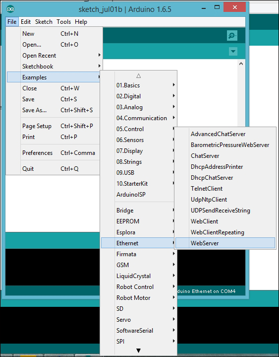
- Open your Arduino IDE and navigate to File | Examples | Ethernet | WebServer:
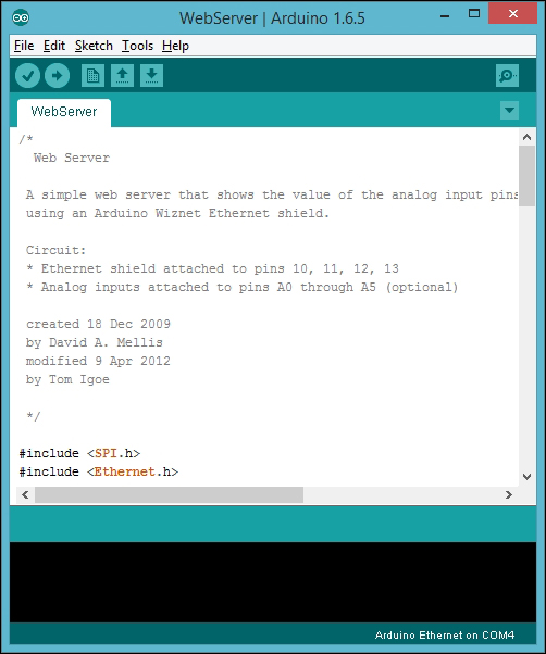
- The sample sketch WebServer will open in a new Arduino IDE:
- You can also paste the code from the sketch named
B04844_01_01.inofrom the code folder of this chapter. The following header files should be included for serial communication and Ethernet communication in the beginning of the sketch:#include <SPI.h> //initiates Serial Peripheral Interface #include <Ethernet.h> //initiates Arduino Ethernet library
- Replace the MAC address with your Ethernet shield's MAC address if you know it. You can find the printed sticker of the MAC address affixed to the back of your Ethernet shield. (Some clones of Arduino Ethernet Shield don't ship with a MAC address affixed on them). If you don't know the MAC address of your Arduino Ethernet Shield, use the one mentioned in the sample code or replace it with a random one. But don't use network devices with the same MAC address on your network; it will cause conflicts and your Ethernet shield will not function correctly. (Read Finding the MAC address and obtaining a valid IP address for more information on MAC addresses).
byte mac[] = {0xDE, 0xAD, 0xBE, 0xEF, 0xFE, 0xED}; - Replace the IP address with a static IP in your local network IP range. (Read the Finding the MAC address and obtaining a valid IP address section for selecting a valid IP address).
IPAddress ip(192, 168, 1, 177);
- Then, create an instance of the Arduino Ethernet Server library and assign port number 80 to listen to incoming HTTP requests.
EthernetServer server(80);
- Inside the
setup()function, open the serial communications and wait for the port to open. The computer will communicate with Arduino at a speed of 9600 bps.Serial.begin(9600);
- The following code block will start the Ethernet connection by using the MAC address and IP address (we have assigned a static IP address) of the Arduino Ethernet Shield and start the server. Then it will print the IP address of the server on Arduino Serial Monitor using
Ethernet.localIP():Ethernet.begin(mac, ip); server.begin(); Serial.print("server is at "); Serial.println(Ethernet.localIP()); - Inside the
loop()function, the server will listen for incoming clients.EthernetClient client = server.available();
- If a client is available, the server will connect with the client and read the incoming HTTP request. Then, reply to the client by the standard HTTP response header. The output can be added to the response header using the
EthernetClientclass'sprintln()method:if (client) { Serial.println("new client"); // an http request ends with a blank line boolean currentLineIsBlank = true; while (client.connected()) { if (client.available()) { char c = client.read(); Serial.write(c); // if you've gotten to the end of the line (received a newline // character) and the line is blank, the http request has ended, // so you can send a reply if (c == ' ' && currentLineIsBlank) { // send a standard http response header client.println("HTTP/1.1 200 OK"); client.println("Content-Type: text/html"); client.println("Connection: close"); // the connection will be closed after completion of the response client.println("Refresh: 5"); // refresh the page automatically every 5 sec client.println(); client.println("<!DOCTYPE HTML>"); client.println("<html>"); // output the value of each analog input pin for (int analogChannel = 0; analogChannel < 6; analogChannel++) { int sensorReading = analogRead(analogChannel); client.print("analog input "); client.print(analogChannel); client.print(" is "); client.print(sensorReading); client.println("<br />"); } client.println("</html>"); break; } if (c == ' ') { // you're starting a new line currentLineIsBlank = true; } else if (c != ' ') { // you've gotten a character on the current line currentLineIsBlank = false; } } } // give the web browser time to receive the data delay(1); - Finally, close the connection from the client using the
EthernetClientclass'sstop()method:client.stop(); Serial.println("client disconnected"); - Verify the sketch by clicking on the Verify button located in the toolbar.
- On the menu bar, select the board by navigating to Tools | Board | Arduino UNO. If you are using an Arduino Ethernet board, select Tools | Board | Arduino Ethernet.
- On the menu bar, select the COM port by navigating to Tools | Port and then selecting the port number.
- Upload the sketch into your Arduino UNO board by clicking on the Upload button located in the toolbar.
- Open your Internet browser (such as Google Chrome, Mozilla Firefox, or Microsoft Internet Explorer) and type the IP address (
http://192.168.1.177/) assigned to your Arduino Ethernet Shield in the sketch (in Step 4), and hit the Enter key. - The web browser will display analog input values (impedance) of all the six analog input pins (A0-A5). The browser will refresh every 5 seconds with the new values. Use following code to change the automatic refresh time in seconds:
client.println("Refresh: 5");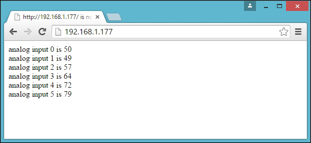
Output for Arduino Ethernet board: Analog input values are displaying on the Google Chrome browser, refreshing every 5 seconds
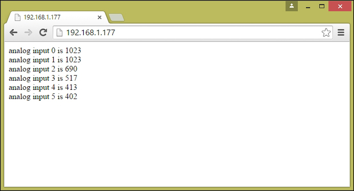
Output for Arduino UNO + Arduino Ethernet Shield: Analog input values are displaying on the Google Chrome browser, refreshing every 5 seconds

Arduino Serial Monitor prints the static IP address of Arduino Ethernet Shield
- To make your sketch more stable and to ensure that it does not hang, you can do one of the following:
Now you can be assured that your Arduino Ethernet Shield is working properly and can be accessed through the Internet.