
The heart of the TTL Serial Camera module (the product page at Adafruit named it as TTL Serial JPEG Camera) is the VIMICRO VC0706 Digital video Processor. The following are some of the features that a VC0706 digital video processor has:
- CMOS sensor interface and digital video input interface, so it can capture video using the CMOS sensor or external TV decoder
- Embedded TV encoder and video DAC, so it can directly output NTSC/PAL video streams to TV monitors and other 75 ohm display devices
- Preimage processing and M-JPEG compression ability
- NTSC video output resolution up to 712 x 486
- PAL video output resolution up to 704 x 576
- Maximum frame rate; 60fps @ 27MHz in NTSC and 50fps @ 27MHz in PAL
- Ability to change the brightness, saturation, and hue of images
- Auto brightness and auto contrast adjustment
- Motion detection
The VC0706 chipset specification mentioned that it supports both NTSC and PAL but the TTL Serial Camera module only implemented NTSC.
The TTL Serial Camera is only just a breakout board and has no wires, so you need to solder wires into the connection pads. It has five connection pads, which are 2mm apart from each other.
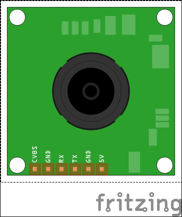
A Fritzing representation of TTL Serial Camera—top view
The pin labels and their core operation is listed as follows:
You need four wires if you are only planning to capture color images with a TTL serial camera.
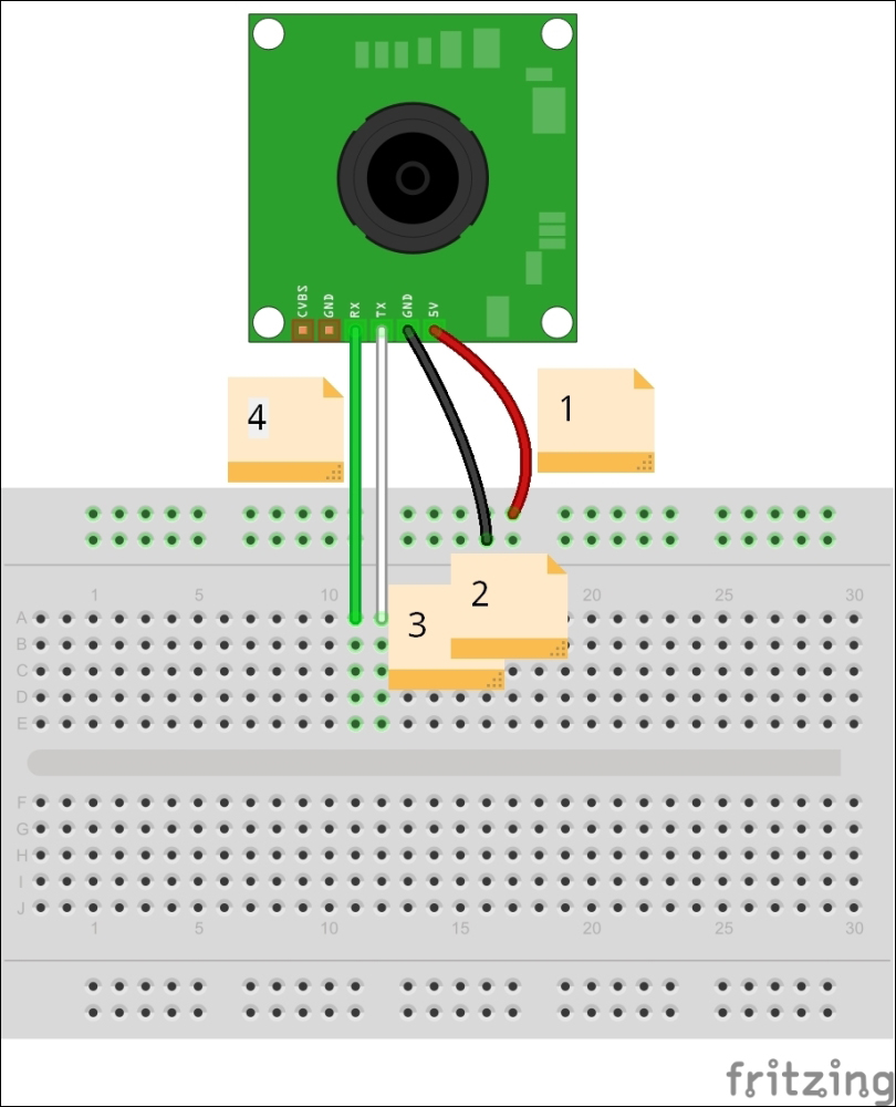
Wiring for image capturing in the JPEG format
Solder wires to the connection pads are mentioned as:
The TTL Serial Camera board only supports NTSC video output and cannot be used as PAL. Now, solder two additional wires as shown in the following diagram:
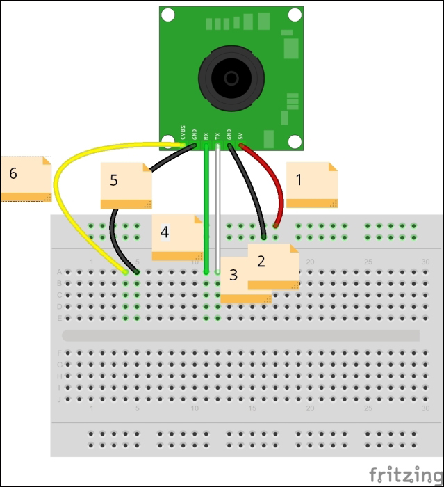
Wiring for video capturing with NTSC monochrome
Solder additional wires to the connection pads are mentioned as:
Use an RCA jack and solder two wires, as stated here:
- Solder a yellow wire to the center terminal
- Solder a black wire to the outer terminal
Then make the other connections as follows:
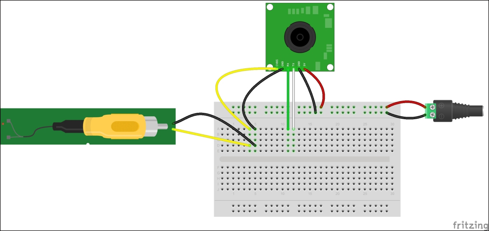
- Connect the yellow wire to the RCA jack's signal terminal.
- Connect the black wire to the RCA jack's ground terminal.
- Now, connect the TTL serial camera to a regulated 5V power source, the red wire to positive, and the black wire to negative. You can use an Arduino board to get the regulated 5V power. Connect the red wire to Arduino 5V pin and the black wire to Arduino GND pin, and connect Arduino to the 9v power supply.
- Finally, connect the soldered RCA jack to the NTSC monitor using an RCA video cable. If you are living in a region that does not support the NTSC broadcasting system, then you have to purchase a basic NTSC/PAL monitor. But some televisions support both NTSC and PAL broadcasting systems. Check your television's user manual for more information. If it does not support NTSC, then you have to purchase an NTSC- supported monitor from Adafruit (http://www.adafruit.com/product/946), or search eBay for a cheaper one.
Now, power up the monitor. You can see the monochrome video that has been captured by the TTL Serial Camera module. Next, we will move on to the most difficult part.