
The following Fritzing schematic representation shows you how to wire each component together with the Arduino board to build the IR Receiver module. It shows the connection between each electronic component:
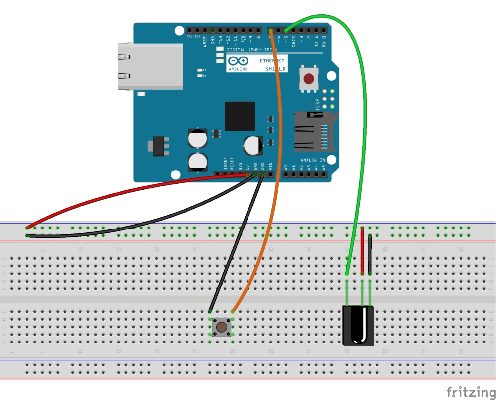
The IR receiver: The TSOP382 IR receiver is attached to the Arduino+ Ethernet Shield - Fritzing representation
- Use the stack Arduino Ethernet Shield with the Arduino UNO board using wire wrap headers, or the Arduino Ethernet board instead.
- The TSOP382 IR receiver diode has three pins, as shown in the following image:
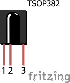
The TSOP382 IR receiver diode from Vishay (http://www.vishay.com/)
These three pins are:
- OUT: Signal
- GND: Ground
- Vs: Supply voltage
- Connect the GND pin to Arduino Ground (GND), and then connect the Vs pin to Arduino 5V. Finally, connect the OUT pin to the Arduino digital pin 5.
- Connect the mini push button switch between the Arduino ground (GND) and the Arduino digital pin 7.
You can capture the IR commands sent from the remote control in a hexadecimal notation:
- Open a new Arduino IDE and paste the code,
B04844_08_01.ino, from theChapter 8code folder. Alternately, you can open the same file from File | Examples | IRremote | IRrecvDemo. - We have included the header file,
IRremote.h, at the beginning of the sketch:#include <IRremote.h>
- Next, declare a digital pin to receive IR commands. This is the data pin of the TSOP382 IR receiver diode that is connected with the Arduino. Change the pin number according to your hardware setup:
int RECV_PIN = 5;
- Create an object,
irrecv, using theIRrecvclass, and use theRECV_PINvariable that was declared in the preceding line as the parameter:IRrecv irrecv(RECV_PIN);
- Finally, declare variable
resultshas a type ofdecode_results:decode_results results;
- Inside the
setup()function, start the serial communication with 9,600 bps and start the IR receiver using theenableIRIn()function:void setup() { Serial.begin(9600); irrecv.enableIRIn(); // Start the receiver } - Inside the
loop()function, we continuously check any incoming IR commands (signals) and then decode and print them on the Arduino Serial Monitor as hexadecimal values:void loop() { if (irrecv.decode(&results)) { Serial.println(results.value, HEX); irrecv.resume(); // Receive the next value } delay(100); } - Verify and upload the sketch on your Arduino board or Arduino Ethernet board. If you get compiler errors as follows, it is definitely because of the confliction of two or more IRremote libraries. To resolve this, navigate to the Arduino libraries folder and delete the
RobotIRremotefolder, or rename the folder,Arduino-IRremote-master, toIRremote. Now, close and open the Arduino IDE with the sketch file and try to verify the sketch again. This will fix the compiler error: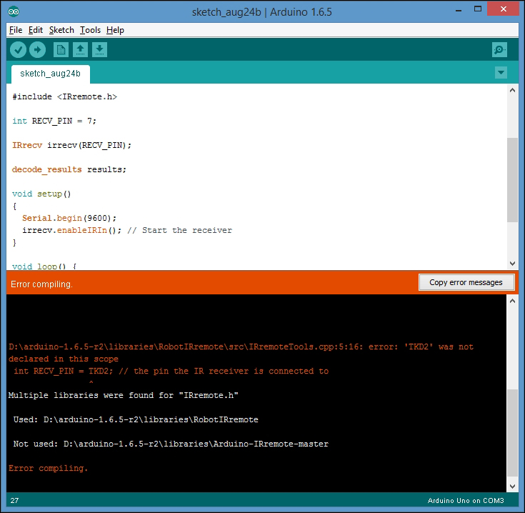
The compiler error because of the conflicting libraries
- Once uploaded, open the Arduino Serial Monitor.
- Get your TV remote control and point it toward the TSOP382 IR sensor. Press any key on your TV remote control. You will see a hexadecimal number displayed on the serial monitor for each key press. Each key on your TV remote has a unique hexadecimal value. The values you captured here will be required in the next step of our project.
For testing purposes, we used a Samsung television (model number: UA24H4100) remote control to capture IR command values for the volume up and volume down buttons. the following image shows the captured output:
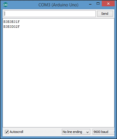
Hexadecimal values for SAMSUNG UA24H4100 TV volume up and volume down remote control buttons
The command values for volume up and volume down in a hexadecimal format are as follows:
VOLUME UP: E0E0E01F
VOLUME DOWN: E0E0D02F
Capturing IR commands in the raw format is very useful when you send them back to the target device later. The following steps will guide you in capturing the IR commands sent by a remote control in the raw format:
- Open a new Arduino IDE and paste the sketch,
B04844_08_02.ino, from theChapter 8sample code folder. Alternately, you can open the sketch by clicking on File | Examples | IRremote | IRrecvDumpV2. - Change the pin number of the following line if you have attached the IR receiver diode to a different Arduino pin:
int recvPin = 5;
- Verify and upload the sketch on your Arduino board, and then, open the Arduino Serial Monitor.
- Point your remote control to the IR receiver diode and press the volume up button, and then the volume down button. You will see outputs on the Arduino Serial Monitor similar to the following:
Encoding  : SAMSUNG
Code      : E0E0E01F (32 bits)
Timing[68]:
     -47536
     +4700, -4250     + 750, -1500     + 700, -1500     + 700, -1550
     + 700, - 400     + 700, - 400     + 700, - 400     + 700, - 450
     + 650, - 450     + 650, -1600     + 600, -1600     + 650, -1600
     + 600, - 500     + 600, - 500     + 600, - 550     + 600, - 500
     + 600, - 500     + 600, -1650     + 550, -1650     + 600, -1650
     + 550, - 550     + 550, - 600     + 500, - 600     + 500, - 600
     + 550, - 550     + 550, - 600     + 500, - 600     + 500, - 600
     + 500, -1750     + 500, -1700     + 500, -1750     + 500, -1700
     + 500, -1750     + 500,
unsigned int  rawData[69] = {47536, 4700,4250, 750,1500, 700,1500, 700,1550, 700,400, 700,400, 700,400, 700,450, 650,450, 650,1600, 600,1600, 650,1600, 600,500, 600,500, 600,550, 600,500, 600,500, 600,1650, 550,1650, 600,1650, 550,550, 550,600, 500,600, 500,600, 550,550, 550,600, 500,600, 500,600, 500,1750, 500,1700, 500,1750, 500,1700, 500,1750, 500,0};  // SAMSUNG E0E0E01F
unsigned int  data = 0xE0E0E01F;

Encoding  : SAMSUNG
Code      : E0E0D02F (32 bits)
Timing[68]:
     -29834
     +4650, -4300     + 700, -1550     + 700, -1500     + 700, -1500
     + 700, - 450     + 700, - 400     + 650, - 500     + 600, - 500
     + 600, - 500     + 600, -1650     + 600, -1600     + 600, -1650
     + 600, - 500     + 600, - 500     + 600, - 550     + 550, - 550
     + 550, - 550     + 550, -1700     + 500, -1700     + 550, - 600
     + 500, -1700     + 550, - 550     + 550, - 600     + 500, - 600
     + 500, - 600     + 550, - 550     + 550, - 600     + 500, -1700
     + 550, - 550     + 550, -1700     + 500, -1700     + 550, -1700
     + 500, -1700     + 550,
unsigned int  rawData[69] = {29834, 4650,4300, 700,1550, 700,1500, 700,1500, 700,450, 700,400, 650,500, 600,500, 600,500, 600,1650, 600,1600, 600,1650, 600,500, 600,500, 600,550, 550,550, 550,550, 550,1700, 500,1700, 550,600, 500,1700, 550,550, 550,600, 500,600, 500,600, 550,550, 550,600, 500,1700, 550,550, 550,1700, 500,1700, 550,1700, 500,1700, 550,0};  // SAMSUNG E0E0D02F
unsigned int  data = 0xE0E0D02F;
Raw data for the Samsung UA24H4100 TV's volume up and volume down IR remote control buttons, Arduino Serial Monitor output text extract.
- Open a new Notepad file and paste the output to it because we will need some part of this output in the next section.
You can send any hardcoded IR command in the raw format using an Arduino sketch. In the previous section, we captured the IR raw data for the volume up and volume down buttons. In this example, we will learn how to send the hard coded IR command for volume up to the television. First, we have to build a simple IR sender module by adding an Infrared LED light and a 330 Ohm resistor.
The following Fritzing schematic shows how to wire each component together with the Arduino to build the IR Receiver module. It also shows the connection between each electronic component.
The following are additional wiring instructions for the circuit that you have previously built to capture the IR commands:
- Connect the infrared LED cathode (-) to the Arduino ground.
- Connect the infrared LED anode (+) to the Arduino digital pin 6 through a 330 Ohm resistor:
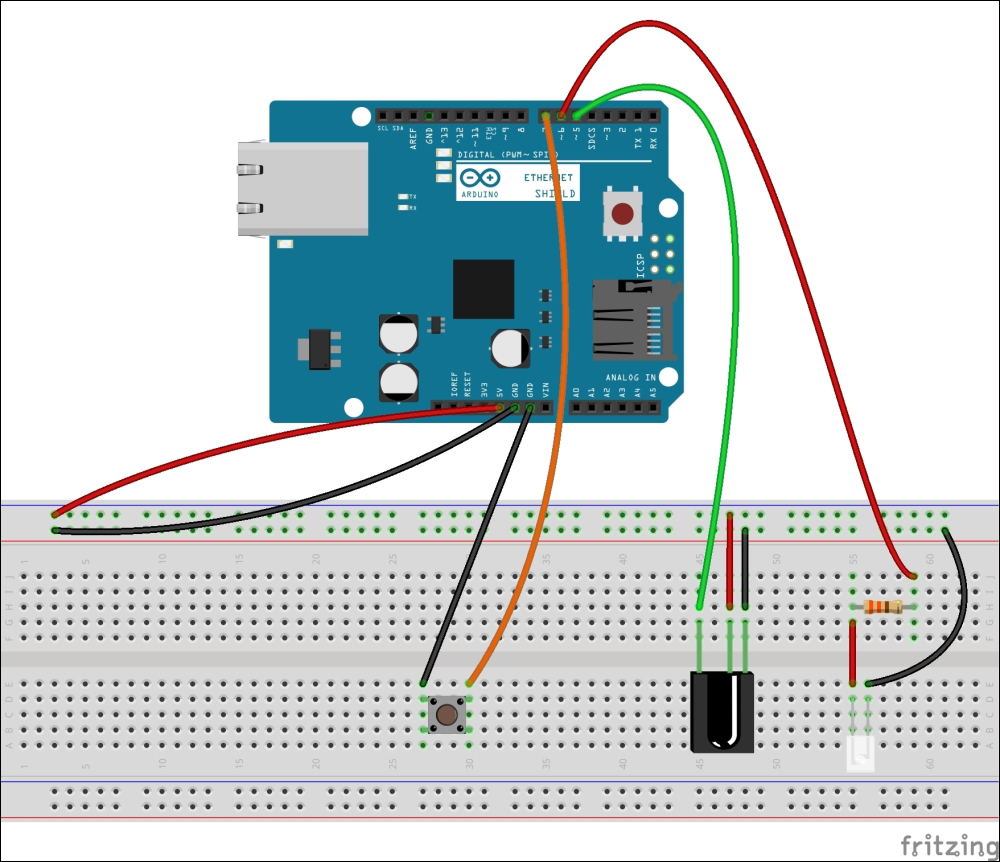
The IR sender: the infrared LED is attached to the Arduino Ethernet Shield—Fritzing representation
- Now, open a new Arduino IDE and copy the sample Arduino sketch,
B04844_08_03.ino, located in theChapter 8code folder. Verify and upload the sketch on your Arduino board. - To send the IR command for the volume up button, we need to identify the raw data array for the volume up command:
Encoding  : SAMSUNG
Code      : E0E0E01F (32 bits)
Timing[68]:
     -47536
     +4700, -4250     + 750, -1500     + 700, -1500     + 700, -1550
     + 700, - 400     + 700, - 400     + 700, - 400     + 700, - 450
     + 650, - 450     + 650, -1600     + 600, -1600     + 650, -1600
     + 600, - 500     + 600, - 500     + 600, - 550     + 600, - 500
     + 600, - 500     + 600, -1650     + 550, -1650     + 600, -1650
     + 550, - 550     + 550, - 600     + 500, - 600     + 500, - 600
     + 550, - 550     + 550, - 600     + 500, - 600     + 500, - 600
     + 500, -1750     + 500, -1700     + 500, -1750     + 500, -1700
     + 500, -1750     + 500,
unsigned int  rawData[69] = {47536, 4700,4250, 750,1500, 700,1500, 700,1550, 700,400, 700,400, 700,400, 700,450, 650,450, 650,1600, 600,1600, 650,1600, 600,500, 600,500, 600,550, 600,500, 600,500, 600,1650, 550,1650, 600,1650, 550,550, 550,600, 500,600, 500,600, 550,550, 550,600, 500,600, 500,600, 500,1750, 500,1700, 500,1750, 500,1700, 500,1750, 500,0};  // SAMSUNG E0E0E01F
unsigned int  data = 0xE0E0E01F;
The highlighted unsigned int array consists of 69 values separated by commas, and it can be used to increase the Samsung television's volume by 1. The array size differs depending on the device and remote control manufacturer.
Also, you need to know the size of the command in bytes. For this, it is 32 bits:
Code : E0E0E01F (32 bits)
The command will be sent to the target device when you press the mini push button attached to the Arduino. We have used the sendRaw() function to send the raw IR data:
for (int i = 0; i < 3; i++) {
    irsend.sendRaw(rawData,69,32)
    delay(40);
  }
The following is the parameter description for the sendRaw() function:
irsend.sendRaw(name_of_the_raw_array, size_of_the_raw_array, command_size_in_bits);
In Chapter 1, Internet-Controlled PowerSwitch, we learned how to control a PowerSwitch Tail through the internet by sending a command to the server using the GET method. The same mechanism can be applied here to communicate with the Arduino IR remote and activate the IR LED. To do this, perform the following steps:
- Open a new Arduino IDE and copy the sample code,
B04844_08_04.ino, into theChapter 8code folder. - Change the IP address and MAC address of the Arduino Ethernet Shield according to your network setup.
- Connect the Ethernet shield to the router, or switch via a Cat 6 Ethernet cable.
- Verify and upload the code on the Arduino board.
- Point the IR LED to the Television.
- Open a new web browser (or new tab), type the IP address of the Arduino Ethernet Shield,
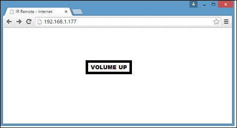
http://192.168.1.177/and then hit Enter. If you want to control the device through the Internet, you should set up port forwarding on your router. - You will see the following web page with a simple button named VOLUME UP:
- Now, click on the button. The volume of the television will increase by 1 unit. Click on the VOLUME UP button several times to increase the volume. Also, note that the address bar of the browser is similar to
http://192.168.1.177/?volume=up: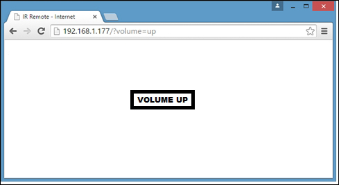
Likewise, you can add the VOLUME DOWN function to the Arduino sketch and control the volume of your television. Apply this to an air conditioner and try to control the power and temperature through the Internet.