Haptic feedback is the way to convey information to users using advanced vibration patterns and waveforms. Earlier consumer electronic devices communicated with their users using audible and visual alerts, but now things have been replaced with vibrating alerts through haptic feedback.
In a haptic feedback system, the vibrating component can be a vibration motor or a linear resonant actuator. The motor is driven by a special hardware called the haptic controller or haptic driver. Throughout this chapter we use the term vibrator for the vibration motor.
Adafruit DRV2605 haptic controller is an especially designed motor controller for controlling haptic motors. With a haptic controller, you can make various effects using a haptic motor such as:
- Ramping the vibration level up and down
- Click, double-click, and triple-click effects
- Pulsing effects
- Different buzzer levels
- Vibration following a musical/audio input
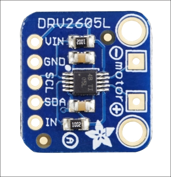
The DRV2605 breakout board (top view) Image courtesy of Adafruit Industries (https://www.adafruit.com)
Vibrators come with various shapes and driving mechanisms. Some of them support haptic feedback while some do not. Before purchasing a vibrator, check the product details carefully to determine whether it supports haptic feedback. For this project, we will be using a simple vibrating mini motor disc, which is a small disc-shaped motor. It has negative and positive leads to connect with the microcontroller board.
The following image shows a vibrator with positive and negative wires soldered:
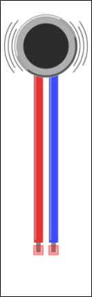
Fritzing representation of a vibrator
Use the following steps to connect the DRV2605 haptic controller to Arduino WiFi Shield:
- Solder headers to the DRV2605 breakout board, connect it to a breadboard and then user jumper wires for the connection to the Arduino.
- Connect the VIN pin of the DRV2605 breakout board to the 5V pin of the Arduino WiFi Shield.
- Connect the GND pin of the DRV2605 breakout to the GND pin of the Arduino WiFi Shield.
- Connect the SCL pin of the DRV2605 breakout board to the Analog 5 (A5) pin of the Arduino WiFi Shield.
- Finally, connect the SDA pin of the DRV2605 breakout board to the Analog 4 (A4) pin of the Arduino WiFi Shield.
The following image shows the connection between DRV2605 breakout board and Arduino WiFi shield:
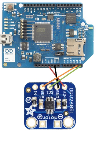
Image courtesy of Arduino (https://www.arduino.cc) and license at http://creativecommons.org/licenses/by-sa/3.0/, and Adafruit Industries (https://www.adafruit.com)
On the DRV2605 breakout board, you can see two square shaped soldering pads marked as + and - along with the motor text label. This is the place where we are going to solder the vibrator. Generally vibrators have two presoldered wires, red and black.
- Solder the red wire of the vibrator to the + soldering pad of the breakout board
- Solder the blue wire of the vibrator to the – soldering pad of the breakout board
The following image shows the final connection between DRV2605 breakout board, Arduino WiFi shield and the vibrator:

Image courtesy of Arduino (https://www.arduino.cc) and license at http://creativecommons.org/licenses/by-sa/3.0/, and Adafruit Industries (https://www.adafruit.com)
You can download the latest version of the Adafruit DRV2605 library from the GitHub repository by navigating to the following URL: https://github.com/adafruit/Adafruit_DRV2605_Library.
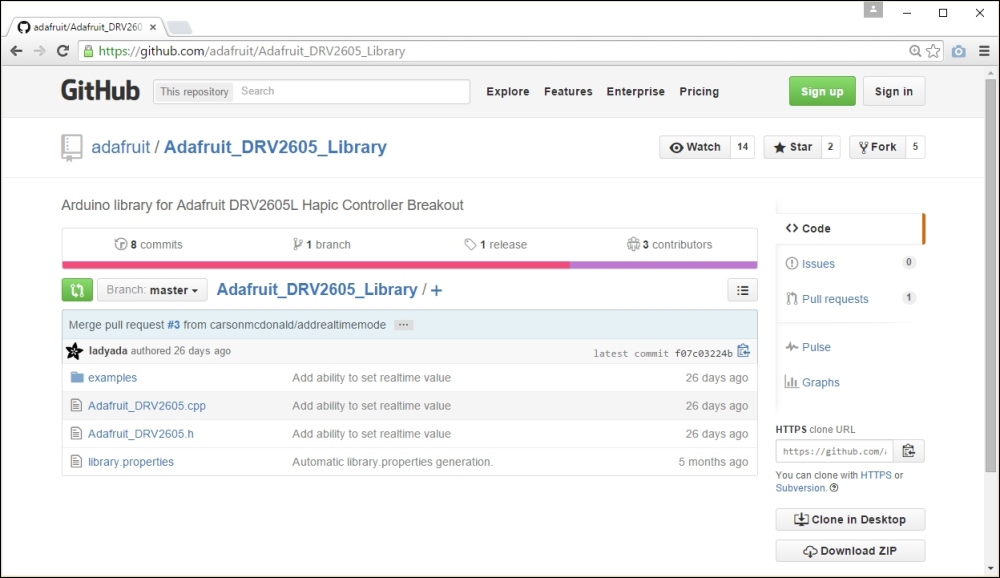
The Adafruit DRV2605 library at GitHub
After navigating to the earlier URL, follow these steps to download Adafruit DRV2605 library:
- Click on the Download Zip button.
- After downloading the ZIP file, extract it to your local drive and rename it as
Adafruit_DRV2605. Then copy or move the folder inside the Arduino libraries folder. Finally, restart the Arduino IDE. - Open the sample sketch included with the library by clicking on File | Examples | Adafruit_DRV2605 | basic and upload it to your Arduino board. The sketch will play 116 vibration effects defined in the DRV2605 library from effect number 1 to 116 in order.
You can download the datasheet for DRV2605 Haptic Driver from http://www.ti.com/lit/ds/symlink/drv2605.pdf and refer to pages 55-56 for the full set of 123 vibration effects. The DRV2605 haptic driver is manufacturing by Texas Instruments.
Now, we will learn how to make different vibration effects depending on the Received Signal Strength Indication (RSSI). Typically, RSSI value rages from 0 to -100. The higher the value, the stronger the signal reception where 0 is the highest value. Therefore, we can logically check the RSSI value return by the WiFi.RSSI() function and play vibration effects accordingly.
In the following example, we will play the first 10 vibration effects according to the RSSI value output by the Arduino WiFi shield. See the following chart for the RSSI value range for each vibration effect:
|
Effect Number |
RSSI | |
|---|---|---|
|
1 |
0 |
-10 |
|
2 |
-11 |
-20 |
|
3 |
-21 |
-30 |
|
4 |
-31 |
-40 |
|
5 |
-41 |
-50 |
|
6 |
-51 |
-60 |
|
7 |
-61 |
-70 |
|
8 |
-71 |
-80 |
|
9 |
-81 |
-90 |
|
10 |
-91 |
-100 |
Following steps shows how to generate different vibration effects according to the RSSI strength of the currently connected Wi-Fi network.
- Open a new Arduino IDE and copy the sketch named
B04844_02_06.inofrom theChapter 2sample code folder. - Modify the following line of the code according to your Wi-Fi network's name:
char ssid[] = "MyHomeWiFi";
- Following line maps RSSI output to the value range from 1 to 10 using the
map()function:int range = map(rssi, -100, 0, 1, 10);
- Set the vibration effect using the
setWaveform(slot, effect)function by passing the parameters such as slot number and effect number. Slot number starts from 0 and effect number can be found in the waveform library effect list. - Finally call the
go()function to play the effect.The following code block shows first how to set and play the waveform
double click – 100%:drv.setWaveform(0, 10); // play double click - 100%drv.setWaveform(1, 0); // end waveform drv.go(); // play the effect!
- Verify and upload the sketch in to your Arduino board. Now touch the vibrator and feel the different vibration effects according to the variations of WiFi signal strength of the currently connected network. You can test this by moving your Wi-Fi router away from the Arduino WiFi shield.
Tip
Downloading the example code
You can download the example code files from your account at http://www.packtpub.com for all the Packt Publishing books you have purchased. If you purchased this book elsewhere, you can visit http://www.packtpub.com/support and register to have the files e-mailed directly to you.