
Stack up your Arduino Ethernet Shield with the Arduino board as you did in the previous chapters and perform the following steps:
- Connect your TTL Serial Camera module with the Arduino and Ethernet Shield as shown in the diagram below. Here, we will use two Arduino digital pins and a Software Serial port to communicate with the camera.
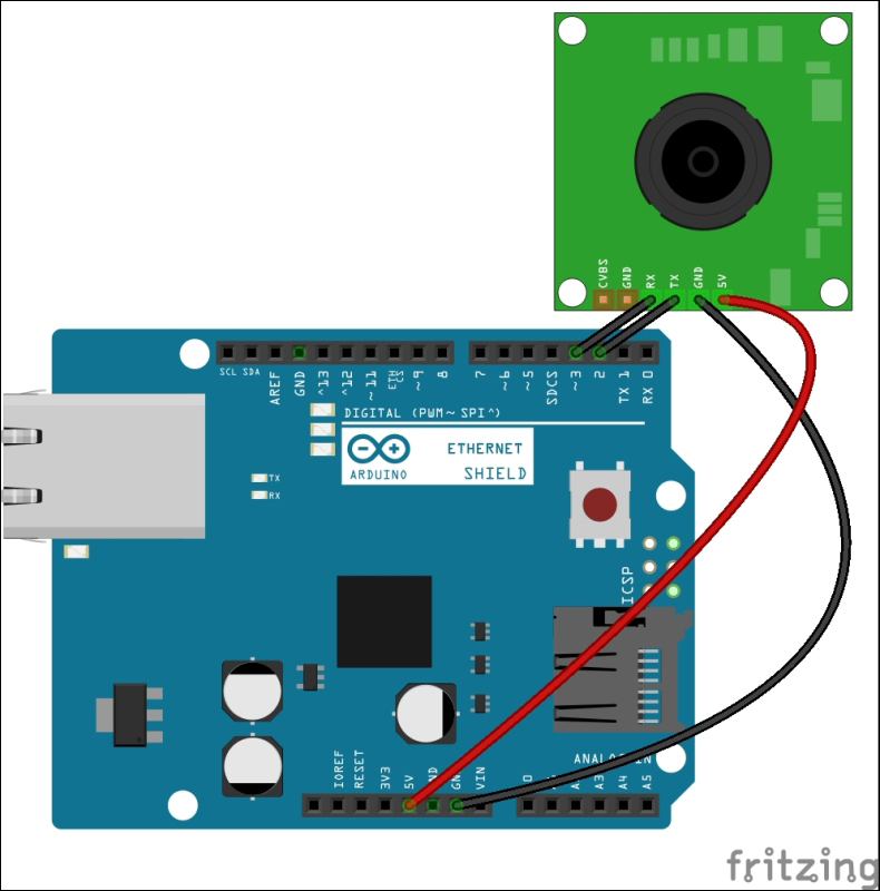
The Adafruit VC0706 Serial JPEG Camera is connected with Arduino Ethernet Shield
- Connect camera TX to Arduino digital pin 2 and camera RX to Arduino digital pin 3.
- Connect camera GND to Arduino GND and camera 5V to Arduino 5V.
- Now insert a Micro SD card into the SD card connector on the Ethernet shield. Remember the Arduino communicates with the SD card using digital pin 4.
- Download the Adafruit VC0706 camera library from GitHub by navigating to https://github.com/adafruit/Adafruit-VC0706-Serial-Camera-Library. After it has been downloaded, extract the ZIP file into your local drive.
- Next, rename the folder
Adafruit-VC0706-Serial-Camera-LibrarytoAdafruit_VC0706, and move the renamedAdafruit_VC0706folder to the libraries folder. Note that the libraries folder resides in the Arduino IDE folder.Alternatively, in the recent version of Arduino IDE, you can add a new library ZIP file by navigating to Sketch | Include Library | Add .ZIP Library…. Then, browse the ZIP file and click on the Open button. This will add the particular library to the Arduino libraries folder.
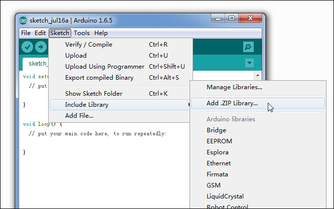
Including a new library by a ZIP file
- Finally, restart the Arduino IDE.
The Adafruit VC0706 camera library includes sample sketches for image capturing and motion detection. You can verify them by navigating to File | Examples | Adafruit VC0706 Serial Camera Library.
You can capture and save images in a Micro SD card using the Adafruit VC0706 camera library. Use the following steps to play with the sample sketches that ship with the Adafruit VC0706 camera library:
- Open the Arduino IDE and go to File | Example | Adafruit_VC0706 | Snapshot.
- Upload the code on your Arduino board. (Also, you can copy the code
B04844_04_01.inofrom theChapter 4code folder) - Once uploaded, the camera will capture and save an image in the SD card with a resolution of 640 x 480. On the Arduino serial monitor, you can see some useful information about the image that is taken, such as the image resolution, image size in bytes, and the number of seconds taken to capture and save the image, which is in the JPG format.
Press the Arduino RESET button to capture the next image. You can use the RESET button to capture any subsequent images. But this sketch is limited to capturing images up to 100 times.
Insert your Micro SD card into the card reader of your PC, browse the SD card, and open the images using any image viewer installed in your computer. Cool!
Now, we will look into some important points of this sample code in the next section so that we can modify the code according to our requirements.
Arduino comes with hardware serial enabled, where pins 0 and 1 can be used to communicate with the serial devices. Pin 0 transmits (TX) the data to out and pin 1 receives (RX) data to in. However, using the Software Serial library, you can convert any digital pin in to TX or RX. For this project, we will use digital pins 2 for RX and 3 for TX.
SoftwareSerial(RX, TX)
The following code snippet shows how to use the Software Serial library to convert Arduino digital pin 2 as RX and digital pin 3 as TX:
// On Uno: camera TX connected to pin 2, camera RX to pin 3:
SoftwareSerial cameraconnection = SoftwareSerial(2, 3);
The following code snippets show the important sections of the Arduino sketch.
To create a new object using the Adafruit_VC0706 class, write a code line similar to the following. This will create the object cam:
Adafruit_VC0706 cam = Adafruit_VC0706(&cameraconnection);
The camera module can be used to take images in three different sizes. The largest size of the image we can take is 640 x 480. In the following code snippet, the camera will capture images in resolutions of 640 x 480. Uncomment the line you want to set as the image size.
// Set the picture size - you can choose one of 640x480, 320x240 or 160x120
 // Remember that bigger pictures take longer to transmit!
 cam.setImageSize(VC0706_640x480);  // biggest
 //cam.setImageSize(VC0706_320x240);  // medium
 //cam.setImageSize(VC0706_160x120);   // small
The takePicture() function of the cam object can be used to take a picture from the camera.
if (! cam.takePicture())
    Serial.println("Failed to snap!");
  else
    Serial.println("Picture taken!");
...
Then, create a filename for the new file by looking at the existing files stored in the SD card.
Finally, write the new image file on the SD card. This process is quite complicated and time consuming.