Do you want to synchronize your Arduino board memory with cloud memory? Then this is the solution for memory mapping between Arduino and cloud. The memory mapping is done by mirroring or replicating a small part of Arduino's memory into the cloud's memory. So, reading or writing on the cloud's memory will have the same effect as reading or writing directly into the Arduino's memory.
The objective of this project is to log the voltage values generated by a solar cell against the time.
In this chapter, you will learn:
- About NearBus Cloud connector
- How to wire a solar cell with Arduino, and the use of the voltage divider
- How to install and use NearAgent with Arduino
- How to configure Xively with Arduino Ethernet
- How to combine NearBus with Xively
- How to display real time voltage logging with Xively
- How to write a simple HTML web page to display real time voltage logging that can be run on your mobile phone
We will use the following hardware to build the circuit:
- Arduino Ethernet board (https://www.sparkfun.com/products/11229) or Arduino UNO (https://www.sparkfun.com/products/11021), with Arduino Ethernet Shield (https://www.adafruit.com/products/201)
- A solar cell (https://www.sparkfun.com/products/7840)
- Two resistors (resistor values should be calculated on the open voltage of the solar cell); take a look at the Building a voltage divider section that follows for the calculation of values and color codes
- Some hook-up wires
- A 9V DC 650mA wall adapter power supply (https://www.sparkfun.com/products/10273)
- DC barrel jack adapter (https://www.sparkfun.com/products/10811)
- An Ethernet cable (https://www.sparkfun.com/products/8915)
Also, you will need a computer with an Arduino IDE installed.
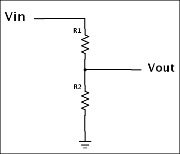
A voltage divider is a simple circuit that can be used to turn higher voltage into lower voltage through a series of two resistors. The resistor values depend on the input voltage and the mapped output voltage:
For this project, we are using Sparkfun Solar Cell Large—2.5W (PRT07840). The open voltage of this solar cell is 9.15V (take a look at the datasheet for open voltage specification).
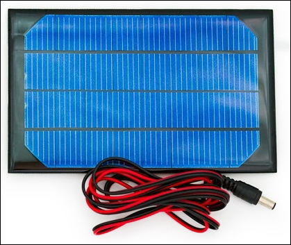
SparkFun Solar Cell Large - 2.5W Image courtesy of SparkFun Electronics (https://www.sparkfun.com)
So, we can calculate the resistor values for the voltage divider by using the following equation:
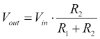
- Vout is 5V (the input voltage to Arduino)
- Vin is 9.15V (the output voltage from the solar cell)
Therefore, the following can be derived:
- R1 = 1200 Ohm = 1.2k (brown, red, red)
- R2 = 1500 Ohm = 1.5k (brown, green, red)
The following Fritzing diagram shows how to connect the voltage divider and solar cell with the Arduino Ethernet board. Now, start building the circuit according to the following diagram and steps provided:
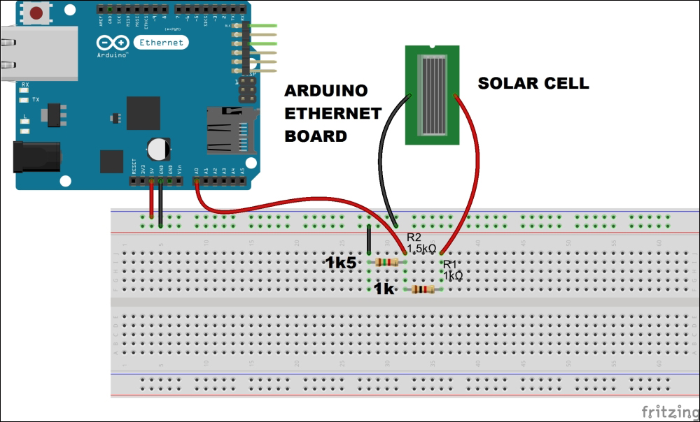
This particular solar cell comes with a DC barrel jack plug attached, and it is center positive. Plug it to the DC barrel jack adapter. Now solder two wires to the positive and negative terminals of the DC barrel jack adapter, as shown in the following image:
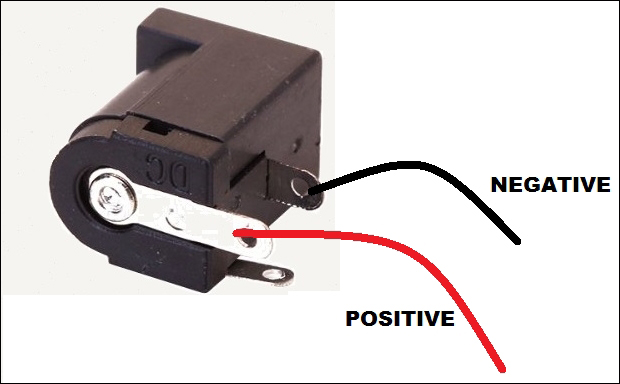
Connect the other wires as explained in the following steps:
- Connect the voltage divider's output (Vout) with the Arduino analog pin 0 (A0).
- Connect the solar cell's positive wire with voltage divider's Vin.
- Connect the solar cell's negative wire to Arduino GND.
- Connect the Arduino Ethernet board to a network switch or router using an Ethernet cable.
- Power the Arduino Ethernet board using a 9V DC 650mA wall adapter power supply.
Now, the circuit and hardware setup is complete, and in the next section you will learn how to set up a NearBus account and connect your Arduino Ethernet shield to the NearBus Cloud for solar cell voltage logging.