
In the previous steps, you learned how to display your water flow sensor's readings and calculate water flow rate and total volume on the Arduino serial monitor. In this step, you will learn how to integrate a simple web server to your water flow sensor and remotely read your water flow sensor's readings.
You can make an Arduino web server with Arduino WiFi Shield or Arduino Ethernet shield. The following steps will explain how to convert the Arduino water flow meter to a web server with Arduino Wi-Fi shield:
- Remove all the wires you have connected to your Arduino in the previous sections in this chapter.
- Stack the Arduino WiFi shield on the Arduino board using wire wrap headers. Make sure the Arduino WiFi shield is properly seated on the Arduino board.
- Now, reconnect the wires from water flow sensor to the Wi-Fi shield. Use the same pin numbers as used in the previous steps.
- Connect the 9VDC power supply to the Arduino board.
- Connect your Arduino to your PC using the USB cable and upload the next sketch. Once the upload is completed, remove your USB cable from the Arduino.
- Open a new Arduino IDE and copy the sketch named
B04844_03_05.inofrom theChapter 3sample code folder. - Change the following two lines according to your WiFi network settings, as shown here:
char ssid[] = "MyHomeWiFi";
char pass[] = "secretPassword";
- Verify and upload the sketch on the Arduino board.
- Blow the air through the water flow sensor using your mouth, or it would be better if you can connect the water flow sensor to a water pipeline to see the actual operation with the water.
- Open your web browser, type the WiFi shield's IP address assigned by your network, and hit the Enter key:
http://192.168.1.177
- You can see your water flow sensor's pulses per second, flow rate, and total volume on the Web page. The page refreshes every 5 seconds to display updated information.
- You can add an LCD screen to the Arduino WiFi shield as discussed in the previous step. However, remember that you can't use some of the pins in the Wi-Fi shield because they are reserved for SD (pin 4), SS (pin 10), and SPI (pin 11, 12, 13). We have not included the circuit and source code here in order to make the Arduino sketch simple.
Typically, the direction of the water flow is indicated by an arrow mark on top of the water flow meter's enclosure. Also, you can mount the water flow meter either horizontally or vertically according to its specifications. Some water flow meters can mount both horizontally and vertically.
You can install your water flow meter to a half-inch pipeline using normal BSP pipe connectors. The outer diameter of the connector is 0.78" and the inner thread size is half-inch.
The water flow meter has threaded ends on both sides. Connect the threaded side of the PVC connectors to both ends of the water flow meter. Use a thread seal tape to seal the connection, and then connect the other ends to an existing half-inch pipeline using PVC pipe glue or solvent cement.
Make sure that you connect the water flow meter with the pipe line in the correct direction. See the arrow mark on top of the water flow meter for flow direction.
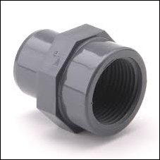
BNC pipe line connector made by PVC
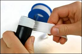
Securing the connection between the water flow meter and BNC pipe connector using thread seal

PVC solvent cement. Image taken from https://www.flickr.com/photos/ttrimm/7355734996/