
Now, you can define a new device with the NearBus cloud connector. In this chapter, we will work with the Arduino Ethernet board. If you have an Arduino Ethernet Shield, you can stack it with an Arduino board and test it with the samples provided in this chapter.
- On the NearBus website menu bar, click on New Device. You will be navigated to the NEW DEVICE SETUP page.
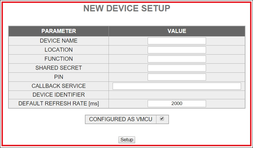
- You can enter a value for each parameter and the only mandatory field is SHARED SECRET. It is eight characters long. Other fields are optional.
DEVICE NAME (Maximum 18 characters)
Arduino EthernetLOCATION
FUNCTION
SHARED SECRET
12345678PIN
CALLBACK SERVICE
DEVICE IDENTIFIER
DEFAULT REFRESH RATE [ms]
- Click on the Setup button.
After setting up the new device, you will navigate to the DEVICE LIST page. The NearBus system will assign a DEVICE ID to your new device and display your device name under the device alias. However, your new device will not have been mapped with NearBus. The mapped status shows as DOWN, which is highlighted in the following:
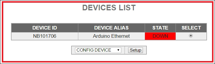
You will need this DEVICE ID when you write an Arduino sketch for this device.
Later, you can visit to the device list page by clicking on Device List on the menu bar.
To use your Arduino Ethernet Shield, or Arduino Ethernet board with the NearBus cloud connector, you must download and install the NearAgent code library. You can download the latest version of the NearBus library for Arduino at http://www.nearbus.net/v1/downloads.html. Also, you can visit the download page by clicking on Downloads on the NearBus web page menu bar. The following screenshot shows the Download page:
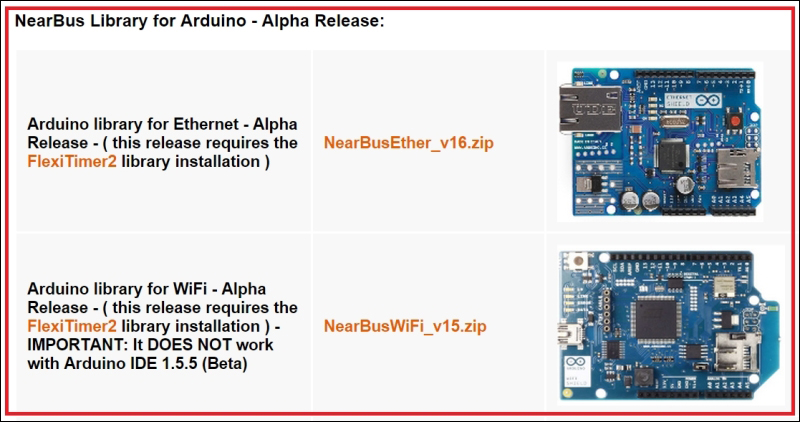
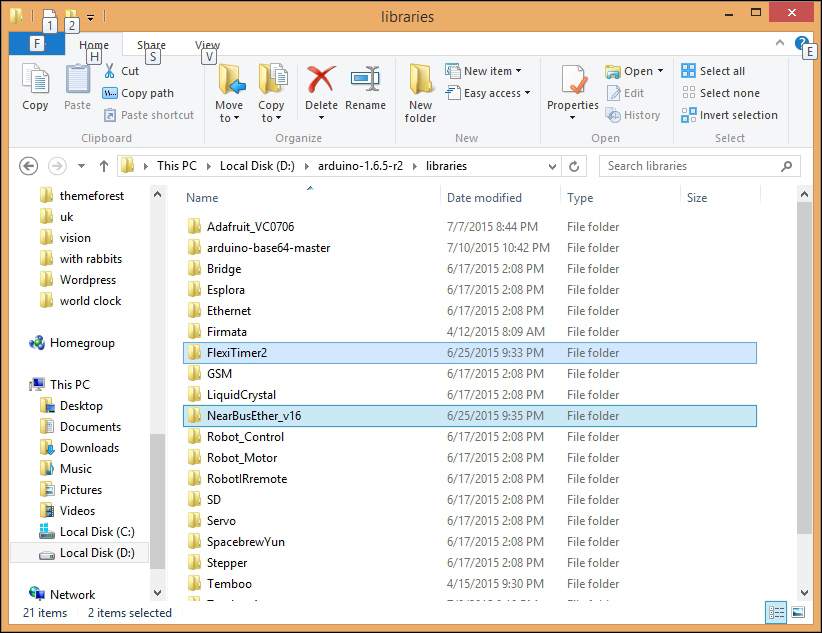
For this project, we need Arduino library for Ethernet, and the latest version is 16. Click on the NearBusEther_v16.zip link to download the library, or type http://www.nearbus.net/downloads/NearBusEther_v16.zip on your browser's address bar and hit Enter to download it on your computer's hard drive. Then, extract the downloaded ZIP file into the Arduino libraries folder.
Also, you need to download the FlexiTimer2 from http://github.com/wimleers/flexitimer2/zipball/v1.1 and extract the ZIP file into the Arduino libraries folder. You can read more about the FlexiTimer2 at https://github.com/wimleers/flexitimer2, which is the GitHub page, and you can even download it from there.
Perform the following steps to modify the sample code to read the voltage:
- Open your Arduino IDE.
- In the menu bar, click on File | Examples | NearBusEther_v16 | Hello_World_Ether. The sample code will load into the Arduino IDE. Also, you can copy and paste the sample sketch,
B04844_05_01.ino, into your Arduino IDE which is located in the code folder ofChapter 5. - Save the sketch in another location by selecting File | Save As from the menu bar. Now, make the following modifications to the sample code to work with your Arduino Ethernet board or Ethernet Shield.
- Modify the following code lines with your NearBus configuration's Device ID and Shared Secret. The Device ID can be found at the Device List page:
char deviceId []    = "NB101706"; // Put here the device_ID generated by the NearHub ( NB1xxxxx )

char sharedSecret[] = "12345678"; // (IMPORTANT: mandatory 8 characters/numbers) - The same as you configured in the NearHub
- Replace the MAC address with your Arduino Ethernet board's MAC address:
byte mac[6] = { 0x90, 0xA2, 0xDA, 0x0D, 0xE2, 0xCD }; // Put here the Arduino's Ethernet MAC - Comment the following line:
//pinMode(3, OUTPUT);
- Then, uncomment the following line:
///////////////////////////////////
    // Example 1 - Analog Input
    // Mode: TRNSP
    ///////////////////////////////////
    A_register[0] = analogRead(0); // PIN A0
Remember, our solar panel is connected to the Arduino analog pin, 0 (A0). But you can attach it to another analog pin and make sure that the pin number is modified in the sketch.
- That's all. Now, connect your Arduino Ethernet board with the computer using an FTDI cable.
- Select the board type as Arduino Ethernet (Tools | Board | Arduino Ethernet), and select the correct COM port (Tools | Port).
- Verify and upload the sketch into your Arduino Ethernet board.
- Now, revisit the DEVICE LIST page. You can see the Device's STATE is changed to UP and highlighted:
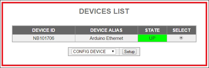
Now, your Arduino Ethernet Shield's internal memory is correctly mapped with the NearBus cloud.
In the next section, we shall learn how to feed our solar panel voltage readings to the Xively and display the real time data on a graph.