
7
Data Center Architecture and Cloud Computing
As an aspiring network professional, you will soon realize how quickly technologies are evolving to support the demand of organizations around the world. Large organizations and service providers are allowing others to lease and rent the resources within their data centers around the world. This allows your organization to simply pay for the resources that are used within another organization’s data center. At the time of writing, many organizations are going into and are already within the data center industry and are becoming cloud service providers.
In this chapter, you will discover how network professionals design enterprise networks to support scalability, fault tolerance and redundancy, security, and Quality of Service (QoS). Furthermore, you will learn how administering and managing your network can be improved by using a controller-based solution that provides the instructions to networking devices within an organization. Additionally, you will explore various technologies that are used to build and maintain a Storage Area Network (SAN) and you will gain a solid foundation in cloud computing and its technologies.
In this chapter, we will cover the following topics:
- Understanding network architecture
- Discovering software-defined networking
- Exploring data center architectures
- Delving into storage area networks
- Fundamentals of cloud computing
Let’s dive in!
Understanding network architecture
As an aspiring network professional, it’s essential to understand the importance of designing an optimal network architecture to support both the current and future demands of an organization. Quite often, many organizations experience a lot of network congestion with too many broadcast messages propagating their network and users complaining about the high latency (slow response times) between their end devices and the servers on the network. Without a proper network design, network security and cybersecurity professionals experience challenges when implementing security solutions and countermeasures to mitigate cyberattacks and threats.
For instance, imagine an organization that’s experiencing a lot of network congestion and security issues within its network. If the organization upgrades its network infrastructure with new networking devices and cabling, it doesn’t necessarily mean its problems are resolved. It all begins with a great network architecture design to ensure various issues such as network congestion, slow response times, security concerns, and network outages are reduced.
When designing a network for an organization, whether it’s a small, medium, or large network, it’s important to consider the following factors:
- Fault tolerance and redundancy
- Scalability
- Security
- QoS
Fault tolerance simply defines the ability of a device to continue functioning and providing its services to a network when one or more components are affected. In other words, a device can continue operating after a component failure has occurred. Networks must be designed with fault tolerance to ensure if a networking device such as when a router or a switch has a failure, the network is built to quickly detect the failure and recover to forward traffic between its source and destination.
The following diagram shows a simple network that supports fault tolerance using redundancy:
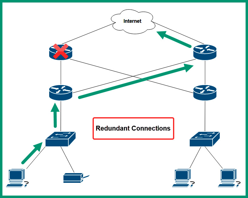
Figure 7.1 – Fault tolerance and redundancy
As shown in the preceding diagram, network professionals can implement fault tolerance on their network by creating redundancy of multiple paths between a source and a destination. Therefore, if a path is no longer available due to a faulty network cable or device, the existing networking devices can detect the failure and redirect network traffic through a different path while ensuring the availability of network services.
Many networks forward traffic using packet switching, which allows a sender to break down a single message into smaller packets to be transported over a shared network. This allows a message such as an email to be broken down into multiple smaller packets that are easier to transport over a network. Each packet contains the necessary source and destination addressing information needed to deliver to the destination host. When using a packet-switching network, each packet may use a different path based on the current network conditions such as available bandwidth, reliability, and load on the network. With a fault tolerance network that uses redundancy, packet switching is possible and provides better delivery of messages from the source to the destination.
Scalability is another important factor that needs to be considered by network professionals when designing or upgrading a network for an organization. Implementing scalability allows a network to easily grow to support new devices, applications, and services while not impacting the performance of existing services that are being accessed by current users within the organizations. Organizations grow as they hire additional staff members to support the demands of their products and services. As more users join the network, so does the number of devices such as computers, laptops, and smart devices. Network professionals will implement additional switches to allow new end devices to connect to the network, allowing users to access the resources and services.
However, if the original network design did not support scalability, network professionals may daisy-chain multiple switches together with the concept of providing a connection to all devices on the network. The following diagram shows an example of multiple switches daisy-chained together:
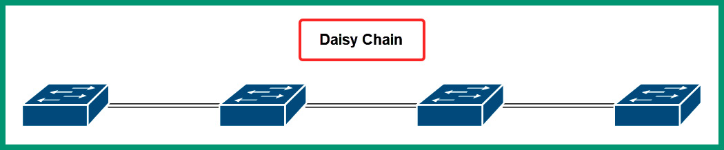
Figure 7.2 – Daisy chain network connections
As shown in the preceding diagram, each network switch is connected to another switch in a daisy-chain effect. While this method of interconnecting networking switches will provide end-to-end connectivity of devices on a network, it does not efficiently support scalability and redundancy. If any of the switches were to experience a failure, connectivity along the daisy chain would be affected, so interconnecting network switches using the daisy chain method is not recommended as it will lead to additional issues in the future.
Security is needed within all organizations in all industries around the world. With the increase in cyberattacks and newly emerging threats, organizations need to safeguard their assets from threat actors such as hackers. Designing a network to support network security and cybersecurity solutions is needed. Security solutions such as firewall appliances, Intrusion Prevention Systems (IPSs), and endpoint security solutions are simply forms of security solutions needed for organizations to mitigate again cyberattacks.
Without network security solutions within an organization’s network, the network professionals will not be aware of their network and assets being compromised by a hacker until it’s too late. Organizations that invest in their network security and cybersecurity solutions are reducing the time to detect an intrusion and are continuously working on improving their security solutions and protecting their assets.
Quality of Service (QoS) is a common technology that allows network professionals to configure networking devices such as routers and switches to prioritize network bandwidth for specific traffic types. Many application layer protocols use Transmission Control Protocol (TCP) as it provides guaranteed delivery of messages between a source and destination. However, many other protocols use User Datagram Protocol (UDP) as their preferred transport layer protocol. UDP is connectionless and has no guarantee that datagrams will be delivered. Because of this, if a network becomes congested, messages sent using UDP have a higher probability of being discarded.
Many traffic types are time-sensitive and need to be delivered as soon as possible within an organization such as Voice over IP (VoIP) and Video over IP. Many organizations have been investing a lot of money into their collaboration solutions such as telepresence, allowing employees to use both VoIP and Video over IP solutions to communicate in real time with each other beyond borders. Imagine if the packets are not being delivered in real time and some are dropped off the network due to congestion; the employee on the receiving end of the call will not be receiving the message in real time and parts of the conversation will be lost on the network. To solve this issue, QoS is implemented on the network to ensure specific traffic types are guaranteed allocated network bandwidth for prioritization over other network traffic types.
Creating a network architecture for an organization seems to be a difficult process as you need to consider a model that supports scalability, fault tolerance and redundancy, security, and QoS. To save the day, Cisco has a wide range of validated design guides that help network professionals to use a proof of concept (POC) model with best practices and recommendations to implement a suitable network design within their organization.
Over the next few sub-sections, you will explore two common models from the Cisco-validated design guides that are used within enterprise organizations. These are the Cisco 3-tier and 2-tier architectures.
Cisco 3-tier architecture
A very common network architecture that is found within many large organizations is the 3-tier architecture, which contains three layers of network switches. Each layer has a specific role and function that adds simplification to the network design and helps network professionals easily add, expand, and manage the network.
The following diagram shows the 3-tier architecture module:
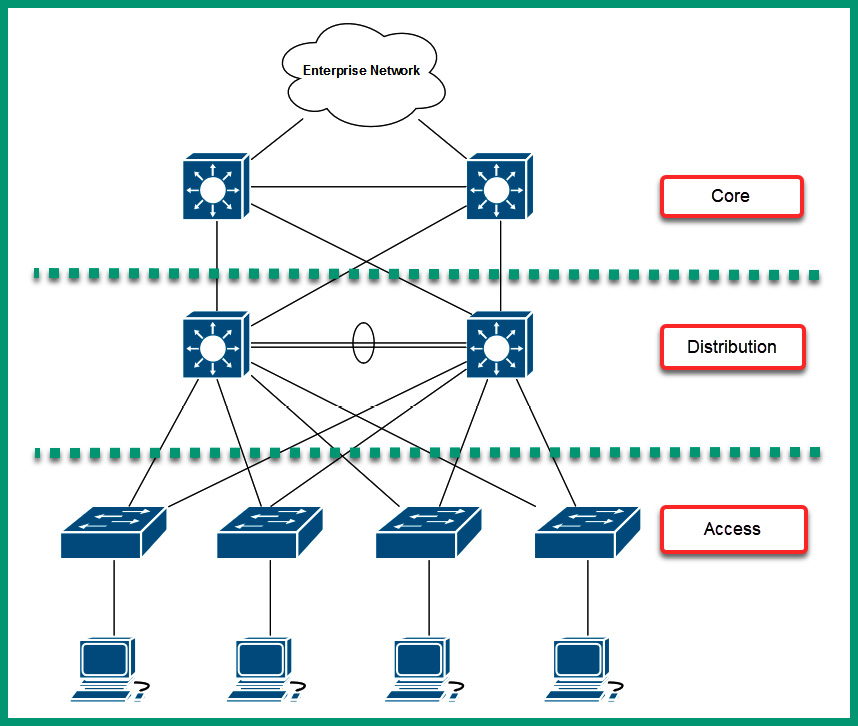
Figure 7.3 – 3-tier architecture
The access layer, also known as the edge layer, is responsible for providing network connectivity and access from end devices to the network and resources. Typically, network professionals implement access layer switches that operate at Layer 2 of the Open Systems Interconnection (OSI) and Transmission Control Protocol/Internet Protocol (TCP/IP) network models. At the access layer, there is no redundancy for end devices that are connected to the network as a typical computer has a single Network Interface Card (NIC) that uses a wired connection to the network switch.
The distribution layer, also known as the aggregation layer, is responsible for providing link aggregation and redundancy for the access layer switches on the network. There are usually two distribution layer switches within a branch office; each access layer switch will connect to each distribution layer switch to ensure redundancy between end devices. In the event a distribution layer switch is offline/unavailable, the access layer switch can automatically detect that a path is no longer available and forward the frames to another distribution layer switch on the network. Typically, traffic within a branch office/network flows between the access and distribution layers.
Important note
Layer 3 switches are implemented within the Distribution and Core layers of the network architecture as they provide both Layer 2 and Layer 3 functionality such as routing.
The core layer is notably the high-speed backbone of the network architecture. It provides interconnectivity and redundancy for the distribution layers within an organization with many branch offices. Therefore, network traffic is sent to the core layer when the destination is located in another branch office.
The following diagram provides a physical topology of the 3-tier architecture:
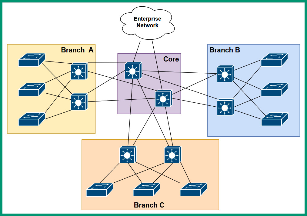
Figure 7.4 – Physical topology of the 3-tier architecture
As shown in the preceding diagram, each branch office has two distribution layer switches that interconnect each access layer switch. If the Local Area Network (LAN) within Branch A needs to expand as more users are joining the organization, the network professional can simply implement another access layer switch to support the additional users and devices at the location, hence it’s easy to scale the network to support new devices. Furthermore, each distribution layer switch is connected to each core layer switch on the network to ensure there is redundancy within the organization. Lastly, the core layer is used to interconnect each branch office together and forward traffic to the routers and the internet.
The following screenshot shows the product page of various types of switches on Cisco’s website:
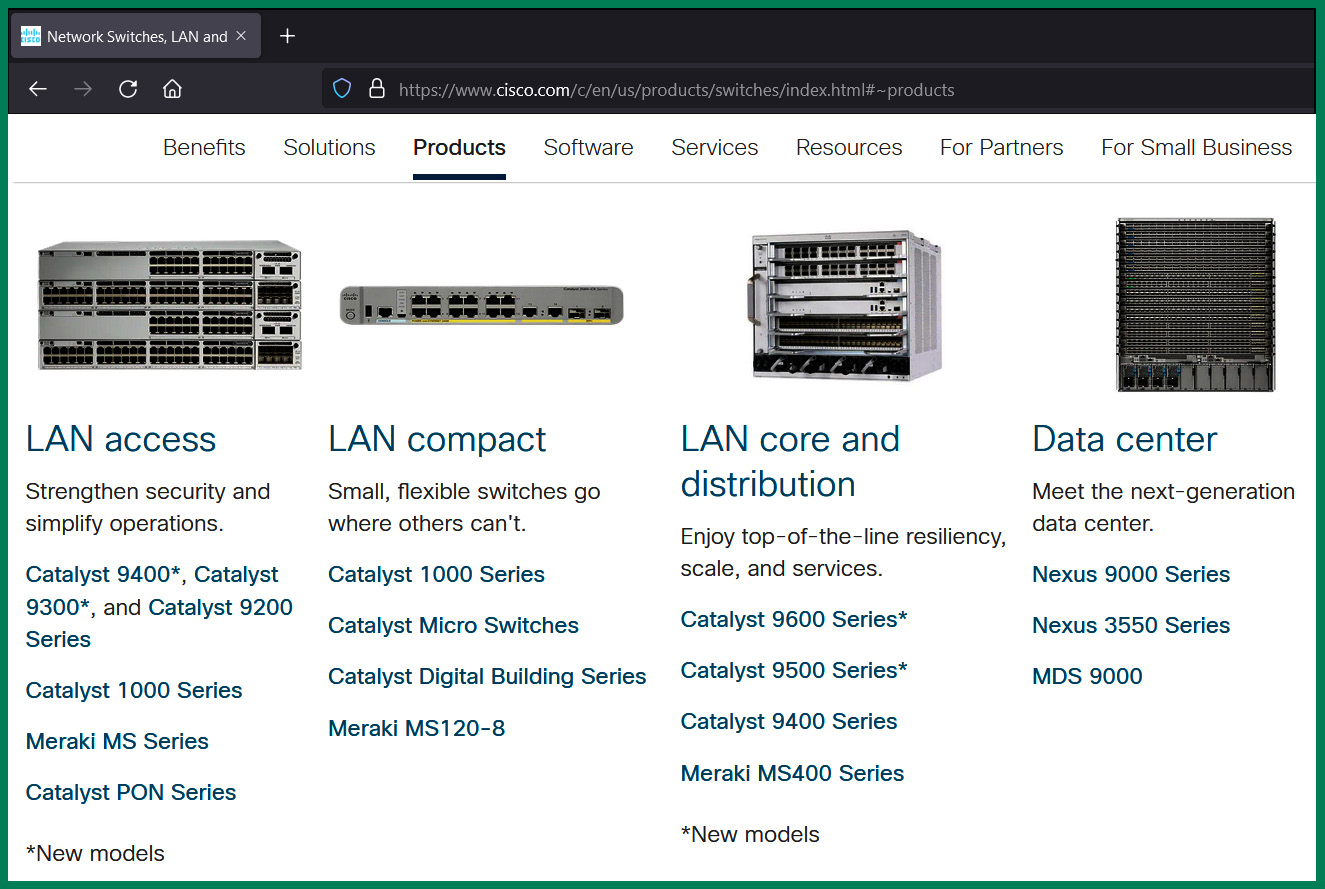
Figure 7.5 – Cisco switches
As shown in the preceding screenshot, there are various types of switches for specific segments of a network such as access layer switches and distribution and core layer switches. Therefore, when acquiring a network switch for an organization, it’s important to determine which type of switch and model is suitable and meets all the requirements to provide the services and features to support the network, applications, and users.
Tip
Each series and models of switches have a data or product sheet that contains all the specifications of the device. As an aspiring network professional, ensure you visit the vendor website for the device details and become familiar with the datasheet of the device to determine if it’s a suitable device needed by your organization or network solution.
The 3-tier architecture has a lot of benefits for large organizations, such as the following:
- Uses a multi-layered design to support scalability and redundancy while ensuring each layer is defined by its role and function
- Support modularity to help network professionals with their design elements, which can be replicated and applied within their entire organization while being consistent
- Eliminates the flat-network design, which does not support scalability and redundancy for large enterprise organizations
Tip
To learn more about the Cisco 3-tier architecture design, please go to https://www.cisco.com/c/en/us/td/docs/solutions/CVD/Campus/cisco-campus-lan-wlan-design-guide.html.
While the 3-tier architecture is recommended as it provides scalability, fault tolerance, and redundancy, it can be quite costly to implement within smaller organizations. Therefore, the 2-tier architecture is designed to provide the same characteristic as the 3-tier architecture for smaller organizations.
Cisco 2-tier architecture
The 2-tier architecture is designed for smaller organizations that have a smaller network and budget. The 2-tier architecture consists of two layers instead of three. The 2-tier architecture provides the same benefits as the 3-tier model such as support for scalability, fault tolerance and redundancy, security, and QoS but with a smaller design.
The following diagram shows the 2-tier architecture:
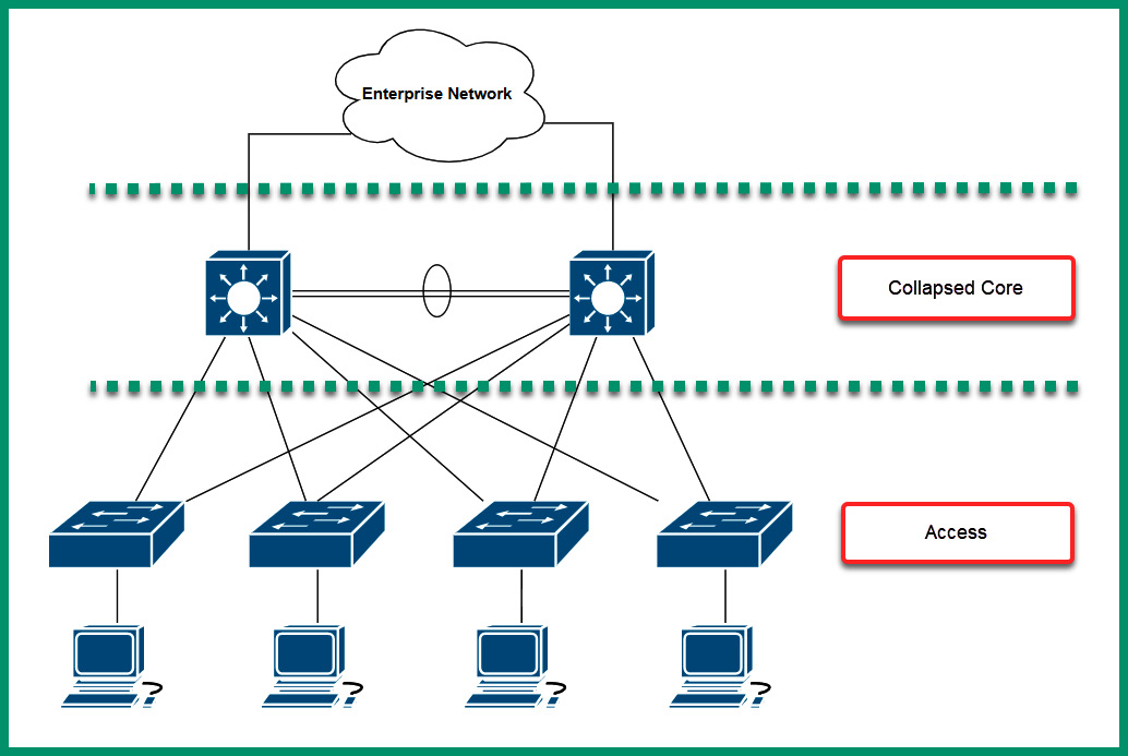
Figure 7.6 – 2-tier architecture
As shown in the preceding diagram, the 2-tier architecture contains a collapsed core layer and access layer. The collapsed core layer is simply a consolidation of the core and the distribution layers into a single layer. Typically, network professionals can implement either core or distribution layer switches within the collapsed core layer of the network. Furthermore, the access layer has the functionality to provide network connectivity of end devices to the actual network. Lastly, keep in mind that each access layer switch is connected to each switch within the collapsed core layer to provide fault tolerance and redundancy.
Having completed this section, you have gained an understanding of both the 3-tier and 2-tier network architectures, which are commonly used within small to large organizations. In the next section, you will take a deep dive into software-defined networking concepts and technologies.
Discovering software-defined networking
Software-defined networking (SDN) allows network professionals to automate the configurations and management of networking devices within an organization using a controller-based solution. Traditionally, a network professional will need to acquire networking devices such as routers and switches from the vendor, unbox each device, perform operating system and firmware upgrades, apply configurations on each networking device, and verify that the configurations are working as expected. This process seems quite normal as it’s the traditional method that’s been adapted for many years within the networking industry.
The downside of using the traditional method is that many tasks seem to be a bit repetitive and time-consuming, and let’s not forget the network professional needs to manually configure each switch and router. One of the issues that occurs during manual configurations of networking devices is that the network professional can make human errors, such as misconfiguring features and services on the device. Additionally, many seasoned network professionals will create a template, which consists of a set of configurations needed for specific devices. However, these templates can contain issues such as outdated configurations and not applying them to specific device models on the network.
An alternative is using programming techniques to automate the process of applying configurations to networking devices over a TCP/IP network. Network professionals can use Python, a high-level programming language to create scripts, which retrieves information about a networking device from various sources such as Microsoft Excel workbooks and network monitoring applications. Such information includes hostnames, IP addresses, subnet masks, and so on. Additionally, using a template engine for Python such as Jinga2 allows network professionals to create templates that automate the process of applying configurations to networking devices.
Tip
To learn more about Jinga, take a look at https://palletsprojects.com/p/jinja/ and https://jinja.palletsprojects.com/.
Within a Cisco environment, Zero Touch Provisioning allows network professionals to configure a new networking device such as a Cisco switch or router to automatically retrieve configurations when it’s connected to a network. This saves time and reduces the likelihood of misconfigurations on new networking devices.
While these methods seem a lot better than manually configuring networking devices, these still require a lot of manual work without you realizing it. The network engineering industry is adapting to controller-based solutions, which allow network professionals to centrally manage an entire network from a single pane of glass (dashboard). Therefore, network professionals no longer need to apply configurations manually to network devices – they can simply apply their intent to an SDN controller and the controller will apply the necessary configurations on the network. This is known as intent-based networking (IBN). Next, you will explore the components that are used within an SDN environment.
Components of SDN
In a traditional network architecture, each networking device makes its own decisions on how to forward a message to a destination. Simply put, each networking device has a brain that makes the choices and decisions on forwarding messages and has its set of configurations. Since networking devices on a traditional network operate autonomously from each other, it’s important to understand the role and functions of the three planes that exist within each networking device:
- Management plane
- Data plane
- Control plane
The management plane is responsible for allowing network professionals to manage network devices using various communication channels and protocols. Some management protocols include Secure Shell (SSH), Hypertext Transfer Protocol Secure (HTTPS), and Simple Network Management Protocol (SNMP). Without the management plane on a networking device, it would be quite difficult to manage and monitor a device over a network.
The data plane on a networking device is responsible for receiving and forwarding messages between a source and a destination. When a message is received by a switch, the destination Media Access Control (MAC) address is inspected within the frame header. The switch will check the Content Addressable Memory (CAM) table or MAC address table to determine how to forward the frame to its destination. Additionally, a router will inspect the packet header for the destination IP address and check its local routing table for a suitable path to forward the packet to its destination.
The control plane on a networking device is responsible for controlling how the entire device operates. The control plane is the actual brain of the device and tells it how to make its forwarding decisions on the network. Various routing protocols help routers determine how to forward a packet to a destination, while switches use various Layer 2 forwarding algorithms for determining how to forward a frame to a destination host on the network. All the algorithms and mechanisms that are responsible for determining how a device handles messages exist within the control plane.
Within an SDN architecture, the SDN controller manages the control plane’s role and functionality for all the networking devices. Simply put, the control plane (brain) function is no longer handled by each networking device – the function is now controlled and managed by the SDN controller, as shown in the following diagram:
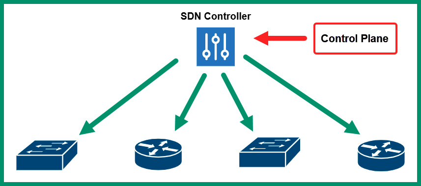
Figure 7.7 – SDN architecture
Using an SDN within a large network allows network professionals to log into the SDN controller, which provides full visibility of everything on their networks, such as the health and performance of the network and devices. The SDN controller can predict potential network issues and provide recommendations on how to resolve them and implement proactive solutions. Furthermore, using the SDN controller allows network professionals to centrally manage all networking devices within their entire organization from a single dashboard interface.
The SDN controller can manage all the networking devices by using the Southbound Interface (SBI) application programming interface (API). The SBI simply utilizes the following methods to manage a networking device:
- NETCONF
- OpenFlow
- Command-line interface (CLI)
- SNMP
- OpFlex
Additionally, the network professional can access the SDN controller via the Northbound Interface (NBI) API, which provides visibility of the entire network through a single pane of glass (dashboard). Practically speaking, network professionals access the user interface of the SDN controller by using a Graphical User Interface (GUI) or retrieving information using a Representational State Transfer (REST) API.
The following screenshot shows the user interface of the Cisco Digital Network Architecture (DNA) Center:
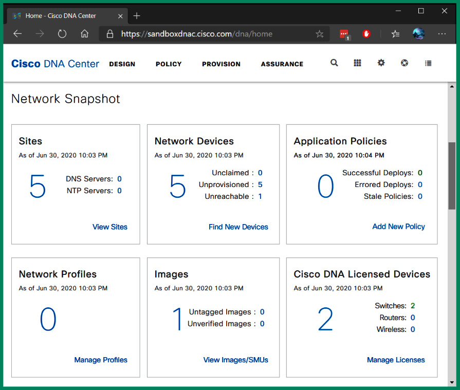
Figure 7.8 – Cisco DNA Center
Cisco DNA Center is an SDN controller that allows networking professionals to design and implement policies, perform device provisioning tasks, and continuously monitor their network for performance issues.
Having completed this section, you have learned about the importance and benefits of using SDN technologies within networks and how network professionals reduce the time of identifying and resolving issues while using a proactive approach. In the next section, you will discover various data center architectures.
Exploring data center architectures
A data center is a dedicated building or a group of buildings that contains a huge collection of servers, networking devices, and security appliances that are maintained by an organization. Medium and large organizations create a data center that allows IT professionals to house all their servers and critical applications within a dedicated space on their network. This concept allows centralized management and a dedicated facility with proper environmental controls such as Heating, Ventilation, and Air Conditioning (HVAC) systems, multiple internet connections from various Internet Service Providers (ISPs), redundant power supplies to support the availability of resources needed by the organization, and so on.
While the idea of owning a data center is amazing, it’s quite costly to build and maintain one. However, there are service providers that are building and maintaining data centers to allow customers to simply rent or lease the resources within the data center. For instance, if your organization needs a few servers to host your critical applications and resources but does not have the physical space to store the servers, you can simply place your servers within a data center that’s owned by a service provider. Next, you will explore branch versus on-premises solutions for housing a data center.
Branch office versus on-premises
Why would an organization need a data center? Organizations use servers to host their mission-critical applications and provide services and store large amounts of data. As productivity increases and new applications are needed, the IT team will implement additional servers to ensure all users can easily access the resources when needed. For instance, if an organization has one file server that provides centralized storage to hundreds of users on the network, as more users attempt to transfer files between their computers and the file server, the server will become overwhelmed. Simply put, the server will need to handle all the requests from each user simultaneously, which uses a lot of computing power. Furthermore, if the server is unavailable on the network, users will not be able to access the files stored on the server.
One approach is to implement redundant servers within the organization so that there is more than one server to provide the same services, allowing fault tolerance and redundancy of resources. However, as the number of servers increases within an organization, the IT team has to ensure all their assets, such as the servers, are always available to users on the network. This means that system administrators and IT technicians need to perform routine maintenance procedures to ensure everything is working fine while actively monitoring the health of each device on the network.
An on-premises solution simply means an organization has its servers within its company’s building and they are maintained by in-house IT professionals. The advantage of using an on-premises model is the IT professionals have physical access to the servers and the organization has full ownership of the devices and equipment. However, if one of the servers has a faulty component or is unavailable, the in-house IT professionals are responsible for resolving the issues as quickly as possible and ensuring users have access to the resources.
As an organization increases and creates more branch offices, the IT team of the company needs to ensure their users, such as the employees, have access to all the network resources to efficiently perform their daily duties. Companies will typically contact their local telecommunication provider or ISP to Wide Area Network (WAN) solution to interconnect their branch offices, such that the users on a remote branch office will be able to access the resources at the main office and so on. Alternatively, the company can implement a Virtual Private Network (VPN) solution to internet their branch offices while removing the cost of paying an ISP for a managed service.
Sometimes, an organization sees the benefits of using a data center from a service provider to host their servers and applications since data centers are designed to provide uptime availability, ensuring resources are always available to users and customers. While hosting your servers and applications in a data center, it’s important to consider the following factors:
- The connectivity methods between the data center and your location
- The security and data privacy concerns of using a data center from a service provider
- The expenses associated with paying a service provider versus an on-premises solution
Colocation is another type of solution that is commonly used by many organizations. A colocation solution is usually a type of data center that allows customers to rent physical server rack spaces, internet bandwidth, servers, and other equipment. Using a colocation allows companies to bring their own devices to the data center’s location, where they will be hosted by the service provider.
Spine and leaf
A data center uses a special 2-tier architecture known as the spine and leaf architecture, which supports scalability and East-West traffic flow. The spine and leaf network architecture contains two layers of network switches that are designed specifically to operate in data center networks. The top row of switches is known as the spine switches or the backbone switches as they are used to create a full mesh by interconnecting each spine switch to all switches within the lower layer, as shown in the following diagram:
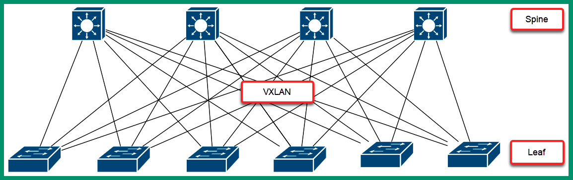
Figure 7.9 – Spine and leaf architecture
Furthermore, the switches on the lower layer are referred to as leaf switches. Each leaf switch is connected to each spine switch, creating a full mesh for redundancy. Additionally, the leaf switches are also known as Top-of-Rack (TOR) switches since they allow servers to connect to the network. The following diagram shows multiple physical servers within multiple racks and that each physical server is connected to a leaf switch:
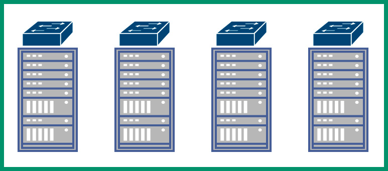
Figure 7.10 – Top-of-Rack switching
As shown in the preceding diagram, each server within a single rack is connected to the TOR switch on the same rack. Therefore, if a virtual machine from one of the servers within Rack 1 wants to communicate with a virtual machine within another server on Rack 1, the TOR switch on Rack 1 will handle forwarding the traffic between servers and virtual machines within Rack 1 only.
Important note
North-South traffic flow occurs between a server and outside the data center, while East-West traffic flow occurs between servers and virtual machines within the data center.
However, if a virtual machine from a physical server on Rack 1 wants to communicate with a virtual machine on a physical server on Rack 3, the TOR switch on Rack 1 will forward the traffic to one of the spine switches, which then forwards the message to the TOR switch on Rack 3, which is responsible for delivering the message to the destination virtual machine. The following diagram shows how the traffic is forwarded between the spine and leaf switches:
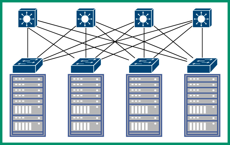
Figure 7.11 – Forwarding traffic between the spine and leaf switches
Each switch within the spine and leaf architecture is a layer 3 switch and uses dynamic routing protocols to forward traffic between servers and devices. This architecture uses a technology known as Virtual Extensible LAN (VXLAN), which allows data centers to easily scale to meet the demands of providing cloud computing services to users. As more server racks are implemented within the data center, the spine and leaf architecture allows data center engineers to easily scale the network to support more devices. Implementing an additional leaf switch allows more servers to join the data center network. Furthermore, it’s easy to implement additional spine switches to support the increase of leaf switches.
Having completed this section, you have learned about the fundamentals of data center architecture and design. In the next section, you will learn about storage area networks.
Delving into storage area networks
Data is the most valuable asset to any organization and needs to be safeguarded at all times from threat actors such as hackers. While cybersecurity professionals work continuously to ensure their organization’s assets are protected, it’s important to consider hardware failures can occur on devices that are storing data such as Hard Disk Drives (HDDs) and Solid State Drives (SSDs) on a computer, server, or Network Attached Storage (NAS).
Imagine if an organization does not have any centralized file server on the network and everyone stored critical files on their local computers. Whenever a user wants to share a document with another person, they would attach the file to an email message. If a user’s computer were to be infected with malware or experience hardware failure, there’s a risk that data will be lost on the local device.
An organization can implement NAS devices on their Local Area Network (LAN), which allows users to centrally store files on a dedicated device over a TCP/IP network. A NAS, as its name suggests, is a small enclosure that contains a few HDDs that operate in a cluster. This allows users on a network to access the storage unit over a computer network. NAS devices are efficient for small networks with a few users as it allows the company to save money while using a dedicated and centralized storage device.
If business is going well for an organization, more employees may be hired as the organization is expanding, which means more users and devices are joining the network. In a larger organization, NAS devices are not efficient to support hundreds or thousands of users who are regularly transferring files over a network. Having dedicated storage servers with lots of storage drives that have been configured using Redundant Array of Independent Disks (RAID) to provide redundancy between the storage drives of a server is essential. Therefore, if one storage fails within the server, the data is not lost.
However, some organizations that have the necessary resources invest in building a SAN to provide a dedicated high-speed network to interconnect all their data storage pools of servers and devices. The concept of a SAN is to ensure high-speed access between users and the dedicated storage servers, as well as provide maximum availability by implementing fault tolerance and redundancy on the storage devices and applications within the SAN.
The following diagram shows a typical SAN design:
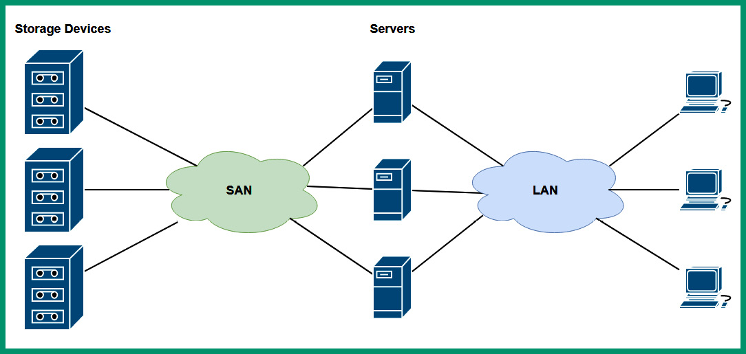
Figure 7.12 – SAN architecture
As shown in the preceding diagram, the SAN contains the dedicated storage servers and disk arrays and uses a fiber channel to ensure there is support for high data rates between the file servers and the users in the organization. Furthermore, there are SAN switches that are dedicated networking devices that interconnect with storage servers and have the responsibility of moving network data through the SAN. Next, you will explore common network connections that are implemented within an SDN environment.
Connection types
Since a SAN supports many storage devices such as servers with various storage arrays, it’s important to ensure that SAN can support the huge bandwidth needed between the SAN and other parts of the organization’s network from users.
The following are various components within an SDN environment:
- Fiber Channel (FC) is simply a very high-speed network that is designed to support very low latency (fast response times) and high throughput between devices. Using an FC within a SAN has many advantages compared to using traditional copper cables. Using an FC allows network professionals to run fiber cables beyond the limitation of 100 meters and transfer data at gigabit speeds compared to copper cables, which experience attenuation (loss of signal) over distance. When implementing FC within a network, an FC Host Bus Adapter (HBA) is installed on each storage server and networking device within the SAN. For each HBA on a device, multiple ports allow data to be exchanged.
- Fiber Channel over Ethernet (FCoE) allows FC frames to be encapsulated within an Ethernet message for transportation over a network. The objective of using Ethernet is to provide a mutual technology over a network that allows multiple traffic types such as FC and Internet Protocol (IP) to be delivered over a high-speed network that uses fiber optic cables. However, access to network resources is usually limited to a LAN.
- Internet Small Computer Systems Interface (iSCSI) allows fiber communication over a routable network compared to FCoE. Simply put, if there are users over different IP networks within the organization, iSCSI is a better solution because FCoE provides access to users on the same network (LAN).
Having completed this section, you have explored the fundamentals of SAN and its components. Next, you will take a deep dive into exploring cloud computing, models, and services.
Fundamentals of cloud computing
Cloud computing is one of the most demanding and trending topics within the IT industry as more organizations are migrating their services, applications, and servers to the cloud. As an aspiring network professional, it’s essential to understand cloud computing, the types of cloud deployment models, and cloud services.
Cloud computing can be demystified as paying for the resources you use within a cloud service provider’s data center. Imagine your organization wants to acquire additional servers to host new applications and services needed by the employees to perform their daily duties. Some of the concerns of acquiring new servers are the time it takes for the vendor to ship the servers to the customer’s location, the time it takes the IT staff members to set up and deploy the applications on the servers, and any additional maintenance on the equipment if any issues should occur in the future.
What if your organization can simply pay for the resources used within someone else’s data center such as Microsoft Azure, Amazon Web Services (AWS), or Google Cloud Platform (GCP)? Simply put, your organization can create a user account on a cloud service provider’s website, select the type of services needed, use the online calculator to get an estimate for the cost of hosting the services on the preferred cloud provider’s data center, and deploy the servers and services within minutes compared to weeks. That’s right – rather than waiting for a few weeks to receive physical servers from a vendor, using cloud computing allows professionals to deploy new servers and applications on the internet within a matter of minutes. Furthermore, if no one wants to use a service, application, or server within a cloud provider’s data center, you can terminate it within seconds and stop paying for it.
Cloud computing providers allow their customers to use a pay-as-you-go model, which means you can pay per minute or hour, depending on the preferred cloud provider. This allows organizations to save a lot of money and time as they can start and stop servers as needed. Most importantly, the customer is not responsible for handling the physical maintenance of the servers within the cloud service provider’s data center, which removes that responsibility from your IT staff. However, the customer is responsible for the security management of any services, applications, and servers that are deployed within any cloud provider’s data center. Hence, cloud engineers need a solid understanding of security concepts and best practices for securing data and assets on the cloud.
The word cloud simply means the customer is using a service, application, or server within a data center that cannot be seen by the customer or is physically accessible. For instance, anyone on the internet with a credit card can create a user account on the Microsoft Azure, AWS, or GCP website and deploy a server within just a few minutes. As a customer, do you see the physical server within the data center? Simply put, in most cases, you do not see the actual servers, but you can communicate with the server using the internet; the internet is a collection of many public networks that are managed by many ISPs around the world.
There are many advantages to using cloud computing technologies, such as the resources within a cloud provider’s data center being accessible from anywhere at any time. For instance, services such as Google Workspace and Microsoft 365 allow companies to outsource their email services to Google and Microsoft cloud solutions. With Google Workspace and Microsoft 365, this eliminates the need for a company to set up mail exchange servers within their networks. Using these email solutions allows a company to simply pay per user per month and if a user needs additional storage on their mailbox, the company can simply pay an additional fee for the specific user. Overall, all users will be able to access their mailbox (email inbox) from anywhere at any time using an internet connection as the services are hosted and maintained by the email solution provider.
Cloud computing helps companies reduce the need for physical appliances, equipment, and devices at their location. Simply put, it reduces the physical space needed to house physical servers. Cloud providers allow their customers to quickly spin up (create) a new virtual server on the cloud within a few minutes while allowing the customer to scale up or scale down the computing resources on the server. As more computing power is needed on a virtual server on the cloud, a customer is provided with features to increase the computing resource, such as increasing the number of virtual processors, memory such as virtual Random Access Memory (RAM), storage drives, and NICs. This is commonly referred to as scaling up. Scaling down is referred to as reducing the computing resources on a server as the demand is lower.
Organizations that use cloud computing technologies reduce the need for a dedicated IT team. However, there is a huge demand for cloud engineers with specialized skills needed to deploy, maintain, and secure solutions on Microsoft Azure, AWS, and GCP. Each of these top cloud providers has developed a learning path and certification tracks to help the new generation of IT professionals to learn cloud computing.
Important note
A tenant is a single customer on a cloud provider platform. Multi-tenant is when multiple customers use the same cloud provider platform. Tenant isolation allows multiple customers to use the same shared resources within the data center but each customer is isolated from accessing another customer’s resources.
Cloud computing providers support elasticity and scalability. Elasticity simply allows a system to adapt to the workload and changes of the environment, such that a customer can quickly provision and de-provision servers and applications as needed within a cloud provider’s data center. For instance, if your organization needs one web application to host a website, as more users connect and interact with your web server, there will be an increase in demand for computing power to process each web request. With elasticity, your organization can create additional web servers within a few minutes with the same web application and implement a load balancer to distribute the inbound web request between each web server.
Scalability within cloud computing allows organizations to increase and decrease the resources needed based on the demand. For instance, you may need one Linux server on the cloud to perform some tasks. As you increase the workload on the server, you will eventually notice that each task takes longer to be completed. Increasing the virtual number of processes and memory can allow more tasks to run at the same time while ensuring each process is allocated sufficient computing resources.
Furthermore, security is everyone’s concern. Within a cloud computing environment, the customer is responsible for managing the security of the resources they place within a cloud service provider’s data center. For instance, if you spin up a new virtual server that runs Windows Server 2022 or a Linux-based server, you are responsible for securing your virtual machine on the cloud. Therefore, if you do not apply device hardening techniques and best practices on the virtual server, there’s a high risk a threat actor such as a hacker can compromise and take over your virtual server on the internet.
Over the next few sub-sections, you will discover various cloud deployment models, service models, and connectivity solutions.
Deployment models
When deploying a cloud computing solution for an organization, four models are commonly used by cloud engineers and service providers. The private cloud model is where any organization such as your company owns the data center, and the infrastructure is managed by your IT team. Within the private cloud model, the resources are only accessible to the employees of the organization and no one else.
The following diagram shows a representation of a private cloud model that can only be accessed by the organization and its employees:
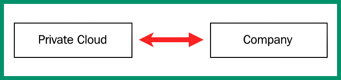
Figure 7.13 – Private cloud model
The public cloud model is available to anyone on the internet. These are public cloud service providers such as Microsoft Azure, AWS, GCP, and many more. The public cloud allows anyone to create virtual servers and deploy applications and services on a data center that shares its resources with others and uses a pay-as-you-go model. In a public cloud model, the cloud service provider is responsible for all physical hardware maintenance.
The following diagram shows a representation of the public cloud and your organization, which is sharing the resources with others:
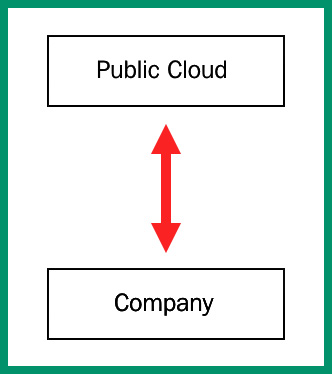
Figure 7.14 – Public cloud model
The hybrid cloud model is a mixture of the private and public cloud deployment models. It allows an organization’s data, servers, and applications to be locally backed up on its private data center and replicated to an online public cloud solution provider. This solution is quite costly to maintain but provides an excellent solution for disaster recovery and business continuity practices.
The following diagram provides a representation of a hybrid cloud deployment model:
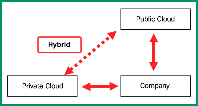
Figure 7.15 – Hybrid cloud model
Lastly, the community cloud model is where several organizations share the resources on a cloud platform. These can be groups of companies with similar interests or partnerships all accessing and sharing resources within a data center or cloud service provider.
Cloud service models
Various cloud service models define how services, applications, and resources are delivered to users from a cloud service provider’s data center. Software-as-a-Service (SaaS) is a very common service model that allows the cloud solution provider to offer access to the user interface of the application that’s being hosted within the cloud provider’s data center. For instance, organizations that use Google Workspace or Microsoft 365 do not need to install the client application on each user’s computer. Each user can simply access the web application on their corporate email and other collaboration tools using a standard web browser. The user is neither concerned nor has access to manage the host operating system or the hardware components of the servers that are hosting the application.
The Platform-as-a-Service (PaaS) service model is designed for developers who require a bit more control over their operating or working environments. When working with a PaaS solution, the cloud service provider allows the user or developer to make changes to the operating system and the programming frameworks that are running on the host operating system. However, the user does have access to the underlying hardware resources on the server.
The Infrastructure-as-a-Service (IaaS) service mode allows the user to manage physical hardware and software resources on the virtual server on the cloud provider’s data center. This model allows the user to increase and decrease the computing resources on servers, such as the number of processes, memory, storage, networking interface, and the operating system.
Desktop-as-a-Service (DaaS) is where a cloud service provider can deliver a virtual desktop environment to a user over the internet. The cloud service provider is responsible for managing all the backend maintenance such as hardware and software requirements. This includes backups and storage and updates. However, security management of DaaS solutions may be a shared responsibility between the cloud service provider and the user. DaaS offers a persistent desktop, which keeps the data and changes made by a user. So, the next time the user logs onto the virtual desktop, everything is already there. In a non-persistent desktop, each time the user logs off from the virtual desktop, all data and settings are cleared from the system. Therefore, the next time the user logs on, a clean virtual desktop environment is presented.
Lastly, the Infrastructure as Code (IaC) model focuses on managing the resources within a cloud service provider’s data center and the virtual machines on servers, load balancers, and networking using the same versioning method as DevOps engineers.
Cloud connectivity solutions
Hosting applications, servers, and other resources on a cloud service provider’s data center is awesome but ensuring your organization and users have secure access is very important. Not having secure access to the resources on your data center or a cloud provider’s data center is a huge security risk. This is because a threat actor can intercept the communication channel between your users and the resources on the cloud, capturing sensitive and confidential information.
Using a VPN allows a secure, encrypted connection to be established over an unsecure network such as the internet. Setting up a VPN between your organization’s network and the resources on a cloud service provider’s data center is a common solution used by many organizations. Using a VPN allows the company to save a lot of money while protecting data-in-motion over the internet. However, the company will be responsible for managing its VPN solutions and ensuring users can access the resources when needed.
Another method for connecting to a cloud service provider’s data center is using a private-direct connection to the cloud provider. Many ISPs provide direct connectivity solutions between an organization (customer) and a data center. These connectivity solutions are usually secure within the ISP network to ensure no unauthorized parties can intercept the communication channel between the customer and the data center.
Having completed this section, you gained the skills and knowledge to identify various cloud computing technologies, service and deployment models, and connectivity methods.
Summary
In this chapter, you learned about the 3-tier and 2-tier network architectures, which are commonly implemented by network professionals within small to large organizations. You have discovered the benefits of using these network architectures to support scalability, fault tolerance and redundancy, security, and QoS. Furthermore, you have explored the fundamentals of SDN and how it helps network professionals to predict potential issues in their network and improves the management of all networking devices. Lastly, you can now describe SAN technologies and cloud computing since you explored various deployment models and their benefits to organizations.
I hope this chapter has been informative for you and is helpful in your journey toward learning networking and becoming a network professional. In the next chapter, Chapter 8, Networking Devices, you will learn about the roles and functions of various networking and networked devices that are commonly found within organizations.
Questions
The following is a short list of review questions to help reinforce your learning and help you identify areas that may require some improvement.
- Which of the following layers allows a server to connect to the network?
A. Core
B. Access
C. Distribution
D. Data Link
- The collapsed core is a combination of which of the following?
A. Core, access, and distribution
B. Core and access
C. Access and distribution
D. Distribution and core
- Which of the following is a benefit of using the 3-tier architecture?
A. Single-layer network
B. QoS
C. Security
D. Scalability
- Which of the following components is responsible for determining how a device forwards traffic on a network?
A. Routing protocol
B. Management plane
C. Control plane
D. Data plane
- Which of the following network architectures is used within a data center?
A. 2-tier
B. Spine and leaf
C. 3-tier
D. All of the above
- Which of the following SAN technologies does not allow access beyond a local area network?
A. IP
B. TCP/IP
C. iSCSI
D. FCoE
- Which of the following cloud models allows an organization to access shared resources with others?
A. Public
B. Hybrid
C. Community
D. Private
- Which of the following service models provides a virtual desktop interface for a user?
A. SaaS
B. DaaS
C. IaaS
D. PaaS
- Which of the following connectivity methods allows an organization to securely access the resources on a data center while saving cost?
A. Leased line
B. VPN
C. Metro Ethernet
D. MPLS
- Which model provides access to the user interface of an application that’s hosted on a cloud provider’s data center?
A. SaaS
B. DaaS
C. IaaS
D. PaaS
Further reading
To learn more about the topics that were covered in this chapter, check out the following links:
- Enterprise Campus 3.0 Architecture: Overview and Framework: https://www.cisco.com/c/en/us/td/docs/solutions/Enterprise/Campus/campover.html
- What is Software-Defined Networking (SDN)?: https://www.vmware.com/topics/glossary/content/software-defined-networking.html
- Cisco Data Center Spine-and-Leaf Architecture: Design Overview White Paper: https://www.cisco.com/c/en/us/products/collateral/switches/nexus-7000-series-switches/white-paper-c11-737022.html
- Why storage area networks are important: https://www.ibm.com/topics/storage-area-network
- Cloud Computing: https://www.ibm.com/cloud/learn/cloud-computing
- What is Desktop as a Service (DaaS)?: https://www.vmware.com/topics/glossary/content/desktop-as-a-service.html
- What is infrastructure as code (IaC)?: https://docs.microsoft.com/en-us/devops/deliver/what-is-infrastructure-as-code