
Chapter 3 Strategic thinking: Matching material to design
- 3.1 Introduction and synopsis 30
- 3.2 The design process 30
- 3.3 Material and process information for design 33
- 3.4 The strategy: translation, screening, ranking and documentation 35
- 3.5 Examples of translation 39
- 3.6 Summary and conclusions 42
- 3.7 Further reading 43
- 3.8 Exercises 43
- 3.9 Exploring design using CES 45
Our aim in this chapter is to develop a strategy for selecting materials and processes that is design-led; that is, the strategy uses, as inputs, the requirements of the design. To do so we must first look briefly at design itself. This chapter introduces some of the words and phrases—the vocabulary—of design, the stages in its implementation and the ways in which materials selection links with these.
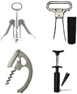
Images embodying the concepts described in the text: pull, geared pull, shear and pressure. (Image courtesy of A-Best Fixture Co., 424 West Exchange Street, Akron, Ohio 44302, USA)
3.1 Introduction and synopsis
Our aim in this chapter is to develop a strategy for selecting materials and processes that is design-led; that is, the strategy uses, as inputs, the requirements of the design. To do so we must first look briefly at design itself. This chapter introduces some of the words and phrases—the vocabulary—of design, the stages in its implementation and the ways in which materials selection links with these.
Design starts with a market need. The need is analysed, expressing it as a set of design requirements. Ways to meet these (concepts) are sought, developed (embodied) and refined (detailed) to give a product specification. The choice of material and process evolves in parallel with this process, in the way detailed in this chapter.
With this background we can develop the selection strategy. It involves four steps: translation, screening, ranking and documentation. These steps are explained and the first, that of translation, is illustrated with examples.
3.2 The design process
Original design starts from a new concept and develops the information necessary to implement it. Evolutionary design (or redesign) starts with an existing product and seeks to change it in ways that increase its performance, reduce its cost, or both.
Original design
Original design starts from scratch. It involves a new idea or working principle (the audio tape, the compact disc and the MP3 player were all, in their day, completely new). Original design can be stimulated by new materials. Thus, high-purity silicon enabled the transistor; high-purity glass, the optical fibre; high coercive-force magnets, the miniature earphone; solid-state lasers, the compact disc. Sometimes the new material suggests the new product. Sometimes instead the new product demands the development of a new material: nuclear technology drove the development of new zirconium alloys and new stainless steels; space technology stimulated the development of beryllium alloys and lightweight composites; turbine technology today drives development of high-temperature alloys and ceramics.
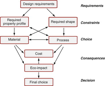
The central column of Figure 3.1 shows the design process. The starting point is a market need or a new idea; the end point is the full product specification for a product that fills the need or embodies the idea. A need must be identified before it can be met. It is essential to define the need precisely—that is, to formulate a need statement, often in the form ‘a device is required to perform task X’, expressed as a set of design requirements. Between the need statement and the product specification lie the set of stages shown in Figure 3.1: the stages of conceptual design, embodiment design and detailed design, explained in a moment.
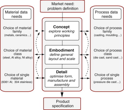
Figure 3.1 The design flow chart, showing how material and process selection enter. Information about materials is needed at each stage, but at very different levels of breadth and precision. The broken lines suggest the iterative nature of original design and the path followed in redesign.
At the conceptual design stage, all options are open: the designer considers alternative concepts and the ways in which these might be separated or combined. The next stage, embodiment, takes the promising concepts and seeks to analyse their operation at an approximate level. This involves sizing the components and a preliminary selection of materials and processes, examining the implications for performance and cost. The embodiment stage ends with a feasible layout, which becomes the input to the detailed design stage. Here specifications and dimensions for each component are drawn up. Critical components may be subjected to precise mechanical or thermal analysis. Optimisation methods are applied to components and groups of components to maximise performance, minimise cost and ensure safety. A final choice of geometry and material is made, and the methods of production are analysed and costed. The stage ends with a detailed product specification.
Redesign
Most design is not original design, in the sense of starting from a totally new idea. It is redesign, starting with an existing product and correcting its shortcomings, refining it, enhancing its performance or reducing its cost, without discarding the principles on which it operates or—frequently—many of its components.
Here are some scenarios that call for redesign. First, the most obvious, is the ‘product recall’ scenario. If a product, once released to the market, fails to meet safety standards, urgent redesign is required. Often the problem is a material failure; then an alternative must be found that retains the desirable features of the original but overcomes its weaknesses. Then there is the ‘poor value for money’ scenario: the product performs safely but offers performance that, at its price, is perceived to be mediocre, requiring redesign to enhance performance. There is, too, the ‘inadequate profit margin’ scenario in which the cost of manufacture exceeds the price that the market will bear. Much of the cost of a mass-produced product derives from the materials of which it is made and the processes chosen to make it; the response is to re-examine both, with cost-cutting as the objective. Then there is the ‘stay ahead of the competition’ scenario. Makers of household products and electronic gadgetry (electric kettles, mobile phones) release new editions annually; car manufacturers produce new models every two or three years.
In a market environment, in which many almost-identical products compete for the consumers’ attention, it is visual and stylistic character that sets some products above others. Much creative thinking goes into this ‘industrial design’ and in it the choice of material, or of a change of material, is dictated mainly by aesthetics: color, texture, feel and the ability to be shaped or finished in a given way.
Much of redesign has to do with detail—the last of the three boxes in the central window of Figure 3.1—but not all. The necessary changes may require a change of configuration and layout—the embodiment phase—or even of basic concept, replacing one of the ways of performing a function by another. So the flow chart in Figure 3.1 remains a useful summary to keep in mind. It has another use, too—as a tool (one of several) for analysing existing designs and understanding how sometimes quirky details of the final product have their origins in decisions made in the concept or embodiment stages.
Described in the abstract, these ideas are not easy to grasp. The following example will help.
Devices to open corked bottles
When you buy a bottle of wine you find, generally, that it is sealed with a cork. This creates a market need: it is the need to gain access to the wine inside. We might state it thus: ‘A device is required to allow access to wine in a corked bottle’ and might add, ‘with convenience, at modest cost, and without contaminating the wine’.
Three concepts for doing this are shown in Figure 3.2. In order, they are: to remove the cork by axial traction (= pulling); to remove it by shear tractions; to push it out from below. In the first, a screw is threaded into the cork to which an axial pull is applied; in the second, slender elastic blades inserted down the sides of the cork apply shear tractions when pulled; and in the third, the cork is pierced by a hollow needle through which a gas is pumped to push it out.
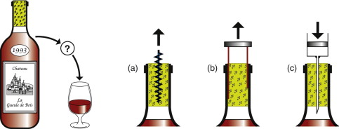
Figure 3.2 A market need—that of gaining access to wine in corked bottles—and three concepts for meeting the need. Devices based on all three of these concepts exist and can be bought.
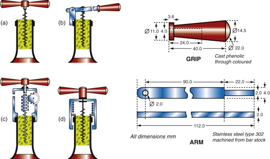
Figure 3.3 shows embodiment sketches for devices based on concept (a), that of axial traction. The first is a direct pull; the other three use some sort of mechanical advantage—levered pull, geared pull and spring-assisted pull. The embodiments suggest the layout, the mechanisms and the scale. In the final, detailed, stage of design, the components are dimensioned so that they carry the working loads safely, their precision and surface finish are defined and a final choice of material and manufacturing route is made as suggested on the right of the figure. Let us examine how this is done.
3.3 Material and process information for design
Materials selection enters each stage of the design (Figure 3.1, left-hand side). The nature of the data needed in the early stages differs greatly in its level of precision and breadth from that needed later on. At the concept stage, the designer requires only approximate property values, but for the widest possible range of materials. All options are open: a polymer may be the best choice for one concept, a metal for another. The problem, at this stage, is not precision and detail, it is breadth and speed of access: how can the vast range of data be presented to give the designer the greatest freedom in considering alternatives?
At the embodiment stage the landscape has narrowed. Here we need data for a subset of materials, but at a higher level of precision and detail. These are found in more specialized handbooks and software that deal with a single class or subclass of materials—metals, or just aluminum alloys, for instance. The risk now is that of losing sight of the bigger spread of materials to which we must return if the details don’t work out; it is easy to get trapped in a single line of thinking when others have potential to offer better solutions.
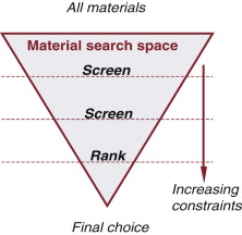
The final stage of detailed design requires a still higher level of precision and detail, but for only one or a very few materials. Such information is best found in the data sheets issued by the material producers themselves and in detailed databases for restricted material classes. A given material (polyethylene, for instance) has a range of properties that derive from differences in the ways different producers make it. At the detailed design stage, a supplier must be identified and the properties of his or her product used in the design calculations; that from another supplier may have slightly different properties. And sometimes even this is not good enough. If the component is a critical one (meaning that its failure could, in some sense or another, be disastrous), then it may be prudent to conduct in-house tests to measure the critical properties, using a sample of the material that will be used to make the product itself. The process is one of narrowing the materials search space by screening out materials that cannot meet the design requirements, ranking those that remain and identifying the most promising choice (Figure 3.4).
The materials input does not end with the establishment of production. Products fail in service and failures contain information. It is an imprudent manufacturer who does not collect and analyse data on failures. Often this points to the misuse of a material, one that redesign or reselection can eliminate.
The selection of a material cannot be separated from that of process and of shape. To make a shape, a material is subjected to processes that, collectively, we shall call manufacture. Figure 2.5 of Chapter 2 introduced them. The selection of process follows a route that runs parallel to that of material (Figure 3.1, right-hand side). The starting point is a catalog of all processes, which is then narrowed by screening out those that fail to make the desired shape or are incompatible with the choice of material. Material, shape and process interact (Figure 3.5). Process choice is influenced by the material: by its formability, machinability, weldability, heat treatability and so on. Process choice is influenced by the requirements for shape—the process determines the shape, the size, the precision and, to a large extent, the cost of a component. The interactions are two-way: specification of shape restricts the choice of material and process, but equally the specification of process limits the materials you can use and the shapes they can take. The more sophisticated the design, the tighter the specifications and the greater the interactions. The interaction between material, shape and process lies at the heart of the selection process. To tackle it we need a strategy.
3.4 The strategy: translation, screening, ranking and documentation
Selection involves seeking the best match between the attribute profiles of the materials and processes—bearing in mind that these must be mutually compatible—and those required by the design. The strategy, applied to materials, is sketched in Figure 3.6. The first task is that of translation: converting the design requirements into a prescription for selecting a material. This proceeds by identifying the constraints that the material must meet and the objectives that the design must fulfill. These become the filters: materials that meet the constraints and rank highly in their ability to fulfill the objectives are potential candidates for the design. The second task, then, is that of screening: eliminating the material that cannot meet the constraints. This is followed by the ranking step, ordering the survivors by their ability to meet a criterion of excellence, such as that of minimising cost. The final task is to explore the most promising candidates in depth, examining how they are used at present, how best to design with them, case histories of failures and a step we call documentation.
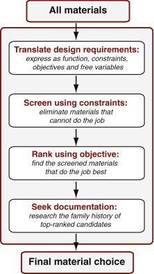
Figure 3.6 The strategy applied to materials. The same strategy is later adapted to select processes. There are four steps: translation, screening, ranking and supporting information. All can be implemented in software, allowing large populations of materials to be investigated.
Process selection follows a parallel route. In this case translation means identifying the geometric and other constraints—dimensions, shape, precision and material compatibility—that must be met, using these to screen out processes that cannot provide them. We return to process selection in Chapters 18 and 19. For now we stick to materials.
Translation
Any engineering component has one or more functions: to support a load, to contain a pressure, to transmit heat and so forth. This must be achieved subject to constraints: that certain dimensions are fixed; that the component must carry the design loads without failure, the need to insulate against or to conduct heat or electricity; that it can function in a certain range of temperature and in a given environment and many more. In designing the component, the designer has one or more objectives: to make it as cheap as possible, perhaps, or as light, or as safe, or some combination of these. Certain parameters can be adjusted in order to optimise the objective—the designer is free to vary dimensions that are not constrained by design requirements and, most importantly, free to choose the material for the component and the process to shape it. We refer to these as free variables.
Constraints, objectives and free variables (Table 3.1) define the boundary conditions for selecting a material and—in the case of load-bearing components—a shape for its cross-section.
Table 3.1 Function, constraints, objectives and free variables
| Function | •What does the component do? |
| Constraints | •What non-negotiable conditions must be met? |
| Objective | •What is to be maximised or minimised? |
| Free variables | •What parameters of the problem are the designer free to change? |
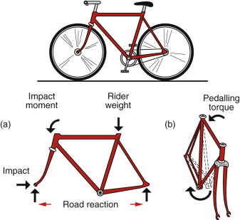
It is important to be clear about the distinction between constraints and objectives. A constraint is an essential condition that must be met, usually expressed as a limit on a material or process attribute. An objective is a quantity for which an extreme value (a maximum or minimum) is sought, frequently cost, mass or volume, but there are others (Table 3.2). Getting it right can take a little thought. In choosing materials for a super-light sprint bicycle, for example, the objective is to minimise mass, with an upper limit on cost, thus treating cost as a constraint. But in choosing materials for a cheap ‘shopping’ bike the two are reversed: now the objective is to minimise cost with a (possible) upper limit on mass, thus treating it as a constraint (Figure 3.7).
Table 3.2 Common constraints and objectives
| Common constraints | Common objectives |
|---|---|
| Meet a target value of | Minimise |
| •Stiffness | •Cost |
| •Strength | •Mass |
| •Fracture toughness | •Volume |
| •Thermal conductivity | •Impact on the environment |
| •Electrical resistivity | •Heat loss |
| •Magnetic remanence | |
| •Optical transparency | Maximise |
| •Cost | •Energy storage |
| •Mass | •Heat flow |
The outcome of the translation step is a list of the design-limiting properties and the constraints they must meet. The first step in relating design requirements to material properties is therefore a clear statement of function, constraints, objectives and free variables.
Screening
Constraints are gates: meet the constraint and you pass through the gate, fail to meet it and you are out. Screening (Figure 3.6) does just that: it eliminates candidates that cannot do the job at all because one or more of their attributes lies outside the limits set by the constraints. As examples, the requirement that ‘the component must function in boiling water’ or that ‘the component must be transparent’ imposes obvious limits on the attributes of maximum service temperature and optical transparency that successful candidates must meet. We refer to these as attribute limits.
Ranking
To rank the materials that survive the screening step we need a criterion of excellence. They are found in the material indices, developed later, and in later chapters, which measure how well a candidate that has passed the screening step can do the job (Figure 3.6 again). Performance is sometimes limited by a single property, sometimes by a combination of them. Thus, the best materials for buoyancy are those with the lowest density, ρ; those best for thermal insulation are the ones with the smallest values of the thermal conductivity, λ—provided, of course, that they also meet all other constraints imposed by the design. Here maximising or minimising a single property maximises performance. Often, though, it is not one but a group of properties that are relevant. Thus, the best materials for a light stiff tie-rod are those with the greatest value of the specific stiffness, E/ρ, where E is Young’s modulus. The best materials for a spring are those with the greatest value of ![]() , where σy is the yield strength. The property or property group that maximises performance for a given design is called its material index. There are many such indices, each associated with maximising some aspect of performance. They provide criteria of excellence that allow ranking of materials by their ability to perform well in the given application.
, where σy is the yield strength. The property or property group that maximises performance for a given design is called its material index. There are many such indices, each associated with maximising some aspect of performance. They provide criteria of excellence that allow ranking of materials by their ability to perform well in the given application.
To summarise: screening isolates candidates that are capable of doing the job; ranking identifies those among them that can do the job best.
Documentation
The outcome of the steps so far is a ranked short-list of candidates that meet the constraints and that maximise or minimise the criterion of excellence, whichever is required. You could just choose the top-ranked candidate, but what hidden weaknesses might it have? What is its reputation? Has it a good track record? To proceed further we seek a detailed profile of each: its documentation (Figure 3.6, bottom).
What form does documentation take? Typically, it is descriptive, graphical or pictorial: case studies of previous uses of the material, details of its corrosion behavior in particular environments, of its availability and pricing, warnings of its environmental impact or toxicity. Such information is found in handbooks, suppliers’ data sheets, CD-based data sources and high-quality websites. Documentation helps narrow the short-list to a final choice, allowing a definitive match to be made between design requirements and material and process attributes.
Why are all these steps necessary? Without screening and ranking, the candidate pool is enormous and the volume of documentation is overwhelming. Dipping into it, hoping to stumble on a good material, gets you nowhere. But once a small number of potential candidates have been identified by the screening–ranking steps, detailed documentation can be sought for these few alone, and the task becomes viable.
3.5 Examples of translation
The following examples illustrate the translation step for a number of problems, starting with the lever for the corkscrew of Figure 3.3, then an example of redesign.
A corkscrew lever
Figure 3.3 shows the lever for one of the corkscrews in the design case study. In use it is loaded in bending. It must carry the bending moment without deflecting to an awkward degree, it must not yield (though some cheap corkscrews do) and it must be tough enough to withstand misuse. Finally, it must not corrode in wine or water. The length of the lever is specified, but the cross-section is not—we are free to choose a section that is sufficient to bear the use-loads. Given all these, the lever should be as cheap as possible. Table 3.3 lists the translation.
Table 3.3 Translation for the corkscrew lever
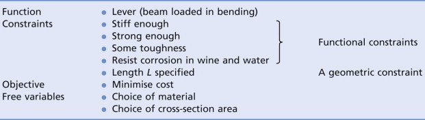
The design-limiting properties are those directly relating to the constraints: modulus E, strength σy, fracture toughness K1c and corrosion resistance.
Redesign of a CD case
Music lovers will affirm that CDs—the best of them—are divine. But the cases they come in are the work of the devil (Figure 3.8). They are—for reasons of their optical clarity—called ‘jewel’ cases, but in performance they are far from jewels. They usually are made of polystyrene (PS), chosen for its low cost and water-clear transparency, and they are made by injection moulding and that, too, is cheap if you are making millions. Polystyrene can, at least in principle, be recycled. But PS jewel cases crack easily, they jam shut, the hinges break and the corners of the case are hard and sharp enough to inflict terminal damage on a CD. So there you have it. Decide on the features you think really matter, and formulate constraints, objective and free variables for the redesign of a CD case.

The way to tackle the problem is to seek a replacement material that retains the good properties of the old one, but without the bad. Thus, we seek a material that is optically transparent to allow the label to be read, is able to be injection moulded because this is the most economic way to make large numbers, and is recyclable. But it must be tougher than polystyrene. Of the materials that meet these constraints, we want the cheapest. Table 3.4 summarises the translation.
Table 3.4 Translation for the redesigned CD case
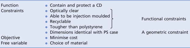
Potential design-limiting properties are optical transparency, fracture toughness, K1c (must be better than PS), and the ability to be injection moulded and recycled.
Heat sinks for microchips
A microchip may consume only milliwatts, but this power is dissipated in a tiny volume, making the power density high. As chips shrink and clock speeds grow, overheating becomes a problem. The chip in your PC already reaches 85 °C, requiring forced cooling. Multiple-chip modules (MCMs) pack as many as 130 chips on to a single substrate, and they get even hotter—up to 180 °C. Heating is kept under control by attaching the chips to a heat sink (Figure 3.9), taking pains to ensure good thermal contact between chip and sink. The heat sink now becomes a critical component, limiting further development of the electronics. How can its performance be maximised?
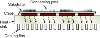
To prevent electrical coupling and stray capacitance between chip and heat sink, the heat sink must be a good electrical insulator. If it is to work with one surface at 180 °C, it must have a maximum service temperature (the temperature at which it can operate continuously without damage) that is at least as great as 180 °C. These define the constraints. To drain heat away from the chip as fast as possible, it must also have the highest possible thermal conductivity, λ, defining the objective. The translation step is summarised in Table 3.5, where we assume that all dimensions are constrained by other aspects of the design.
Table 3.5 Translation for the heat sink
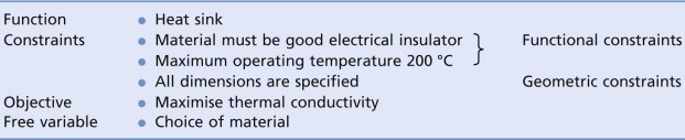
The design-limiting properties, clearly, are maximum service temperature Tmax, electrical resistivity ρe and thermal conductivity λ.
HF transformer cores
An electrical transformer uses electromagnetic induction to convert one AC voltage to another (Figure 3.10). To minimise energy loss the material must be a soft magnet—one that is easy to magnetise and demagnetise (Chapter 15). And to avoid eddy current losses at high frequencies it must also be an electrical insulator. The constraints of ‘soft magnetic material’ and ‘electrical insulator’ are very restrictive—they will screen out all but a small number of candidates. If the transformer is for an everyday product, the objective would be to minimise the cost. Table 3.6 lists the translation.
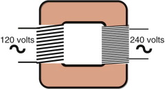
Figure 3.10 A transformer. The core must be a soft magnetic material, and if this is a high-frequency transformer, it must be an electrical insulator.
Table 3.6 Translation for the transformer core
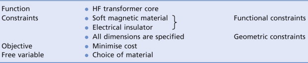
|
These translations are the first step in selection. In them we have identified the constraints; they will be used for screening. We also have identified the objective; it will be used for ranking. We will return to all four of these examples in later chapters when we know how to screen and rank.
3.6 Summary and conclusions
The starting point of a design is a market need captured in a set of design requirements. Concepts for a product that meet the need are devised. If initial estimates and exploration of alternatives suggest that the concept is viable, the design proceeds to the embodiment stage: working principles are selected, size and layout are decided, and initial estimates of performance and cost are made. If the outcome is successful, the designer proceeds to the detailed design stage: optimisation of performance, full analysis of critical components, preparation of detailed production drawings (usually as a CAD file), showing dimensions, specifying precision and identifying material and manufacturing paths. But design is not a linear process, as Figure 3.1 might suggest. Some routes lead to a dead end, requiring reiteration of earlier steps. And, frequently, the task is one of redesign, requiring that constraints be rethought and objectives realigned.
The selection of material and process runs parallel to this set of stages. Initially the search space for both is wide, encompassing all possible candidates. As the design requirements are formulated in increasing detail, constraints emerge that both must meet, and one or more objectives is formulated. The constraints narrow the search space and the objective(s) allows ranking of those that remain. Identifying the constraints, the objectives and free variables (the process we called ‘translation’) is the first step in selection. This chapter ended with examples of translation when the task was that of choosing a material; the exercises suggest more. When the task is the choice of process, a similar translation is needed; we return to this in Chapter 18. The other steps—screening, ranking and documentation—are discussed in chapters that follow.
Ashby M.F. Materials Selection in Mechanical Design 3rd ed. 2005 Butterworth-Heinemann Oxford, UK Chapter 4. ISBN 0-7506-6168-2. (A more advanced text that develops the ideas presented here in greater depth.)
Cross N. Engineering Design Methods 3rd ed. 2000 Wiley Chichester, UK ISBN 0-471-87250-3. (A durable text describing the design process, with emphasis on developing and evaluating alternative solutions.)
French M.J. Conceptual Design for Engineers 1985 The Design Council London, UK and Springer, Berlin, Germany. ISBN 0-85072-155-5 and 3-540-15175-3. (The origin of the Concept—Embodiment—Detail block diagram of the design process. The book focuses on the concept stage, demonstrating how simple physical principles guide the development of solutions to design problems.)
Pahl G., Beitz W. Engineering design 2nd ed. 1997 The Design Council London, UK translated by K. Wallace and L. Blessing, and Springer, Berlin, Germany. ISBN 0-85072-124-5 and 3-540-13601-0. (The Bible—or perhaps more exactly the Old Testament—of the technical design field, developing formal methods in the rigorous German tradition.)
Ullman D.G. The Mechanical Design Process 3rd ed. 2003 McGraw-Hill New York, USA ISBN 0-07-112281-8. (An American view of design, developing ways in which an initially ill-defined problem is tackled in a series of steps, much in the way suggested by Figure 3.1 of the present text.)
Ulrich K.T., Eppinger S.D. Product Design and Development 1995 McGraw-Hill New York, USA ISBN 0-07-065811-0. (A readable, comprehensible text on product design, as taught at MIT. Many helpful examples but almost no mention of materials.)
3.8 Exercises
- Exercise E3.1 What are the steps in developing an original design?
- Exercise E3.2 Describe and illustrate the ‘translation’ step of the material selection strategy.
- Exercise E3.3 What is meant by an objective and what by a constraint in the requirements for a design? How do they differ?
- Exercise E3.4 You are asked to design a fuel-saving cooking pan with the goal of wasting as little heat as possible while cooking. What objective would you choose, and what constraints would you think must be met?
- Exercise E3.5 Bikes come in many forms, each aimed at a particular sector of the market:
Use your judgement to identify the primary objective and the constraints that must be met for each of these.
- Exercise E3.6 A material is required for the windings of an electric air-furnace capable of temperatures up to 1000 °C. Think out what attributes a material must have if it is to be made into windings and function properly in a furnace. List the function and the constraints; set the objective to ‘minimise material price’ and the free variable to ‘choice of material’.
- Exercise E3.7 A material is required to manufacture office scissors. Paper is an abrasive material and scissors sometimes encounter hard obstacles like staples. List function and constraints; set the objective to ‘minimise material price’ and the free variable to ‘choice of material’.
- Exercise E3.8 A material is required for a heat exchanger to extract heat from geo-thermally heated, saline, water at 120 °C (and thus under pressure). List function and constraints; set the objective to ‘minimise material price’ and the free variable to ‘choice of material’.
- Exercise E3.9 A material is required for a disposable fork for a fast-food chain. List the objective and the constraints that you would see as important in this application.
- Exercise E3.10 Formulate the constraints and objective you would associate with the choice of material to make the forks of a racing bicycle.
- Exercise E3.11 Cheap coat-hangers used to be made of wood—now it is only expensive ones that use this material. Most coat-hangers are now metal or plastic, and both differ in shape from the wooden ones, and from each other. Examine wood, metal and plastic coat-hangers, comparing the designs, and comment on the ways in which the choice of material has influenced them.
- Exercise E3.12 Cyclists carry water in bottles that slot into bottle holders on their bicycles. Examine metal and plastic bottle holders, comparing the designs, and comment on the ways in which the choice of material has influenced them.
3.9 Exploring design using CES
The ‘Search’ facility of CES allows a full-text search of all records, identifying those that contain the search string. The default setting applies the search to the Materials universe only. The pull-down menu headed ‘Look in table:’ allows this to be reset to the Process universe or to All tables.
- Exercise E3.13 A company wishes to enhance its image by replacing oil-based plastics in its products by polymers based on natural materials. Use the ‘Search’ facility in CES to find Biopolymer. List the materials you find.
- Exercise E3.14 A maker of garden furniture is concerned that the competition is stealing part of his market with furniture made by RTM, a term with which he is unfamiliar. Use the ‘Search’ facility in CES to find out what RTM is, and whether it is used to make things like garden furniture. (Remember that it is the Process universe that must be searched, since this is a process.)
- Exercise E3.15 Use the ‘Search’ facility in CES to find materials for furnace windings.
- Exercise E3.16 Use the ‘Search’ facility in CES to find materials for scissors and knife blades.
- Exercise E3.17 Use the ‘Search’ facility in CES to find materials for heat exchangers.
- Exercise E3.18 Use the ‘Search’ facility in CES to find materials for flooring.