
Chapter 11 Rub, slither and seize: Friction and wear
- 11.1 Introduction and synopsis 228
- 11.2 Tribological properties 228
- 11.3 Charting friction and wear 230
- 11.4 The physics of friction and wear 232
- 11.5 Design and selection: materials to manage friction and wear 234
- 11.6 Summary and conclusions 239
- 11.7 Further reading 240
- 11.8 Exercises 240
- 11.9 Exploring design with CES 241
God, it is said, created materials, but their surfaces are the work of the devil. They are certainly the source of many problems. When surfaces touch and slide, there is friction; and where there is friction, there is wear. Tribologists—the collective noun for those who study friction and wear—are fond of citing the enormous cost, through lost energy and worn equipment, for which these two phenomena are responsible. It is certainly true that, if friction could be eliminated, the efficiency of engines, gearboxes, drive trains and the like would increase enormously; and if wear could be eradicated, they would also last much longer. But before accepting this negative image, we should remember that, without wear, pencils would not write on paper or chalk on blackboards; and without friction, we would slither off the slightest incline.
11.1 Introduction and synopsis
God, it is said, created materials, but their surfaces are the work of the devil. They are certainly the source of many problems. When surfaces touch and slide, there is friction; and where there is friction, there is wear. Tribologists—the collective noun for those who study friction and wear—are fond of citing the enormous cost, through lost energy and worn equipment, for which these two phenomena are responsible. It is certainly true that, if friction could be eliminated, the efficiency of engines, gearboxes, drive trains and the like would increase enormously; and if wear could be eradicated, they would also last much longer. But before accepting this negative image, we should remember that, without wear, pencils would not write on paper or chalk on blackboards; and without friction, we would slither off the slightest incline.
Tribological properties are not attributes of one material alone, but of one material sliding on another with—almost always—a third in between. The number of combinations is far too great to allow choice in a simple, systematic way. The selection of materials for bearings, drives and sliding seals relies heavily on experience. This experience is captured in reference sources (for which, see ‘Further reading’); in the end it is these that must be consulted. But it does help to have a feel for the magnitude of friction coefficients and wear rates, and an idea of how these relate to material class. This chapter provides it.
11.2 Tribological properties
When two surfaces are placed in contact under a normal load Fn and one is made to slide over the other, a force Fs opposes the motion. This force Fs is proportional to Fn but does not depend on the area of the surface, facts discovered by none other than Leonardo da Vinci1, then forgotten, then rediscovered 200 years later by Amontons2, whose name they carry. The coefficient of friction µ is defined as in Figure 11.1:
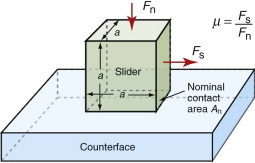
Figure 11.1 The definition of the coefficient of friction, µ. Here Fn is the force normal to the interface and Fs the force parallel to the interface required to maintain sliding.

When surfaces slide, they wear. Material is lost from both surfaces, even when one is much harder than the other. The wear rate, W, is conventionally defined as
and thus has units of m2. A more useful quantity, for our purposes, is the wear rate per unit area of surface, called the specific wear rate, Ω:

which is dimensionless. It increases with bearing pressure P (the normal force Fn divided by An), such that
where ka, the Archard wear constant, has units of (MPa)−1. It is a measure of the propensity of a sliding couple for wear: high ka means rapid wear at a given bearing pressure.
Example 11.2
A dry sliding bearing oscillates with an amplitude of a = 2 mm at a frequency f = 1 Hz under a normal load of Fn = 10 N. The nominal area of the contact is An = 100 mm2. The Archard wear constant for the materials of the bearing is ka = 10−8 MPa−1 = 10−8. If the bearing is used continuously for one year, how much will the surfaces have worn down?
Answer. Define Δx as the distance the surfaces have worn down. Then

The distance slid per cycle is 4a. One year is t = 3.15 × 10⁷ s. The distance slid is 4a ft = 2.5 × 10⁵ m giving a wear Δx = 2.5 × 10⁻⁴ m = 0.25 mm.
11.3 Charting friction and wear
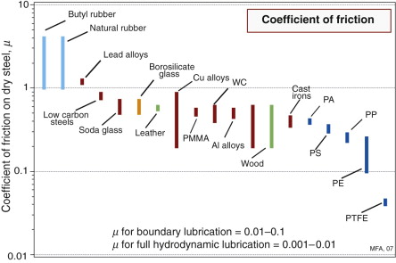
The coefficient of friction
Approximate values for the coefficient of friction for dry—that is, unlubricated—sliding of materials on a steel counterface are shown in Figure 11.2. The values depend on the counterface material, but the range is much the same: typically, µ ≈ 0.5. Certain combinations show much higher values, either because they seize when rubbed together (a soft metal rubbed on itself in a vacuum with no lubrication, for instance) or because one surface has a sufficiently low modulus that it conforms to the rough surface of the other (rubber on rough concrete). At the other extreme are sliding combinations with exceptionally low coefficients of friction, such as PTFE, or bronze bearings loaded with graphite, sliding on polished steel. Here the coefficient of friction falls as low as 0.04, though this is still high compared with friction for lubricated surfaces, as noted at the bottom of the diagram.
The wear rate–hardness chart
Figure 11.3 shows the Archard wear constant ka plotted against hardness, here expressed in MPa. (Hardness in MPa ≈ 10 × Vickers hardness, HV.) The bearing pressure P is the quantity specified by the design. The ability of a surface to resist a static contact pressure is measured by its hardness, so the maximum bearing pressure Pmax is just the hardness H of the softer surface. Thus, the wear rate of a bearing surface can be written:
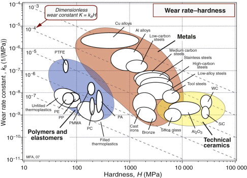
Figure 11.3 The normalised wear rate for lubricated sliding, ka plotted against hardness H, here expressed in MPa rather than Vickers (H in MPa = 10 Hv). The chart gives an overview of the way in which common engineering materials behave.
Two material properties appear in this equation: the wear constant ka and the hardness, H—they are the axes of the chart. The diagonal contours show the product
The best materials for bearings for a given bearing pressure P are those with the lowest value of ka—that is, those nearest the bottom of the diagram. On the other hand, an efficient bearing, in terms of size or weight, will be loaded to a safe fraction of its maximum bearing pressure—that is, to a constant value of P/Pmax—and for these, materials with the lowest values of the product kaH are best. Materials of a given class (metals, for instance) tend to lie along a downward sloping diagonal across the figure, reflecting the fact that low wear rate is associated with high hardness.
Example 11.3
A newly developed polymer composite hardened with nano-scale ceramic particles is found to have a hardness of 100 Vickers. Extrapolate the data for polymers on the Chart of Figure 11.3 to estimate approximately the Archard wear constant you might expect it to have.
Answer. A hardness of 100 Vickers = 1000 MPa. An extrapolation of the metals data to 1000 MPa gives an Archard wear constant of about 10−10 MPa−1.
11.4 The physics of friction and wear3
Friction
Surfaces, no matter how meticulously honed and polished, are never perfectly flat. The roughness, defined in Chapter 18, depends on how the surface was made—a sand-casting has a very rough surface, one that is precision-machined has a much smoother one. But none—none—are perfectly smooth. Magnified vertically, they look like Figure 11.4(a)—an endless range of asperity peaks and troughs. Thus, when two surfaces are placed in contact, no matter how carefully they have been crafted, they touch only at points where asperities meet as in Figure 11.4(b). The load Fn is supported solely by the contacting asperities. The real contact area Ar is only a tiny fraction of the apparent, nominal, area An.
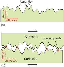
Figure 11.4 (a) The profile of a surface, much magnified vertically. (b) Two surfaces in contact touch only at asperities.
What is this fraction? When they first touch the asperities deform elastically. But even small loads cause large contact stresses, enough to cause plastic deformation as in Figure 11.5(a). The contact points flatten, forming junctions with a total area Ar, as in Figure 11.5(b). The total load transmitted across the surface is
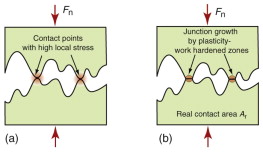
Figure 11.5 When surfaces first touch, high contact stresses appear, as in (a). These cause plasticity and junction growth until the junction area Ar can just support the load Fn without further plasticity, as in (b).
where σy is the yield strength. Thus, the real contact area is

To see how small this is, return to the cube of Figure 11.1. Its mass is m = ρa3, so the force needed to support it is Fn = ρga3 = ρgaAn = Arσy, where An = a2 is the nominal contact area and g is the acceleration due to gravity (9.81 m/s2). Thus, the ratio of real to nominal contact areas is

Thus, a 100 mm cube of ordinary steel (density 7900 kg/m3, yield strength 200 MPa), weighing a hefty 7.9 kg, contacts any hard surface on which it rests over only 0.4 mm2.
Now think of sliding one surface over the other. If the junctions weld together (as they do when surfaces are clean), it will need a shear stress Fs equal to the shear yield strength k of the material to shear them or, if the materials differ, one that is equal to the shear strength of the softer material. Thus, for unlubricated sliding

or, since k ≈ σy/2,
Dividing this by equation (11.6) gives
a value right in the middle of the spread in Figure 11.2.
So far we have spoken of sliding friction—Fs is the force to maintain a steady rate of sliding. If surfaces are left in static contact, the junctions tend to grow by creep, and the bonding between them becomes stronger so that the force to start sliding is larger than that to maintain it. This means that the coefficient of friction to start sliding, called the static coefficient, µs, is larger than that to sustain it, resulting in stick-slip behavior that can cause vibration in brakes, and is the way that the bow-hair causes a violin string to resonate.
Wear
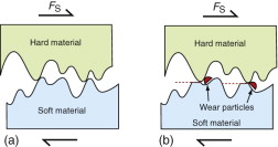
We distinguish two sorts of sliding wear. In adhesive wear, characteristic of wear between the same or similar materials (copper on aluminum, for example), asperity tips, stuck together, shear off to give wear damage. In abrasive wear, characteristic of wear when one surface is much harder than the other (steel on plastic, say), the asperity tips of the harder material plough through the softer one, abrading it like sandpaper.
Figure 11.6 shows the way in which adhesion between surfaces causes wear fragments to be torn from the surface. To minimise the rate of wear we need to minimise the size of the fragments; that means minimising the area of contact. Since Ar = Fn/σy, reducing the load or increasing σy (that is, the surface hardness) reduces wear.
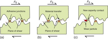
Figure 11.6 Adhesive wear: adhesion at the work-hardened junctions causes shear-off of material when the surfaces slide.
Figure 11.7 shows abrasive wear. The asperities of the harder surface slice off segments of the softer one, like grating cheese. More commonly the problem is one of contamination: hard particles that sneak into the surface—dust, sand, oxidised wear particles—embed themselves in one surface and plough through the other. It is to prevent this that cars have air and oil filters.
11.5 Design and selection: materials to manage friction and wear
Bearings allow two components to move relative to each other in one or two dimensions while constraining them in the others. The key criteria are low friction coupled with the ability to support the bearing load Fn without yielding, overheating or wearing excessively. Brakes and clutches, by contrast, rely on high friction, but there is more to their design than that, as we shall see in a moment. But first, bearings.
Dry sliding, as we have seen, generally leads to friction with a coefficient µ of about 0.5. If the bearings of the drive-train of your car had a µ of this magnitude, negligible power would reach the wheels—almost all would be lost as heat in the bearing surfaces. In reality, about 15% of the power of the engine is lost in friction because of two innovations: lubrication and the replacement of sliding by rolling bearings.
Lubrication
Most lubricants are viscous oils containing additives with polar groups (fatty acids with −OH− groups not unlike ordinary soap) that bind to metal surfaces to create a chemisorbed boundary layer (Figure 11.8). A layer of the lubricant between the surfaces allows easy shear, impeded only by the viscosity of the oil, giving a coefficient of fraction in the range 0.001–0.01. When the sliding surfaces are static, the bearing load Fn tends to squeeze the oil out of the bearing, but the bonding of the additive is strong enough to resist, leaving the two surfaces separated by a double-layer of lubricating molecules. This boundary-layer lubrication is sufficient to protect the surfaces during start-up and sliding at low loads, but it is not something to rely on for continuous use or high performance. For this you need hydrodynamic lubrication.
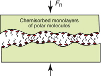
Figure 11.8 The formation of a boundary layer of chemisorbed, polar molecules; the red dot represents the polar group, the tail the hydrocarbon chain attached to it.
The viscosity of the oil is both a curse and a blessing—a curse because it exerts a drag (and thus friction) on the sliding components; a blessing because, without it, hydrodynamic lubrication would not be possible. Figure 11.9 explains this (an explanation first provided by Reynolds4). Sliding bearings are designed so that the surfaces are slightly inclined. Oil is dragged along the wedge-shaped region between them from the wide to the narrow end, as in Figure 11.9(a). The rise in pressure as the oil is compressed forces the surfaces apart against the force of the normal load carried by the bearing. The maximum pressure is reached just behind the centre of the slider, where the color is most intense in the figure. The same principle governs the self-alignment of a rotating journal bearing, as in Figure 11.9(b). Again, the lubricant is dragged by viscosity into the wide end of the wedge-shaped region and swept toward the narrow end, where the rise of pressure pushes the journal back onto the axis of the bearing. The result is that the surfaces never touch but remain separated by a thin film of oil or other lubricating fluid.
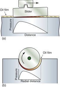
Figure 11.9 The distribution of pressure under a sliding and a rotating bearing with hydrodynamic lubrication.
At high temperatures, hydrocarbon lubricants decompose. Solid lubricants—PTFE, molybdenum disulfide (MoS2) and graphite (one form of carbon)—extend the operating temperature to 500 °C. PTFE, good to about 250 °C, has an intrinsically low coefficient of friction. Moly-disulfide (up to 300 °C) and graphite (to 500 °C) rely on their lamellar (layer-like) crystal structure, able to shear easily on certain crystal planes, to provide coefficients of friction well below 0.1. All these can be applied as lubricants or incorporated into the pores of porous bearings (made by sintering powdered metal like bronze and cast iron) to give self-lubricating bearings.
That’s the background. So what materials are good for bearings? That depends—plane bearings or roller bearings?
Plane bearings
The surfaces of sliding bearings, if properly lubricated, do not touch. Then almost any material that meets the other constraints of the design will do—steel, cast iron, brass, bronze. The key material properties are strength (to carry the bearing loads), corrosion resistance and conformability—the ability to adapt to slight misalignment. Full hydrodynamic lubrication breaks down under static loads or when sliding velocities are small, and long-term reliance on boundary lubrication is risky. Bearing materials are designed to cope with this.
When soft metals slide over each other (lead on lead, for instance), the junctions are weak but their area of contact is large so µ is large. When hard metals slide (e.g., steel on steel), the junctions are small but they are strong, and again µ is large. The way to get low friction with high strength is to support a soft metal with a hard one, giving weak junctions of small area. White-metal bearings, for example, consist of soft lead or tin supported in a matrix of a stronger material; leaded-bronze bearings consist of a matrix of strong, corrosion-resistant bronze containing particles of soft lead that smear out to give an easily sheared surface film when asperities touch; polymer-impregnated porous bearings are made by partly sintering bronze and then forcing a polymer (usually PTFE) into its pores. Bearings like these are not designed to run dry, but if they do, the soft component saves them, at least for a while.
Rolling bearings
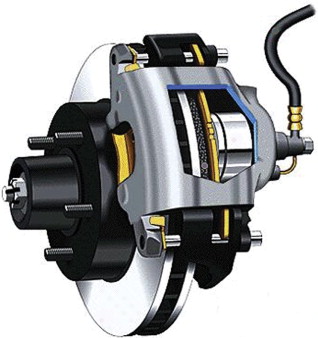
In rolling element bearings the load is carried by a set of balls or rollers trapped between an inner and an outer race by a cage, as in Figure 11.10. When the loading is radial the load is carried at any instant by half the balls or rollers, but not equally: the most heavily loaded one carries about 5/Z times the applied load, where Z is the total number of balls or rollers in the bearing. Its contact area with the race is small, so the contact stresses are high.
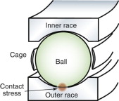
Figure 11.10 A rolling-contact bearing. The contact stresses are high, requiring materials with high hardness and resistance to fatigue failure.
The main requirement is that the deformation of the components of the bearing remain at all times elastic, so the criterion for material choice is that of high hardness. That usually means a high-carbon steel or a tool steel. If the environment is corrosive or the temperature high, stainless steel or ceramic (silicon carbide or silicon nitride) is used. When the loads are very light the races can be made from thermoplastic—polypropylene or acetal—with the advantage that no lubrication is needed (cheap bike pedals sometimes have such bearings).
When rolling element bearings fail, it is usually because of fatigue—the repeated loading and unloading of ball and race as the bearing rotates causes cracks to nucleate, splitting the balls or pitting the races. Inclusions in the material are sources of fatigue cracks, so steels for rolling bearings are processed to be as clean and inclusion free as possible by processing under vacuum.
High friction: materials for brakes and clutches
Applying friction sounds easy—just rub. Brakes for horse-drawn carriages did just that—spoon-shaped blocks of wood, sometimes faced with leather (bigger µ), were wound down with a screw to rub on the rim of the carriage wheel. But brake materials today do much more.
The friction coefficient of materials for brake linings is—surprisingly—not special: µ is about 0.4. The key thing is not µ but the ability to apply it without vibration, wear or fade. That is not easy when you reckon that, to stop a one-tonne car from 100 kph (60 mph) requires that you find somewhere to put about 0.4 MJ. That’s enough (if you don’t lose any) to heat 1 kg of steel to 800 °C. Brake materials must apply friction at temperatures that can approach such values, and they must do so consistently and without the stick-slip that causes ‘brake squeal’—not acceptable in even the cheapest car. That means materials that can tolerate heat, conduct it away to limit temperature rise and—curiously—lubricate, since it is this that quenches squeal.
For most of the history of the automobile, brake linings were made of compacted asbestos (able to tolerate 2000 °C) mixed with brass or copper particles or wires for heat conduction and strength. When it became apparent that asbestos dust—the product of brake wear—was perhaps not so good for you, new materials appeared. They are an example of hybrid material design methods: no one material can do what you want, so we synthesise one that does.
Today’s materials are a synthesis: a matrix, an abrasive additive to increase friction, a reinforcement—one to help conduct heat if possible—and a lubricant to suppress vibration. Intimate details are trade secrets, but here is the idea. The brake pads on your bike are made up of a synthetic rubber with particles of a cheap silicate to reduce pad wear and give wet friction. Those on your car have a phenolic matrix with particles of silicates, silicon carbide (sandpaper grit) to control friction and graphite or MoS2 as a lubricant. Those on a military jet, a 747 or an F1 car are carbon or ceramic—here high temperature is the problem; replacement every 10 days is acceptable if they stand the heat (try calculating how much aluminum you could melt with the energy dissipated in bringing a 200-tonne 747 to rest from 200 kph).
Waging war on wear
As explained earlier, the rate of wear increases with the bearing pressure P (equation (11.4)). It also increases with sliding velocity v because the faster the sliding, the more work is done against friction and it all turns into heat. A given bearing material has an acceptable P–v envelope within which it is usable; venture outside it and seizure or catastrophic wear awaits you (Figure 11.11(a)). To extend the envelope upward, we select materials with higher strength; to extend it laterally, we choose materials with higher thermal conductivity and melting point—or lower friction.
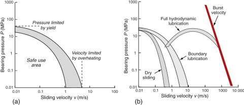
Figure 11.11 (a) A P–v curve for a bearing material. (b) P–v envelopes for various lubricated and unlubricated sliding, ultimately limited by the disintegration of the bearing under centrifugal force at very high velocities.
Lubrication, of course, reduces friction. Figure 11.11(b) shows that this does not increase the admissible bearing pressure—that is a static property of the material—but it does increase the permissible sliding velocity. Boundary lubrication expands the envelope a little; hydrodynamic lubrication expands it much more—but note its drop-off at low velocities because there is not enough sliding speed to build up the pressure profiles of Figure 11.9.
At very high rotational velocities, approached in ultra-centrifuges, gyroscopic navigation systems and super-flywheels for energy storage, there is an ultimate cut-off. It is the speed at which centrifugal forces exceed the strength of the material and the whole system disintegrates.
Hard materials have low wear rates but they tend to be brittle. Soft ones are tougher but they wear rapidly. Wear is a surface property, toughness a property of the bulk. So the way to fight wear is to take a tough material and give it a hard surface coating, using techniques of surface treatment. High-carbon steels are surface hardened by rapidly heating with a flame, an electron beam or a laser beam and then quenching the surface. Carburising, nitriding and boriding give wear resistance to components like crankshafts or ball races by diffusing carbon, nitrogen or boron atoms into a thin surface layer, where they react to give particles of carbides, nitrides or borides. Hard, corrosion-resistant layers of alloys rich in tungsten, cobalt or chromium can be sprayed onto surfaces, but a refinishing process is then necessary to restore dimensional precision. Hard ceramic coatings of alumina (Al2O3) or of tungsten or titanium carbide (WC, TiC) can be applied by plasma spraying to give both wear resistance and resistance to chemical attack, and chemical and physical vapour deposition methods allow surface coatings of other metals and ceramics, including diamond-like carbon.
Records for all these treatments (and more) are contained in the CES software under the heading ‘Surface treatment’. The software allows selection of coatings to meet given design requirements, of which wear resistance is one of the more important. We return to these in Chapter 18 on selecting processes.
11.6 Summary and conclusions
When surfaces slide, there is friction and there is wear. Eliminate all friction and a spinning wheel would spin forever. Eliminate all wear and it would last forever too. Both are about as probable as living forever while eating nothing. So we have to learn to live with friction and wear: to use them when they are useful, to minimise the problems they cause when they are a nuisance.
The remarkable thing about friction is that, if you slide one surface over another, the force to do so depends only on the normal force pushing the surfaces together, not on the area of the surface. That is because surfaces are not perfectly smooth; they touch only at points (flattened a little by the pressure)—just enough of them to support the normal force. Changing the area does not change the number of contact points. The sliding force is the force to shear the contact points, so it, too, is independent of area.
The points of contact are where wear happens. When surfaces slide the points shear off, becoming wear particles. This process can be useful—it helps surfaces bed down and conform by what is called ‘run-in’. But if the wear particles or particles from elsewhere (dust, grit) get between the surfaces, the grinding action continues and the surfaces wear.
Soft materials—lead, polyethylene, PTFE, graphite—shear easily. Impregnating a sliding material with one of these reduces friction—skis and snow boards have polyethylene surfaces for just this reason. Better still is hydrodynamic lubrication: floating the sliding surfaces apart by dragging fluid between them. Flotation requires that the surfaces slide; if they stop the fluid is squeezed out. Clever lubricants overcome this by bonding to the surfaces, leaving a thin boundary layer that is enough to separate the surfaces until hydrodynamic lubrication gets going.
Friction, wear and corrosion cause more damage to mechanisms than anything else. They are the ultimate determinants of the life of products—or they would be, if we kept them until they wore out. But in today’s society, many products are binned before they are worn out; many when they still work perfectly well. More on that subject in Chapter 20.
Bowden F.P., Tabor D. The Friction and Lubrication of Solids Parts 1 and 2 1950, 1964 Oxford, University Press Oxford, UK ISBN 0-19-851204-X. (Two volumes that establish the cornerstones of tribology: contact between solids; friction of metals and non-metals; frictional temperature rise; boundary lubrication and other chemical effects; adhesion; sliding wear; and hardness.)
Hutchings I.M. Tribology: Friction and Wear of Engineering Materials 1992 Arnold London, UK ISBN 0-340-56184-X. (An introduction to the mechanics and materials science of friction, wear and lubrication.)
Neale M.J. The Tribology Handbook 2nd ed. 1995 Butterworth-Heinemann Oxford, UK ISBN 0-7506-1198-7. (A tribological bible: materials, bearings, drives, brakes, seals, lubrication failure and repair.)
11.8 Exercises
- Exercise E11.1 Define the coefficient of friction. Explain why it is independent of the area of contact of the sliding surfaces.
- Exercise E11.2 Woods—both resinous wood from the pine family and hardwoods like Lignum vitae (it is so dense it sinks in water)—were, historically, used for bearings; even clocks had hardwood bearings. Why? Think of your own ideas, then research the Web.
- Exercise E11.3 Give examples, based on your experience in sport (tennis, golf, swimming, skiing, rock climbing, hang-gliding, etc.) of instances in which friction is wanted and when it is not.
- Exercise E11.4 Now a more challenging one. Do the same, based again on your experience in sport, of instances in which wear is desirable and in which it is not.
- Exercise E11.5 What are the characteristics of materials that are a good choice for use as brake pads?
- Exercise E11.6 A 30 mm diameter plane bearing of length 20 mm is to be made of a material with the P–v characteristics shown in Figure 11.11(b). If the bearing load is 300 N and the maximum rotation rate is 500 rpm, is it safe to run it dry? If not, is boundary lubrication sufficient? (Remember that the bearing pressure is the load divided by the projected area normal to the load.)
- Exercise E11.7 A bronze statue weighing 4 tonnes with a base of area 0.8 m2 is placed on a granite museum floor. The yield strength of the bronze is 240 MPa. What is the true area of contact, Ar, between the base and the floor?
- Exercise E11.8 The statue of the previous example was moved to a roof courtyard with a lead floor. The yield strength of the lead is 6 MPa. What now is the true area of contact?
- Exercise E11.9 How would you measure the true area of contact Ar between two surfaces pressed into contact? Use your imagination to devise ways.
11.9 Exploring design with CES (use Level 2 unless otherwise stated)
- Exercise E11.10 Use the ‘Search’ facility to find materials that are used as ball bearings. (Search on the singular—ball bearing—since that picks up the plural as well.)
- Exercise E11.11 Use the ‘Search’ facility to find materials that are used for brake pads. Do the same for brake discs.
- Exercise E11.12 Use a ‘Limit’ selection stage applied to the Surface Treatment data table to find processes that enhance wear resistance. (To do this, click ‘Select’ in the main toolbar, then ‘Selection Data’, just below it. Select Level 2 Surface treatment in the dialog box. Open a ‘Limit’ stage, open Function of treatment, and click Wear resistance.) Explore the record for laser-based methods. What are its typical uses?
- Exercise E11.13 Follow the same procedure as that of the previous example to search for processes used to control friction. Explore the record for grinding and mechanical polishing. What are grinding wheels made of?
1Leonardo da Vinci (1452–1519), Renaissance painter, architect, engineer, mathematician, philosopher and prolific inventor.
2Guillaume Amontons (1663–1705), French scientific instrument maker and physicist, perfector of the clepsydra or water clock—a device for measuring time by letting water flow from a container through a tiny hole.
3We owe our understanding of friction and wear to the work of many engineers and scientists, above all to the remarkably durable and productive collaboration between the Australian Philip Bowden (1903–1968) and David Tabor (1913–2005), English of Lithuanian descent, between 1936 and 1968 in Melbourne and Cambridge.
4Osborne Reynolds (1842–1912), Northern Irishman, brilliant mathematician and engineer but awful lecturer, known for his contributions to lubrication, turbulence and for his celebrated Number—the dimensionless group describing the transition from laminar to turbulent flow.