
4
INPUT AND OUTPUT DEVICES
Contents
- Input-output unit—Input unit, output unit
- Input devices—Human data entry devices, source data entry devices
- Human data entry devices
- Keyboard
- Pointing devices—Mouse, trackball, joystick, digitizing tablet
- Pick devices—Light pen, touch screen
- Source data entry devices
- Audio input device (microphone, sound card, speech recognition)
- Video input device (video camera, digital camera)
- Optical input devices—Scanner (hand held, flat bed), OCR, MICR, OMR, barcode reader
- Output devices—Hard copy devices, soft copy devices
- Hard copy devices
- Printer—Impact printers (dot matrix, daisy wheel, drum), non-impact printers (ink-jet, laser)
- Plotter—Drum plotter, flatbed plotter
- Computer output on microfilm (microfiche)
- Soft copy devices—Monitor, visual display terminal, video output, audio response (speakers, headphone)
- I/O port—Parallel port, serial port, USB port, firewire port
- Working of I/O system—I/O devices, device controller, device driver
Why this chapter
What is the use of the computer for us? We may want to process data, write project reports, listen to sound recordings, watch a movie and do many more things. But to do any of these things, we should be able to provide the data to the computer and also get the output from it. The input devices and output devices are used this purpose. The aim of this chapter is to introduce the different kinds of input and output devices.
4.1 INTRODUCTION
A computer interacts with the external environment via the input-output (I/O) devices attached to it. Input device is used for providing data and instructions to the computer. After processing the input data, computer provides output to the user via the output device. The I/O devices that are attached, externally, to the computer machine are also called peripheral devices. Different kinds of input and output devices are used for different kinds of input and output requirements. In this chapter, we shall discuss different kinds of input devices and output devices.
4.2 INPUT-OUTPUT UNIT
An I/O unit is a component of computer. The I/O unit is composed of two parts—input unit and output unit. The input unit is responsible for providing input to the computer and the output unit is for receiving output from the computer.
4.2.1 Input Unit
- The input unit gets the data and programs from various input devices and makes them available for processing to other units of the computer.
- The input data is provided through input devices, such as—keyboard, mouse, trackball and joystick. Input data can also be provided by scanning images, voice recording, video recording, etc.
- Irrespective of the kind of input data provided to a computer, all input devices must translate the input data into a form that is understandable by the computer, i.e., in machine readable form. The transformation of the input data to machine readable form is done by the input interface of input device.
In brief, the input unit accepts input data from the user via input device, transforms the input data in computer acceptable form using input interface for the input device and provides the transformed input data for processing.
4.2.2 Output Unit
- The output unit gets the processed data from the computer and sends it to output devices to make them available to the user of computer.
- The output data is provided through output devices like display screen, printer, plotter and speaker.
- The processed data sent to the output device is in a machine understandable form. This processed data is converted to human readable form by the output interface of output device.
In brief, the output unit accepts output data from computer via output device, transforms the output information to human readable form using the output interface of output device and provides the transformed output to user.
In addition to input devices and output devices, some devices function as both input and output devices. The I/O devices provide the input to computer as well as get output from computer. The I/O devices are used by both the input unit and the output unit. Hard disk drive, floppy disk drive, optical disk drives are examples of I/O devices. Table 4.1 lists the different I/O devices.
| Input Devices | Keyboard, Mouse, Digitizing Tablet, Track Ball, Joystick, TouchScreen, Light Pen, Speech Recognition System, Digital camera, Scanner, Magnetic Ink Character Recognition (MICR), Optical Character Recognition (OCR), Optical Mark Recognition (OMR), Barcode Reader |
| Output Devices | Monitor, Visual Display Terminal, Printer, Plotter, Computer Output on Microfi lm (COM), Video Output System, Audio Response System |
| Input-Output Devices | Hard disk drive, Floppy disk drive, USB drive, CD drive, DVD drive |
Table 4.1 I/O devices
4.3 INPUT DEVICES
Input devices allow users and other applications to input data into the computer, for processing. The data input to a computer can be in the form of text, audio, video, etc. Figure 4.1 shows some users working in an office. The data is entered manually by the user or with minimal user intervention. Input devices are classified as follows—

Figure 4.1 Users working on computers in an office
- Human data entry devices
- Keyboard
- Pointing devices—mouse, trackball, joystick, digitizing tablet
- Pick devices—light pen, touch screen
- Source data entry devices
- Audio input—speech recognition
- Video input—digital camera
- Scanner—hand-held scanner, flat-bed scanner
- Optical Scanner—OCR, OMR, MICR, barcode reader
The input is provided to the computer using an input device, and must be translated to a form that the computer can understand. The translation is done by the input interface of the input device.
In addition to the above devices, the input to a computer can also be provided from a storage device on the computer, another computer, or another piece of equipment, such as a musical instrument, thermometer or sensors.
4.4 HUMAN DATA ENTRY DEVICES
Input devices that require data to be entered manually to the computer are identified as human data entry devices. The data may be entered by typing or keying in, or by pointing a device to a particular location.
4.4.1 Keyboard
Features Keyboard is a common input device. It is provided along with the computer, and is easy to use. It is used for entering the text data. For inputting the data, the user types the data using the keyboard. When the data is being typed, the display monitor displays the typed data. Cursor is a vertical line, an underscore, blinking line, etc. Cursor moves with each typed character. The position of cursor indicates the location on monitor where the typed-in character will be displayed. A keyboard is shown in Figure 4.2.
Description The design of a keyboard is similar to a standard typewriter. The modern keyboards are QWERTY keyboard (Q, W, E, R, T, Y are the sequence of keys in top row of letters). Standard keyboard contains 101 keys which are arranged in the same order as a typewriter. The keyboard has five sections (1) Typing keys (1, 2, 3…, A, B, C…), (2) Numeric keypad (numeric keys on right side), (3) Function keys (F1, F2…. on top side), (4) Control keys (cursor keys, ctrl, alt.…), and (5) Special-purpose keys (Enter, shift, spacebar…). Some keyboards have 110 keys, where the extra keys are designed to work with the Windows operating system.
Working When a key is pressed, keyboard interacts with a keyboard controller and keyboard buffer. The keyboard controller stores the code of pressed key in keyboard buffer and informs the computer software that an action has happened on the keyboard. The computer software checks and reads the keyboard buffer and passes the code of pressed character to the system software. Due to a time gap between pressing of a key on keyboard and reading by the system software, keyboard buffer is designed to store many keystrokes together.

Figure 4.2 Keyboard
4.4.2 Pointing Devices
Pointing devices are used for providing the input to computer by moving the device to point to a location on computer monitor. The input data is not typed; instead, the data is entered by moving the pointing device. The cursor on the computer monitor moves with the moving pointing device. Operations like move, click and drag can be performed using the pointing devices. Mouse, trackball, joystick and digitizing tablet are some of the common pointing devices.
4.4.2.1 Mouse
Features It is the most common pointing input device. The data is entered by pointing the mouse to a location on the computer screen. The mouse may also be used to position the cursor on screen, move an object by dragging, or select an object by clicking. The key benefit of using a mouse is that the cursor moves with the mouse. So, the cursor can be positioned at any location on the screen by simply moving the mouse. Moreover, it provides an easy way to select and choose commands from menus, dialog boxes, icons, etc. Mouse is used extensively, while working with graphics elements such as line, curve, shapes, etc.
Description Mouse is a small hand-held device having two or three buttons on its upper side. In addition to the buttons, mouse also has a small wheel between the buttons. Figure 4.3 (i) shows a mouse. The wheel of the mouse is used for the up and down movement, for example, scrolling a long document. A mouse is classified as physical mouse or optical mouse.
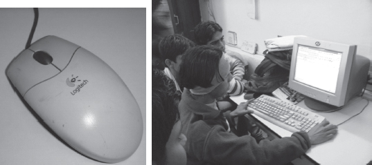
Figure 4.3 (i) Mouse, (ii) A user working with a mouse
Physical Mouse has a rubber ball on the bottom side that protrudes when the mouse is moved. It requires a smooth, dust free surface, such as a mouse pad, on which it is rolled.
Optical Mouse uses a Light Emitting Diode (LED) and a sensor to detect the movement of mouse. Optical mouse requires an opaque flat surface underneath it. Optical mouse was introduced by Microsoft in 1999. Optical mouse is better than physical mouse as there is no moving part that can cause wear and tear, and dirt cannot get inside it. A user is working with an optical mouse in Figure 4.3 (ii).
Working In a physical mouse, rollers and sensors are used to sense the direction and rate of movement of mouse. When the ball of mouse moves, the rollers sense the horizontal and vertical movement and sensors sense the speed of movement. This information is passed to computer via the mouse chord. When an optical mouse is moved, a beam of light is reflected from its underside. These pulses of light determine the direction and rate of movement. This information is sent to computer via the mouse chord.
Using the mouse The mouse can be used in five different ways, as follows—
- Pointing points to a location or object on the computer screen. Moving the mouse by hand moves the cursor on computer screen. The cursor moves in the direction in which the mouse moves.
- Left Click or Click means pressing the left button of mouse and releasing it. Clicking is used to select a button, command or icon on the screen.
- Right Click involves pressing the right button on mouse and releasing it. Right click displays a menu that contains options like cut, copy, paste, font, paragraph, etc. for the item on which the mouse is pointing.
- Double Click means pressing the left button of mouse twice successively, without moving the mouse, and then releasing the mouse. It is used to start a program or open a folder.
- Drag and Drop drags an object and drops it at another location. Drag means pointing mouse to an object on screen, pressing the left button of mouse, keeping it pressed and moving the mouse to point to a new location. The object gets dragged to the new location along with the mouse. When the left button of mouse is released, the object gets dropped at the new location. Drag and drop is used for moving folders, files and icons to new locations on the screen.
4.4.2.2 TrackBall
Features Trackball is a device that is a variant of the mouse but has the functionality of mouse. It is easy to use and takes less space than a mouse. Trackball is generally built in laptops since there is no space for the mouse to move on the lap. Trackballs come in various sizes—small and big.
Description Trackball looks like an upside-down mouse. Instead of moving the whole device to move the cursor on computer screen, trackball requires the ball to be rotated manually with a finger. The trackball device remains stationary. The cursor on the computer screen moves in the direction in which the ball is moved. The buttons on trackball are used in the same way as mouse buttons. A trackball is shown in Figure 4.4.
Working Trackball works in the same way as a physical mouse.
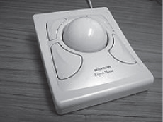
Figure 4.4 Trackball
4.4.2.3 Joystick
Features Joystick (Figure 4.5) is a device which is commonly used for playing video games. Joystick is mainly used to control the speed of the cursor and is thus popular in games involving speed like racing and flying games. The direction of push of the stick and the amount of deflection determines the change in position and the change in speed, respectively.
Description It is a stick with its base attached to a flexible rubber sheath inside a plastic cover. The plastic cover contains the circuit that detects the movement of stick and sends the information to computer. The position of the stick movement is given by the x and y coordinates of the stick.
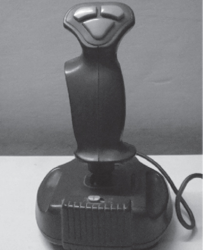
Figure 4.5 Joystick
4.4.2.4 Digitizing Tablet
Features It is an input device used primarily to input drawings, sketches, etc. Digitizing tablet is used for Computer Aided Design (CAD) for the design of buildings, automotive designs, and designing of maps, etc. Figure 4.6 shows a digitizing tablet.
Description Digitizing tablet consists of two parts—electronic tablet and pen. The electronic tablet is a flat bed tablet. The pen looks like a ball pen but has an electronic head. The pen in moved on the tablet. Each position on the tablet corresponds to a fixed position on the screen. Drawings can be made on the tablet using a pen, and is provided as input to computer, where, a location on the tablet corresponds to a specific location on the screen.
Working The tablet contains circuit that can detect the movement of pen on the tablet, convert the movements into digital signals and send the digital signal to the computer.
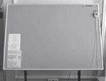
Figure 4.6 Digitizing tablet
4.4.3 Pick Devices
Pick devices are used for providing input to the computer by pointing to a location on the computer monitor. The input data is not typed; the data is entered by pointing the pick device directly on the computer screen. Light pen and touch screen are some common pick devices.
4.4.3.1 Light Pen
Features It is a light sensitive pen-like input device and is used to select objects directly on the computer screen. It is used for making drawing, graphics and for menu selection. Figures and drawings can be made by moving the pen on computer screen.
Description and Working The pen contains a photocell in a small tube. When the pen is moved on the screen, light from the screen at the location of pen causes the photocell to respond. The electric response is transmitted to the computer that can identify the position on screen at which the light pen is pointing. Figure 4.7 shows a user using a light pen on the screen.
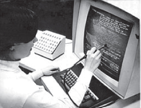
Figure 4.7 Using a light pen
4.4.3.2 Touch Screen
Features It is an input device that accepts input when the user places a fingertip on the computer screen. The computer selects the option from the menu of screen to which the finger points. Touch screen are generally used in applications like Automated Teller Machine (ATM), public information computers like hospitals, airline reservation, railway reservation, supermarkets, etc. (Figure 4.8).

Figure 4.8 Touch screen of an ATM
Description Touch screen consists of a clear glass panel that is placed over the view area of computer screen. In addition to the glass panel with sensors, it has a device driver, and a controller that translates the information captured by the glass panel sensors to a form that the computer can understand.
Working Touch screens have an infrared beam that criss-cross the surface of screen. When a fingertip is touched on the screen, the beam is broken, and the location is recorded. Some touch screens have ultrasonic acoustic waves that cross the surface of screen. When a fingertip is touched on the screen, the wave is interrupted, and the location is recorded. The recorded location is sent to the computer via the controller of touch screen, in a form that the computer can understand.
4.5 SOURCE DATA ENTRY DEVICES
Source data entry devices are used for audio input, video input and to enter the source document directly to the computer. Source data entry devices do not require data to be typed-in, keyed-in or pointed to a particular location.
4.5.1 Audio Input Device
Audio input can be provided to the computer using human voice or speech. Audio input to the computer can be used for different purposes. It can be used for making telephone calls, for audio and video conferencing over Internet, to record voice, to create audio files and embed these files to be sent over e-mail, or, to translate spoken words into text, etc.
Audio input devices like a microphone is used to input a person’s voice into the computer. A sound card (Figure 4.9 (i)) translates analog audio signals from microphone into digital codes that the computer can store and process. Sound card also translates back the digital sound into analog signals that can be sent to the speakers. Translating spoken words into text is also known as speech recognition or voice recognition. The audio input along with the software for voice recognition forms the speech recognition system or voice recognition system.
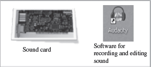
Figure 4.9 (i) Sound card, (ii) Audacity software
The computer can be operated using voice commands. The user can dictate the commands to the computer, instead of typing them. The computer has to be trained to recognize the voice of user using the speech patterns and pronunciation of words. The system thus adapts to the voice of user. Speech recognition systems are costly and difficult to develop. They are generally used by people who have difficulty in typing, people with disabilities or by corporate world for dictation. Audio input can be recorded on an mp3 recorder and provided as an input to computer. Open source software like Audacity is used for recording and editing of audio files (Figure 4.9 (ii)).
4.5.2 Video Input Device
Video input is provided to the computer using video camera and digital camera (Figure 4.10). Video camera can capture full motion video images. The images are digitized and can be compressed and stored in the computer disk. Webcam is a common video camera device. It is placed on the computer above the screen to capture the images of the user who is working on the computer. A video capture card allows the user to connect video devices like camcorders to the computer.
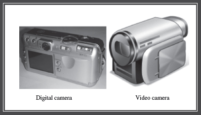
Figure 4.10 Video input devices
Digital camera works like video camera but can capture still images. The digital camera digitizes images, compresses them and stores them on a memory card like flash memory. The information from the digital camera can be brought into the computer and stored. The video files can be edited using software like VLC media player. Computer vision is an area of computer science that deals with images. Computer vision has applications in areas like robotics and industrial processing.
4.5.3 Optical Input Devices
Optical input devices allow computers to use light as a source of input. Scanner is an example of optical input device. Other common optical input devices are magnetic ink character reader used for Magnetic Ink Character Recognition (MICR), optical mark reader used for Optical Mark Recognition (OMR), optical character reader for Optical Character Recognition (OCR) and Barcode Reader.
4.5.3.1 Scanner
Scanner is an input device that accepts paper document as an input. Scanner is used to input data directly into the computer from the source document without copying and typing the data. The input data to be scanned can be a picture, a text or a mark on a paper. It is an optical input device and uses light as an input source to convert an image into an electronic form that can be stored on the computer. Scanner accepts the source paper document, scans the document and translates it into a bitmap image to be stored on the computer. The denser the bitmap, the higher is the resolution of the image. The quality of scan increases with the increase in resolution. Scanners come with utility software that allow the stored scanned documents to be edited, manipulated and printed. Hand-held scanner and flat-bed scanner are the two common types of scanners.
- Hand-held Scanners are portable and are placed over the document to be scanned. They consist of light emitting diodes. The scanned documents are converted and stored as an image in the computer memory. Hand-held scanners have to be moved at a constant speed over the document to be scanned, to get good quality scans. They are preferably used for low volume of documents, small pictures or photos. They are difficult to use if there is a need to scan a full page document. Some of the documents that are primarily scanned using hand-held scanners are price tags, label and ISBN number on books.
- Flat-bed Scanners provide high quality scan in a single pass. It is a box shaped machine similar to a photocopy machine and has a glass top and a lid that covers the glass (Figure 4.11). The document to be scanned is placed on the glass top, which activates the light beam beneath the glass top and starts the scan from left to right. They are largely used to scan full page documents.
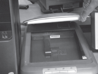
Figure 4.11 Flat bed scanner
4.5.3.2 Optical Character Recognition (OCR)
OCR is a technique for the scanning of a printed page, translating it, and then using the OCR software to recognize the image as ASCII text that is editable. OCR uses optical character reader for recognition. The optical character reader stores the scanned image as bitmap image which is a grid of dots. Thus, you cannot edit the text that has been scanned. To edit the scanned text, you need OCR software. The OCR software translates the array of dots into text that the computer can interpret as words and letters. To recognize the words and letters of text, the OCR software compares the pattern on the scanned image with the patterns stored inside the computer. The text files generated via OCR can be stored in different formats. Figure 4.12 shows the working of the OCR system.
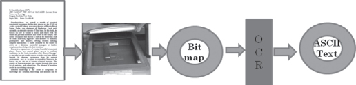
Figure 4.12 OCR system
4.5.3.3 Magnetic Ink Character Recognition (MICR)
MICR is used in banks to process large volumes of cheques (Figure 4.13). It is used for recognizing the magnetic encoding numbers printed at the bottom of a cheque. The numbers on the cheque are human readable, and are printed using an ink which contains iron particles. These numbers are magnetized. MICR uses magnetic ink character reader for character recognition. When a cheque is passed through Magnetic Ink Character Reader, the magnetic field causes the read head to recognize the characters or numbers of cheque. The readers are generally used in banks to process the cheques. The numbers in the bottom of the cheque include the bank number, branch number and cheque number. The reading speed of MICR is faster than OCR.
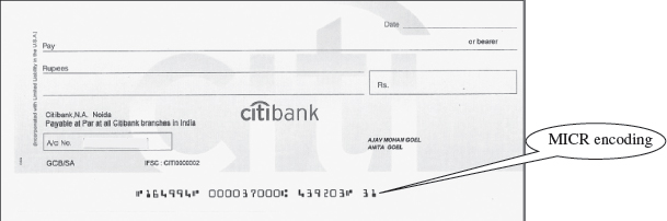
Figure 4.13 MICR encoded cheque
4.5.3.4 Optical Mark Recognition (OMR)
OMR is used to detect marks on a paper. The marks are recognized by their darkness. OMR uses an optical mark reader to read the marks. The OMR reader scans the forms, detects the mark that is positioned correctly on the paper and is darker than the surrounding paper, and passes this information to the computer for processing by application software. For this, it uses a beam of light that is reflected on the paper with marks, to capture presence and absence of marks. The optical mark reader detects the presence of mark by measuring the reflected light. The pattern of marks is interpreted and stored in the computer.
OMR is widely used to read answers of objective type tests, where the student marks an answer by darkening a particular circle using a pencil. OMR is also used to read forms, questionnaires, order forms, etc. Figure 4.14 shows a marked OMR answer sheet.
4.5.3.5 Barcode Reader
Barcodes are adjacent vertical lines of different width that are machine readable. Goods available at supermarkets, books, etc. use barcode for identification. Barcodes are read using reflective light by barcode readers. This information is input to the computer which interprets the code using the spacing and thickness of bars. Hand-held barcode readers are generally used in departmental stores to read the labels, and in libraries to read labels on books. Figure 4.15 (i) shows a barcode printed at the back of a book.
Barcode readers (Figure 4.15 (ii)) are fast and accurate. They enable faster service to the customer and are also used to determine the items being sold, number of each item sold or to retrieve the price of item.
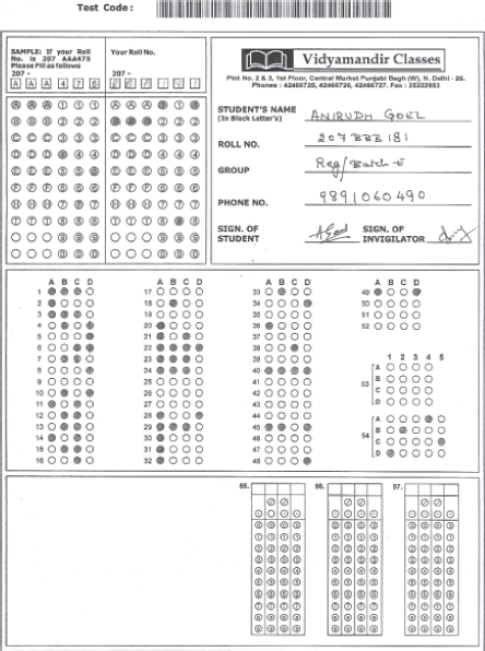
Figure 4.14 OMR answer sheet

Figure 4.15 (i) Barcode of a book, (ii) Barcode reader
4.6 OUTPUT DEVICES
Output devices provide output to the user, which is generated after processing the input data. The processed data, presented to the user via the output devices could be text, graphics, audio or video. The output could be on a paper or on a film in a tangible form, or, in an intangible form as audio, video and electronic form. Output devices are classified as follows—
- Hard Copy Devices
- Printer
- Plotter
- Computer Output on Microfilm (microfiche)
- Soft Copy Devices
- Monitor
- Visual Display Terminal
- Video Output
- Audio Response
Figure 4.16 (i) shows a soft copy output on an LCD monitor and Figure 4.16 (ii) is a hard copy output on paper. The output device receives information from computer in a machine readable form. The received output is translated to a human understandable form. The translation is done using the output interface of output device.
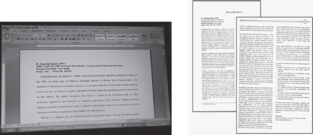
Figure 4.16 (i) Soft copy output, (ii) Hard copy output
4.6.1 Hard Copy Devices
The output obtained in a tangible form on a paper or any surface is called hard copy output. The hard copy can be stored permanently and is portable. The hard copy output can be read or used without a computer. The devices that generate hard copy output are called hard copy devices. Printer, plotter and microfiche are common hard copy output devices.
4.6.1.1 Printer
A printer prints the output information from the computer onto a paper. Printers are generally used to print textual information, but nowadays printers also print graphical information. The print quality (sharpness and clarity of print) of the printer is determined by the resolution of the printer. Resolution is measured in dots per inch (dpi). Printers with a high resolution (more dpi) provide better quality output. Different kinds of printers are available for different types of applications. Printers are classified into two categories—impact printer and non-impact printer.
Impact printers use the typewriter approach of physically striking a typeface against the paper and inked ribbon. Impact printers can print a character or an entire line at a time. Impact printers are low-cost printers useful for bulk printing. Dot matrix printers, daisy wheel printers and drum printers are examples of impact printers.
- Dot Matrix Printers (Figure 4.17) print one i character at a time. The speed of dot matrix printer lies between 200 and 600 characters per second (cps) and their resolution ranges from 72 to 360 dpi. Dot matrix printers normally come in two sizes—80 column printer and 132 column printer. Dot matrix printers can print alphanumeric characters, special characters, charts and graphs. They can print only in black and white. Some dot matrix printers can print in both directions - left to right and right to left. Dot matrix printers are commonly used for printing in applications like payroll and accounting.
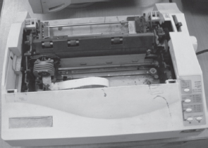
Figure 4.17 Dot matrix printer
- Daisy Wheel Printers (Figure 4.18) print one character at a time. They produce letter quality document which is better than a document printed by a dot matrix printer. The speed of daisy wheel printers is about 100 cps. The print head of the printer is like a daisy flower, hence the name. These printers are slow, can only print text (not graphics), and are costly in comparison to dot matrix printers. Daisy wheel printers are used where high quality printing is needed and no graphics is needed.
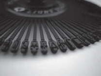
Figure 4.18 Daisy wheel for printers
- Drum Printers are line printers. They are expensive and faster than character printers but produce a low quality output. They can print 200–2500 lines per minute. Drum printers are generally used for voluminous print outputs.
Non-Impact Printers do not hit or impact a ribbon to print. They use electro-static chemicals and ink-jet technologies. Non-impact printers are faster and quieter than impact printers. They produce high quality output and can be used for printing text and graphics both in black and white, and color. Ink-jet printers and laser printers are non-impact printers.
- Ink-jet Printers spray ink drops directly on the paper like a jet (Figure 4.19 (i)). Their resolution is more than 500 dpi. They produce high quality graphics and text. Ink-jet printers are commonly found in homes and offices.
- Laser Printers (Figure 4.19 (ii)) provide highest quality of text and graphics printing. Laser printers process and store the entire page before printing and are also known as page printers. The laser printer can print 5–24 pages of text per minute and their resolution ranges from 400 to 1200 dpi. They are faster and expensive than impact printers. Laser printers are used in applications requiring high quality voluminous printing.

Figure 4.19 (i) Inkjet printer, (ii) Laser printer
4.6.1.2 Plotter
A plotter (Figure 4.20) is used for vector graphics output to draw graphs, maps, blueprints of ships, buildings, etc. Plotters use pens of different colors (cyan, magenta, yellow and black) for drawing. Plotters draw continuous and accurate lines, in contrast to printers where a line is drawn as closely spaced dots. Plotter is a slow output device and is expensive. Plotters are of two kinds—drum plotter and flatbed plotter. In a drum plotter, pens mounted on the carriage are stationary and move only horizontally; for vertical movement, the drum on which the paper is fixed moves clockwise and anti-clockwise. In a flatbed plotter, the paper is fixed on a flat bed. The paper is stationary and the pens mounted on the carriage move horizontally and vertically to draw lines. Plotters are mainly used for drawings in AUTOCAD (computer assisted drafting), Computer Aided Design (CAD) and Computer Aided Manufacturing (CAM) applications.
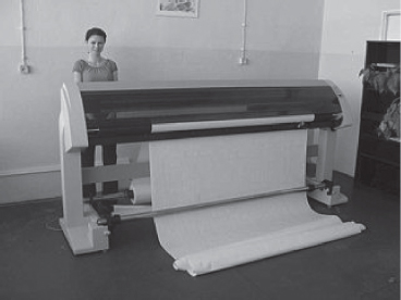
Figure 4.20 Plotter
4.6.1.3 Computer Output on Microfilm
A microfilm (Figure 4.21) is in a fiche or roll format, and is used to record computer output directly from the computer tape or cartridge. Computer Output on Microfilm (COM) is a high speed and low cost process. It can produce data in microfilm form at a much faster speed from that of a paper printer. The standard roll film is 16 mm wide with a film image that is 1/24 of the original document. The copy of the image on microfilm retains its original clarity. Microfilm can be indexed to facilitate retrieving information from it. For reading images stored on microfilm, a microfilm reader is used. A screen is used for viewing the enlarged images. COM is suited for storing large amounts of data for manuals and archive records for long periods of time that have to be referenced occasionally. COM is used for storing output in banking and insurance applications, medical X rays, etc.
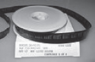
Figure 4.21 Microfilm
4.6.2 Soft Copy Devices
The output obtained in an intangible form on a visual display, audio unit or video unit is called soft copy output. The soft copy allows corrections to be made, can be stored, and, can be sent via E– to other users. The soft copy output requires a computer to be read or used. The devices that generate soft copy output are called soft copy devices. Visual output devices like computer monitor, visual display terminal, video system and audio response system are common soft copy output devices.
4.6.2.1 Monitor
Monitor is a common output device. The monitor is provided along with the computer, to view the displayed output. A monitor is of two kinds - monochrome display monitor and color display monitor. A monochrome display monitor uses only one color to display text and color display monitor can display 256 colors at one time. The number of colors displayed by a color monitor varies with the kind of color adapter attached to it—CGA, EGA, VGA, XGA and SVGA. The CGA monitor supports four colors and SVGA supports around 16,000,000 colors. Monitors are available in various sizes like 14, 15, 17, 19 and 21 inches.
An image on the monitor is created by a configuration of dots, also known as pixels. The clarity of image on the computer screen depends on three factors—
- Resolution of Screen—the number of pixels in horizontal and vertical direction. More the number of pixels, the sharper is the image. The common resolution of computer screen is 800x600 and 1024x768,
- Dot Pitch—the diagonal distance between two colored pixels on a display screen, and
- Refresh Rate—the number of times per second the pixels are recharged so that their glow remains bright.
Monitors may be Cathode Ray Tube (CRT) monitors (Figure 4.22) that look like a television or Liquid Crystal Display (LCD) monitors (Figure 4.23, Figure 4.24) that have a high resolution, flat screen, flat panel display. Nowadays, LCD monitors are generally used.
4.6.2.2 Visual Display Terminal
A monitor and keyboard together are known as Visual Display Terminal (VDT). A keyboard is used to input data and monitor is used to display the output from the computer. The monitor is connected to the computer by a cable. Terminals are categorized as dumb, smart and intelligent terminals. The dumb terminals do not have processing and programming capabilities. Smart terminals have built-in processing capability but do not have its own storage capacity. Intelligent terminals have both built-in processing and storage capacity.
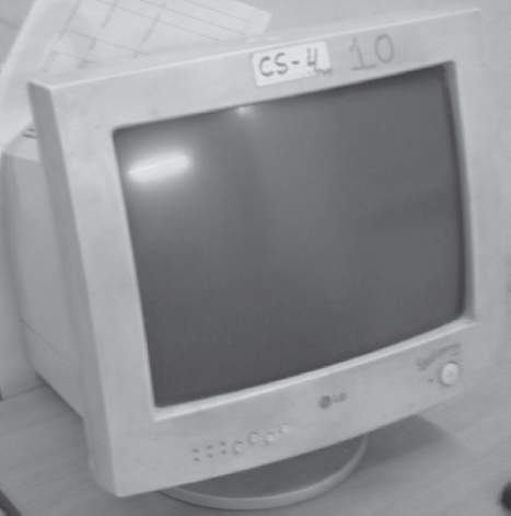
Figure 4.22 CRT monitor
4.6.2.3 Video Output
Screen image projector or data projector (Figure 4.25 (i)) is an output device that displays information from the computer onto a large white screen. The projector is mainly used to display visual output to a large gathering of people required for the purposes of teaching, training, meetings, conference presentations, etc. (Figure 4.25 (ii)).
4.6.2.4 Audio Response
A complete sound system consists of sound card, microphone, speaker and the appropriate software. In addition to recording and playing the sound, the software allows editing of sound, like cutting, copy, amplification and creation of vibrant sound effects.
Audio response provides audio output from the computer. Audio output device like speakers, headset or headphone (Figure 4.26) is used for audio output sound from computer. The signals are sent to the speakers via the sound card that translates the digital sound back into analog signals. The audio response from the computer may be generated by synthesizing the input human speech to give audio output, or may be a result of a set of rules that are used to create artificial speech.
Audio output is commonly used for customer service in airlines, banks, etc. It is also used in video conferences, surveys, etc. Audio response is used by visually impaired to read information from the screen. For speech impaired people, audio response helps them to communicate with other people.
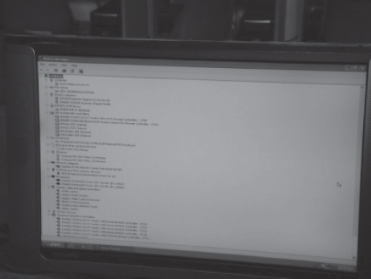
Figure 4.23 LCD monitor
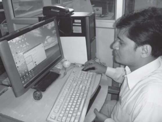
Figure 4.24 A user viewing the output on a LCD monitor

Figure 4.25 (i) LCD projector, (ii) A presentation in progress using LCD projector
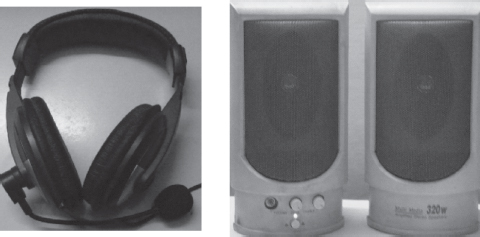
Figure 4.26 Headphone and speakers
4.7 I/O PORT
The peripheral devices can be connected to computer in several ways. Devices such as network adapters and sound cards are connected to expansion slots inside the computer. Printers and scanners are connected to ports on the backside of the computer. Also in a portable computer, the PC Card connects to the PC Card slot on it.
The I/O ports are the external interfaces that are used to connect input and output devices like printer, modem and joystick to the computer. The I/O devices are connected to the computer via the serial and parallel ports, Universal Serial Bus (USB) port, Firewire port, etc. (Figure 4.27).
- Parallel Port A parallel port is an interface for connecting eight or more data wires. The data flows through the eight wires simultaneously. They can transmit eight bits of data in parallel. As a result, parallel ports provide high speed data transmission. Parallel port is used to connect printer to the computer.
- Serial Port A serial port transmits one bit of data through a single wire. Since data is transmitted serially as single bits, serial ports provide slow speed data transmission. Serial port is used to connect external modems, plotters, barcode reader , etc.
- USB Port Nowadays, USB is a common and popular external port available with computers. Normally, two to four USB ports are provided on a PC. USB allows different devices to be connected to the computer without requiring re-boot of the computer. USB also has the plug and play feature which allows devices ready to be run simply by plugging them to the USB port. A single USB port can support connection of up to 127 devices.
- Firewire (IEEE 1394) It is used to connect audio and video multimedia devices like video camera. It is an expensive technology and is used for large data movement. Hard disk drive and new DVD drives connect through firewire. It has data transfer rate of up to 400 MB/sec.
In addition to the above ports, other ports also exist like Musical Instrument Digital Interface (MIDI) port to connect musical instruments like synthesizers and drum machines, PC expansion boards, and PC card and many more.
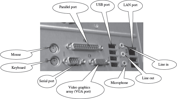
Figure 4.27 Backside of computer cabinet with different ports
4.8 WORKING OF I/O SYSTEM
The working of I/O system combines I/O hardware and I/O software. The I/O hardware includes ports, buses and device controllers for different devices, and I/O devices. The I/O software is the device driver software that may be embedded with operating system or comes with each device. The working of I/O system is described as follows—
- I/O Devices are attached to computer via the ports of computer. There are many standard ports available on the backside of the computer case like serial port and parallel port. If one or more devices use a common set of wires, it is called a bus. For example, PCI bus, PCI Express bus, etc.
- Device Controller operates on a bus, a port or a device. It controls the signals on the wires of port or bus. The controllers have one or more registers for data and control signals. Controller may be simple like a serial port controller for a serial port, or, complex like a SCSI controller. Some devices have their own built-in controllers.
- Device Driver is software via which the operating system communicates with the device controllers. Each device has its own device driver, and a device controller which is specific to the device. The device drivers hide the differences among the different device controller and present a uniform interface to the operating system.
- Application programs use an I/O device by issuing commands and exchanging data with the device driver. The device driver provides correct commands to the controller, interprets the controller register, and transfers data to and from device controller registers as required for the correct device operation.
Operating system ------ Device Drivers -------- Device Controllers -------- Devices
SUMMARY
- A user interacts with the computer via Input-Output (I/O) devices. The peripheral devices are attached externally to the computer machine.
- Input unit accepts input data from the user via input device, transforms the input data in computer acceptable form and provides the transformed input data for processing.
- Output unit accepts output data from computer via output device, transforms the output information to human readable form and provides the transformed output to user.
- Some devices are both input and output devices. Hard disk drive, floppy disk drive, optical disk drives are examples of inputoutput devices.
- Keyboard is used to enter text data. Standard keyboard contains 101 keys to 110 keys.
- Mouse is a small hand-held pointing input device used to enter data by pointing to a location on the computer monitor screen.
- Trackball looks like an upside-down mouse and requires the ball to be rotated manually with a fi nger.
- Joystick is a stick with its base attached to a fl exible rubber sheath inside a plastic cover. It is used for playing video games.
- Digitizing tablet has a fl at bed tablet, and a pen with an electronic head which is moved on the tablet. Digitizing tablet is used for computer aided design of buildings, maps, etc.
- Light pen contains a photocell in a small tube and is used to select objects directly on the computer screen.
- Touch screen is a clear glass panel that is placed over the view area of the computer screen. The user uses the fi ngertip on the computer screen to select an option. It is used in ATMs.
- Audio input devices use a microphone to input a person’s voice, a sound card to translate analog audio signals from microphone into digital codes and speech recognition to translate spoken words into text.
- Video input is provided using video camera and digital camera. Computer vision is an area of computer science that deals with images.
- Scanner is used to input data directly into the computer from the source document without copying and typing the data. A scanner can be a hand-held scanner or flat bed scanner.
- OCR is a technique for the scanning of a printed page, translating it, and then using the OCR software to recognize the image as ASCII text that is editable.
- MICR is used in banks to process large volumes of cheques. It is used to recognize the magnetic encoding numbers printed at the bottom of a cheque.
- OMR uses an optical mark reader to detect marks on a paper. OMR is widely used to read answers of objective type tests, questionnaires, etc.
- Barcodes are adjacent vertical lines of different width that are machine readable. Barcode reader reads the barcode. They are used to read labels in departmental stores and in libraries.
- Printer prints the output onto a paper. Plotter is used for drawing maps, blueprints of ships, buildings, etc.
- Impact printers are those in which the typeface strikes against the paper. Dot matrix printers, daisy wheel printers and drum printers are examples of impact printers.
- Non-Impact printers do not hit or impact a ribbon to print. Ink-jet printers and laser printers are non-impact printers.
- COM is a high‒speed and low-cost process to record computer output directly from the computer tape on a microfilm. It is used to store manuals and for archiving of records.
- Monitor is attached to the computer on which the output is displayed. The clarity of image on the computer screen depends on the resolution of screen, the dot pitch, and the refresh rate.
- Screen image projectors display information from the computer onto a large white screen.
- Audio output device like speakers, headset or headphone are used to output sound from the computer system.
- I/O ports connect the I/O devices to the computer. Serial and parallel ports, USB port and Firewire are some of the commonly used I/O ports.
- I/O system uses the I/O hardware (buses, ports, device controllers and I/O devices) and the I/O software (device drivers) for its working.
KEYWORDS
Audio Response System |
Digital Camera |
Flatbed Plotter |
Barcode Reader |
Digitizing Tablet |
Flat-bed Scanner |
Bus |
Dot matrix Printer |
Hand-held Scanner |
Characters per Second (cps) |
dots per inch (dpi) |
Hard Copy Devices |
Computer Output on |
Double Click |
Headphone |
Microfilm (COM) |
Drag and Drop |
Impact Printer |
Daisy wheel Printer |
Drum Plotter |
Ink-jet Printer |
Device Controller |
Drum Printer |
Input Device |
Device Driver |
Firewire Port |
Input Interface |
Input-Output Device |
Optical Character |
Pointing Devices |
Input-Output (I/O) |
Recognition (OCR) |
Right Click |
Unit |
Optical Mark Recognition |
Scanner |
Input Unit |
(OMR) |
Serial port |
I/O Port |
Optical Mouse |
Soft Copy Devices |
Joystick |
Optical Scanner |
Sound Card |
Keyboard |
Output Devices |
Speakers |
Laser Printer |
Output Interface |
Speech recognition |
Left Click |
Output Unit |
Touch Screen |
Light Pen |
Page Printer |
Track Ball |
Magnetic Ink Character |
Parallel port |
USB Port |
Recognition (MICR) |
Peripheral Devices |
Video Camera |
Microphone |
Physical Mouse |
Video Input |
Monitor |
Pick Devices |
Video Output System |
Mouse |
Pixels |
Visual Display Terminal |
Non-Impact Printer |
Plotter |
(VDT) |
QUESTIONS
Section 4.1–4.2
1. Define peripheral devices.
2. Explain in detail the input unit of the computer.
3. What is the purpose input interface?
4. Explain in detail the output unit of the computer.
5. What is the purpose of output interface?
6. Name three input-output devices.
Section 4.3–4.4.1
7. Show the classification of the input devices.
8. Describe the features of the keyboard.
9. Give a description of the keyboard.
10. What is a cursor?
11. Explain the working of a keyboard
12. Name the different sections of a keyboard.
Section 4.4–4.4.2.4
13. Name three pointing devices.
14. Describe the features of the mouse.
15. Give a description of the mouse.
16. Explain the working of a physical mouse and optical mouse.
17. Describe a physical mouse.
18. Give description of an optical mouse.
19. What is right click, left click and double click when you use a mouse?
20. What is the purpose of drag and drop when you use a mouse?
21. Describe the features of trackball.
22. What is a trackball?
23. In which areas is joystick mostly used?
24. Give a brief description of joystick along with its features.
25. Name an application of digitizing tablet.
26. Describe a digitizing tablet.
Section 4.4.3–4.5.3.5
27. Name an application where a light pen is used.
28. Describe a touch screen. Give its features and explain its working.
29. Name some applications where you use a touch screen.
30. Explain the working of audio input devices.
31. Why is a sound card used?
32. Define speech recognition.
33. _____ and_____are examples of video input devices.
34. Name an application where computer vision is used.
35. Name three optical scanner devices.
36. Why is a scanner used?
37. Describe hand-held scanners and flat-bed scanners.
38. What is the purpose of OCR software in optical character recognition?
39. An application where MICR is commonly used is_____.
40. Name an application of OMR.
41. How does optical character reader recognize characters?
42. How does magnetic ink character reader recognize the magnetic characters?
43. How does optical mark reader recognize marks?
44. What is the use of barcode reader?
Section 4.6–4.6.1.1
45. Dot Matrix printers come in two sizes_____ column printer and _____ column printer.
46. The sharpness and clarity of print of the printer is determined by the _____ of printer.
47. Resolution of printer is measured in_____.
48. Describe a dot-matrix printer.
49. Describe a daisywheel printer.
50. Dot matrix and daisy wheel printers are character printer but drum printer is a _____ printer and laser printer is a _____ printer.
51. Describe non-impact printers.
Section 4.6.1.2–4.6.2.4
52. What is the use of a plotter?
53. Plotters are of two kinds— _____plotter _____ and _____ plotter.
54. Name two applications where plotters are used.
55. Define a microfilm.
56. When do we use a microfilm?
57. Give a description of the monitor.
58. Define the resolution of the screen.
59. Define the refresh rate of the screen.
60. Define the dot pitch of the screen.
61. The common resolution of computer screen is _____ and_____.
62. Describe the three factors on which the clarity of image on the computer screen depends.
63. Name the three factors on which the clarity of image on the computer screen depends.
64. Name some color adapters.
65. What is a visual display terminal?
66. Why are screen image projectors used?
67. Describe how the audio response system works.
68. Name two applications of audio response system.
Section 4.7–4.8
69. Name the different types of I/O ports.
70. Name at least one device each that can be connected to the serial port, parallel port, USB port, MIDI port and firewire.
71. Explain the working of the I/O system.
72. What is the purpose of ports, buses and controllers in the I/O system?
73. What is a device driver?
74. What is the use of the device driver?
75. Is device controller a hardware or software?
76. Is device driver a hardware or software?
Extra Questions
77. Give full form of the following abbreviations
- I/O
- LED
- CAD
- ATM
- MICR
- OMR
- OCR
- dpi
- cps
- CAM
- COM
- CRT
- LCD
- VDT
- USB
- MIDI
78. Write short notes on
- Input-iutput unit
- Input Unit
- Output unit
- Keyboard
- Mouse
- Trackball
- Joystick
- Digitizing tablet
- Light pen
- Touch screen
- Input devices
- Audio input device
- Video input device
- Optical input devices
- Scanner
- MICR
- OMR
- OCR
- Printer
- Impact printers
- Non-impact printers
- Plotter
- Computer output on microfilm
- Monitor
- Visual display terminal
- Video output
- Audio response
- I/O ports
- Working of the I/O system
79. Give differences between the following
- Input unit and output unit
- Physical mouse and Optical mouse
- Pointing devices and Pick devices
- Hand-held scanners and Flat-bed scanners
- Impact printers and Non-Impact printers
- Dot matrix printers and Daisy wheel printers
- Ink-jet printers and Laser printers