
9
DATA COMMUNICATION AND COMPUTER NETWORK
Contents
- Importance of networking—Resource sharing, information sharing, as a communication medium, back-up and support
- Data transmission media—Twisted pair, coaxial cable, optical fiber, RF transmission, microwave transmission, satellite transmission
- Data transmission across media
- Transmission modes—Simplex, halfduplex, full-duplex
- Transmission speed—Bandwidth, throughput, attenuation, distortion
- Fundamentals of transmission— Electromagnetic waves, signals
- Analog and digital signals
- Modulation and demodulation— Amplitude, frequency, phase shift
- Multiplexing—FDM, WDM
- Asynchronous and synchronous transmission
- Data transmission and data networking
- Switching—Circuit switching, message switching, packet switching
- Computer network
- Network types—LAN, MAN, WAN
- Network topologies—Bus, ring, star
- Communication protocol—The seven layers of OSI model
- Network devices—NIC, repeater, bridge, hub, switch, router, gateway
- Wireless networking—Bluetooth technology, wireless LAN, wireless WAN
Why this chapter
As opposed to a stand-alone computer, connected computers facilitate exchange of information. To connect the computers, you need a data transmission media and understand how data gets transmitted across the media. You can create a network of different types of computers across a room, building, city, state or the world. The purpose of this chapter is to introduce you to the data communication and the computer network.
9.1 INTRODUCTION
The communication process involves—sender of information, receiver of information, language used for communication, and medium used to establish the communication. Communication between computers also follows a similar process.
This chapter discusses the data communication and the computer networks. The section on data communication discusses the media used for transmission of data, how data can be transferred across the communication media and the relationship between data transmission and data networking. The section on computer network discusses different network types, network topologies, communication protocol and network communicating devices. A brief explanation of wireless networks is also provided.
9.2 IMPORTANCE OF NETWORKING
Networking of computers provides a communication link between the users, and provides access to information. Networking of computers has several uses, described as follows:
- Resource Sharing—In an organization, resources such as printers, fax machines and scanners are generally not required by each person at all times. Moreover, for small organizations it may not be feasible to provide such resources to each individual. Such resources can be made available to different users of the organization on the network. It results in availability of the resource to different users regardless of the physical location of the resource or the user, enhances optimal use of the resource, leads to easy maintenance, and saves cost too (Figure 9.1).
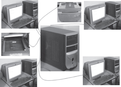
Figure 9.1 A network of computers, printer and scanner
- Sharing of Information—In addition to the sharing of physical resources, networking facilitates sharing of information. Information stored on networked computers located at same or different physical locations, becomes accessible to the computers connected to the network.
- As a Communication Medium—Networking helps in sending and receiving of electronic-mail (e-mail) messages from anywhere in the world. Data in the form of text, audio, video and pictures can be sent via e-mail. This allows the users to communicate online in a faster and cost effective manner. Video conferencing is another form of communication made possible via networking. People in distant locations can hold a meeting, and they can hear and see each other simultaneously.
- For Back-up and Support—Networked computers can be used to take back-up of critical data. In situations where there is a requirement of always-on computer, another computer on the network can take over in case of failure of one computer.
9.3 DATA TRANSMISSION MEDIA
The data is sent from one computer to another over a transmission medium. The transmission media can be grouped into guided media, and unguided media.
In the guided media, the data signals are sent along a specific path, through a wire or a cable. Copper wire and optical fibers are the most commonly used guided media. Copper wire transmits data as electric signals. Copper wires offer low resistance to current signal, facilitating signals to travel longer distances. To minimize the effect of external disturbance on the copper wire, two types of wiring is used—(1) Twisted Pair, and (2) Coaxial Pair. Optical fibers transmit data as light signals.
In the unguided media, the data signals are not bounded by a fixed channel to follow. The data signals are transmitted by air. Radio, microwave, and satellite transmissions fall into this category.
Now let’s discuss both the guided and the unguided data transmission media.
9.3.1 Twisted Pair
- A twisted pair cable consists of four pairs of copper wires coated with an insulating material like plastic or Teflon, twisted together. The twisting of wires reduces electromagnetic interference from external sources.
- Twisted pair cabling is often used in data networks for short and medium length connections because of its relatively lower costs compared to optical fiber and coaxial cable.
- Twisted pair is of two kinds—Shielded Twisted Pair (STP), and Unshielded Twisted Pair (UTP).
- STP cable has an extra layer of metal foil between the twisted pair of copper wires and the outer covering. The metal foil covering provides additional protection from external disturbances. However, the covering increases the resistance to the signal and thus decreases the length of the cable. STP is costly and is generally used in networks where cables pass closer to devices that cause external disturbances.
- UTP is the most commonly used medium for transmission over short distances up to 100m. Out of the four pairs of wires in a UTP cable, only two pairs are used for communication. Figure 9.2 shows the cross-section of STP and UTP cables.
- UTP cables are defined in different categories. The commonly used UTP cable is the Cat-5 cable which is used with fast Ethernet.
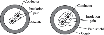
Figure 9.2 Cross section of (a) UTP (b) STP
9.3.2 Coaxial Cable
- A coaxial cable (Figure 9.3) has a single inner conductor that transmits electric signals; the outer conductor acts as a ground. The two conductors are separated by insulation. The inner conductor, insulator, and the outer conductor are wrapped in a sheath of Teflon or PVC.
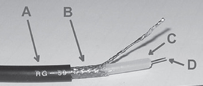
Figure 9.3 Coaxial cable (A: outer plastic sheath, B: woven copper shield, C: inner dielectric insulator, D: copper core)
- The copper wire is used for both inner and outer conductor. The signal is transmitted over the surface of the inner conductor.
- In an ideal coaxial cable the electromagnetic field carrying the signal exists only in the space between the inner and outer conductors. This allows coaxial cable runs to be installed next to metal objects such as gutters without the power losses that occur in other transmission lines, and provides protection of the signal from external electromagnetic interference.
- A thicker coaxial cable can transmit more data than a thinner one.
- The commonly used coaxial cable is 10 base 2 that transmits over a distance of 185 m, and 10 base 5 that transmits over a distance of 500 m.
9.3.3 Optical Fiber
- Optical fibers are being used for transmission of information over large distances more cost-effectively than the copper wire connection. Communication systems are now unthinkable without fiber optics.
- Optical fiber transmits data as light signals instead of electric signals.
- An optical fiber cable (Figure 9.4) consists of(1) core–optical fiber conductor (glass) that transmits light, (2) cladding–an optical material that surrounds the core to prevent any light from escaping the core, and (3) jacket—outer covering made of plastic to protect the fiber from damage.
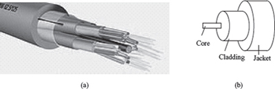
Figure 9.4 (a) Optical fiber (b) Cross section of optical fiber
- Modern optical fiber cables can contain up to a thousand fibers in a single cable, so the performance of optical networks easily accommodate large demands for bandwidth on a point-to-point basis.
- Optical fibers come in two types: (a) Single-mode fibers, and (b) Multi-mode fibers
- Single-mode fibers have small cores (about 3.5 × 10 ~4 inches or 9 microns in diameter) and transmit infrared laser light (wavelength = 1,300 to 1,550 nanometers).
- Multi-mode fibers have larger cores (about 2.5 × 10~3 inches or 62.5 microns in diameter) and transmit infrared light (wavelength ‽ 850 to 1,300 nm) from Light Emitting Diodes (LEDs).
- The Advantages of Optical Fibers over wires are:
- Optical fibers do not cause electrical interference in other cables, since they use light signals.
- Due to much lower attenuation and interference, optical fiber has large advantages over existing copper wire in long-distance and high-demand applications.
- A fiber can carry a pulse of light much farther than a copper wire carrying a signal.
- Optical fiber can carry more information than a wire (light can encode more information than electrical signal).
- A single optical fiber is required for light to travel from one computer to another (two wires are required for electric connection).
- Because signals in optical fibers degrade less, lower-power transmitters can be used instead of the high-voltage electrical transmitters needed for copper wires. Again, this saves your provider and you, money.
- No amplification of the optical signal is needed over distances of hundreds of kilometers. This has greatly reduced the cost of optical networking, particularly over undersea spans where the cost reliability of amplifiers is one of the key factors determining the performance of the whole cable system.
- Optical fibers are ideally suited for carrying digital information, which is especially useful in computer networks.
- They are highly secure as they cannot be tapped and for lack of signal radiation.
- The Disadvantages of Optical Fiber are:
- Installing an optical fiber requires special equipment.
- If a fiber breaks, finding the broken location is difficult.
- Repairing a broken optical fiber is difficult and requires special equipment.
- Due to its high installation costs, they are economical when the bandwidth utilization is high.
9.3.4 Radio Transmission
The electromagnetic radio waves that operate at the adio frequency are also used to transmit computer data. rhis transmission is also known as Radio Frequency RF) transmission (Figure 9.5). The computers using RF ransmission do not require a direct physical connection ike wires or cable. Each computer attaches to an antenna hat can both send and receive radio transmission.
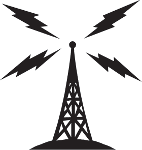
Figure 9.5 Radio transmission
9.3.5 Microwave Transmission
Microwave transmission (Figure 9.6) refers to the technique of transmitting information over a microwave link. Microwaves have a higher frequency than radio waves. Microwave transmission can be aimed at a single direction, instead of broadcasting in all directions (like in radio waves). Microwaves can carry more information than radio waves but cannot penetrate metals. Microwaves are used where there is a clear path between the transmitter and the receiver.

Figure 9.6 Microwave transmission
Microwave transmission has the advantage of not requiring access to all contiguous land along the path of the system, since it does not need cables. They suffer from the disadvantages: a) needing expensive towers and repeaters, and b) are subject to interference from passing airplanes and rain. Because microwave systems are line-of-sight media, radio towers must be spaced approximately every 42 km along the route.
9.3.6 Satellite Transmission
The communication across longer distances can be provided by combining radio frequency transmission with satellites. Geosynchronous satellites are placed in an orbit synchronized with the rotation of the earth at a distance of 36,000 km above the surface of the earth. Geosynchronous satellites appear to be stationary when viewed from the earth. The satellite consists of transponder that can receive RF signals and transmit them back to the ground at a different angle. A ground station on one side of the ocean transmits signal to the satellite which in turn sends the signal to the ground station on the other side of the ocean (Figure 9.7).
9.4 DATA TRANSMISSION ACROSS MEDIA
Transmitting data across media implies sending bits through the transmission medium. Physically, the data is sent as electric signals, radio waves or as light signals. Let’s now discuss the use of electric current to transfer digital information. For this, the bits are encoded and sent as characters.
9.4.1 Transmission Modes
The direction in which data can be transmitted between any two linked devices is of three types—(1) Simplex, (2) Half-duplex, and (3) Full-duplex, or duplex. Simplex transmission is uni-directional data transmission. Of the two linked devices, only one of them can send data and the other one can only receive data. Half–duplex transmission is bi-directional data transmission, but the linked devices cannot send and receive at the same time. When one device is sending data the other can only receive. Full-duplex transmission is bi-directional and the linked devices can send and receive data simultaneously. The linked devices can send data and at the same time receive data. Figure 9.8 shows the different kinds of transmission modes used for interaction.

Figure 9.7 Satellite transmission
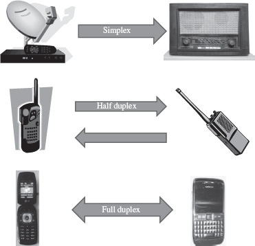
Figure 9.8 Transmission modes
9.4.2 Transmission Speed
- When the signals are transmitted between two computers, two factors need to be considered—(1) Bandwidth, and (2) Distance.
- Bandwidth is the amount of data that can be transferred through the underlying hardware i.e. the communication medium, in a fixed amount of time. Bandwidth is measured in cycles per second (cps) or Hertz (Hz). The bandwidth of the transmission medium determines the data transfer rate.
- Throughput is the amount of data that is actually transmitted between the two computers. Throughput is specified in bits per second (bps). The throughput capability of the communication medium is also called bandwidth. The bandwidth of the communication medium is the upper bound on the throughput, because data cannot be sent at a rate more than the throughput of the communication medium.
- Higher throughput is achieved by using a large part of the electromagnetic spectrum (large bandwidth). Technology that uses large part of the electromagnetic spectrum to achieve higher throughput is known as broadband technology. The technology that uses small part of the electromagnetic spectrum is known as baseband technology.
- Throughput is affected by the distance between the connected computers or devices. Even if a transmission medium is designed for a specific bandwidth, the throughput is affected by the distance of communication.
- The bandwidth of transmission medium is limited by the distance over which the medium needs to transmit the signal. The bandwidth decreases with the increase in the distance between the connected devices. When a signal has to travel long distance, the signal strength decreases; the signal strength is utilized to overcome the resistance offered by the connecting medium (cable or wire). The gradual deterioration of signal strength across long distances is called attenuation.
- Moreover, with increasing distance the external disturbance increases, which causes the signal to deteriorate and results in less amount of data to be transferred. The degradation of signal due to internal or external disturbances is called distortion.
- The bandwidth and distance of the transmission medium is selected so that it offers minimum attenuation and minimum distortion.
- The cat-5 UTP cable has a throughput of 100 Mbps over a distance of 100m. The 10 base2 coaxial cable has a throughput up to 10Mbps over a distance of 185 m. The 10 base 5 coaxial cable has a throughput up to 10Mbps over a distance of 500 m.
9.4.3 Fundamentals of Transmission
Telecommunication systems use electromagnetic waves to transfer information. Electromagnetic waves can travel through transmission media like copper wires, fiber optics or as radio waves. They can also travel in vacuum. Wireless communication uses electromagnetic waves for transmission of information. The transmission media through which the waves propagate are not perfect. As a result, the waves propagated via the transmission media get attenuated and distorted.
The information to be transmitted does not always exist in a form that is compatible with the transmission medium. Waves that are compatible with the transmission medium must be generated to carry information. A signal is a wave that is suitable for carrying information over a transmission medium. Signals can be electric signals, light signals, electromagnetic signals or radio signals. Electric signals are used to carry information through copper wires, light signals for fiber optic cables, and radio signals for carrying information in free space. Electrical signals have limited bandwidth and cannot be used in long distance communication. They need to be amplified or regenerated. Light signals have a high bandwidth and are suited for long distance communication.
9.4.3.1 Analog and Digital Signals
- Information carrying signals are of two types—(a) analog signal, and (b) digital signal (Figure 9.9).

Figure 9.9 (a) Digital signal (b) Analog signal
- Analog Signal: An analog signal is a wave that continuously changes its information carrying properties over time. The wave may vary in amplitude or frequency in response to changes in sound, light, heat, position, or pressure etc. For example a telephone voice signal is analog. The intensity of the voice causes electric current variations. At the receiving end, the signal is reproduced in the same proportion.
- Digital Signal: A digital signal is a wave that takes limited number of values at discrete intervals of time. Digital signals are non-continuous, they change in individual steps. They consist of pulses or digits with discrete levels or values. The value of each pulse is constant, but there is an abrupt change from one digit to the next. Digital signals have two amplitude levels called nodes. The value of which are specified as one of two possibilities such as 1 or 0, HIGH or LOW, TRUE or FALSE, and so on.
- Analog and digital signals are compared on the basis of—(1) impact of noise, (2) loss of information, and (3) introduction of error.
- Analog signal has the potential for an infinite amount of signal resolution. Another advantage with analog signals is that they can be processed more easily than their digital equivalent. The primary disadvantage of the analog signals is the noise. The effects of noise create signal loss and distortion, which is impossible to recover, since amplifying the signal to recover attenuated parts of the signal, also amplifies the noise. Even if the resolution of an analog signal is higher than a comparable digital signal, the difference can be overshadowed by the noise in the signal. In digital systems, degradation can not only be detected, but corrected as well.
- Amplifier is any device or a circuit that changes, usually increases, the amplitude of an analog signal.
- Repeater is an electronic device that receives a signal and retransmits it at a higher level and/or higher power, so that the signal can cover longer distances. With physical media like Ethernet or Wi-Fi, data transmissions can only span a limited distance before the quality of the signal degrades. Repeaters attempt to preserve signal integrity and extend the distance over which data can safely travel. Actual network devices that serve as repeaters usually have some other name. Active hubs, for example, are repeaters. Active hubs are sometimes also called “multiport repeaters,” but more commonly they are just “hubs.”
9.4.3.2 Modulation and Demodulation
- Modulation: Signals consist of two components—the information signal and the carrier signal. The transmission of any signal over some communication medium usually involves modulation of a carrier. Prior to their transmission the information signal and the carrier signal are combined and the process of combining these two signals is called modulation. Characteristics of the carrier signal are varied in proportion to the amplitude of the information-carrying signal. Modulation results in the transfer of the signal information to higher frequency carrier signal. In simple English terms, the information signal sits on top of the carrier signal and rides on it from the receiver to the transmitter.
- Need for Modulation: Let’s understand the need for modulation by using a simple example. Stereophonic radio signal consist of frequency ranges from 30 Hz (Hertz) to 15 KHz (Kilo Hertz). Hence they need a bandwidth of 15 KHz. If ten different radio stations start transmitting their voice signals between 30 Hz and 15 KHz frequencies, then a combination of these signals would only create noise and the receiver would not be able to discriminate between the signals of each radio station. To overcome this, usually the FM broadcast band, used for broadcasting FM radio stations, goes from 87.5 to 108.0 MHz (Mega Hertz). For example a radio channel-1 may be broadcast using a carrier signal of 102 MHz and would typically use band of frequencies between 101.9 to 102.1 MHz. Radio channel2 using a carrier signal of 102.2 MHz would use band of frequencies between 102.1 and 102.3 MHz. Similarly for other channels, the same method of allocation would be followed. This eliminates the problem of discrimination and decoding signals of each of the radio stations at the receiving end.
There are three primary reasons which necessitate modulation:
- To make efficient use of the lines or media used for communication
- To make radio communications feasible: The lower the frequency of signal, the larger is the size of the antenna needed for transmission and reception. A signal of 10 KHz would require an antenna whose dimensions are in the range of a few kilometers.
- To simplify signal processing: It is simpler to design electronic systems for narrow frequency bands.
- At the sending side (transmitter), the signal is superimposed on the carrier wave, which results in a modulated carrier wave. The modulated carrier wave is transmitted. At the receiving end, the receiver is configured to recognize the carrier that the sender is using. The receiver detects the modulation of the carrier wave and reconstructs the data signal.
- The process of segregating the data signal and the carrier signal from the modulated carrier wave is called demodulation. At the receiving end, the carrier wave is discarded after the data signal has been reconstructed.
- Modulation technique did not originate for data communication for computers, but has long been used for radio, television, and telephone communication. For long distance transmission, computer networks use modulation, whether the signals are transmitted over wires, optical fibers, microwave or radio frequency.
- Modulation is of three kinds, which are defined as follows:
- Amplitude Modulation—The amplitude of the carrier wave is modified in proportion to the data signal. The frequency and phase of the carrier signal remains unchanged.
- Frequency Modulation—The frequency of the carrier signal is modified in proportion to the data signal. The amplitude and phase of the carrier signal remains unchanged.
- Phase Shift Modulation—The phase of the carrier signal is modified in proportion to the data signal. The amplitude and frequency of the carrier signal remains unchanged.
- For computer networks, generally phase shift modulation is used. Figure 9.10 shows the different kinds of modulation of a carrier wave with signal.
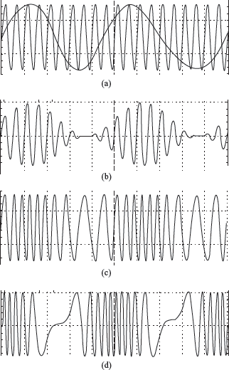
Figure 9.10 (a) Carrier wave with signal (b) Amplitude modulation (c) Frequency modulation (d) Wavelength modulation
- Modem (Figure 9.11) is a device that has both a modulator and a demodulator. Modulator accepts data signals from the computer and modulates the carrier wave accordingly. Demodulator accepts modulated carrier wave and regenerates the original data signal from it. During data communication, modem is attached to the computer, both at the sender and the receiver side. Modems are used with all transmission media like RF modem for RF transmission and optical modem for transmission through fiber optics.
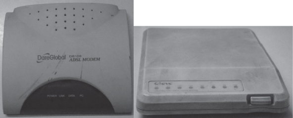
Figure 9.11 Modems
9.4.3.3 Multiplexing
- Transmission medium have varying data carrying capacities. To utilize the full capacity of the transmission medium, computer networks use separate channels that allow sharing of a single physical connection for multiple communication. Multiple carrier signals are transmitted over the same medium at the same time and without interference from each other.
- The combining of multiple signals into a form that can be transmitted over a single link of a communication medium is called multiplexing. Figure 9.12 (a) shows computers connected without multiplexing and Figure 9.12 (b) shows computers connected via a multiplexer.
- Demultiplexing is a technique of separating the merged signals and sending them to the corresponding receivers. The two basic multiplexing techniques are— Frequency Division Multiplexing (FDM) and Wavelength Division Multiplexing (WDM).

Figure 9.12 (a) No multiplexing (b) Multiplexing
- FDM combines different carrier frequencies signals into a single signal of higher bandwidth. The bandwidth of the communication medium link carrying the combined signal is greater than the sum of the bandwidth of the individual signals that are combined. FDM is used for high band—width analog transmission systems like broadband technology.
- WDM is similar to FDM except that FDM involves electromagnetic spectrum below light and WDM involves light signals. WDM uses very high frequencies. WDM combines different light signals coming from different sources into a larger band light signal across a single optical fiber. It also enables bi-directional communications over one strand of fiber.
9.4.3.4 Asynchronous and Synchronous Transmission
- One major difficulty in data transmission is that of synchronising the receiver with the sender. Whenever an electronic device transmits digital (and sometimes analog) data to another electronic device, there must be a certain rhythm established between the two devices, i.e., the receiving device must have some way of knowing, within the context of the fluctuating signal that it is receiving, where each unit of data begins, and ends. The signal must be synchronized in a way that the receiver can distinguish the bits and bytes as the transmitter intends them to be distinguished. Two approaches exist to address the problem of synchronisation—synchronous transmission, and asynchronous transmission.

Figure 9.13 Synchronous communication
- Synchronous communication is the characteristic of a communication system in which the sender must coordinate (i.e. synchronize) with the receiver before sending data (Figure 9.13). The network is designed to move the data at the precise rate, which is not affected by the increase or decrease in network traffic. Voice system network use the synchronous transmission.
- Asynchronous communication is a characteristic of a communication system in which the sender and receiver do not coordinate before the transmission of data (Figure 9.14). The receiver must be prepared to accept data at any time. The sender can wait when no data is available and send when data is available for sending. Most of the data networks use asynchronous transmission. E.g.: RS-232 based serial devices use asynchronous communication.

Figure 9.14 Asynchronous communication
9.5 DATA TRANSMISSION AND DATA NETWORKING
Data transmission at physical level involves the hardware required for handling individual bits and encoding bits in signals. The details of the underlying hardware are generally handled by the engineers who design the hardware.
Any two devices directly linked via a communication medium (point to point communication) can send and receive data, to and from each other respectively (Figure 9.15 a). If a large number of computers need to interact with each other, point to point communication will require direct link between all the computers. This is not a practical solution. The communication circuits and the associated hardware required for communication (like modem) are expensive. Moreover, there may not be a need to transmit data all the time, which will result in the communication medium lying idle for most of the time. For long distance communication, instead of point to point connection, a network of nodes is used as a communication medium. The different computers attached to the network share the communication facility.
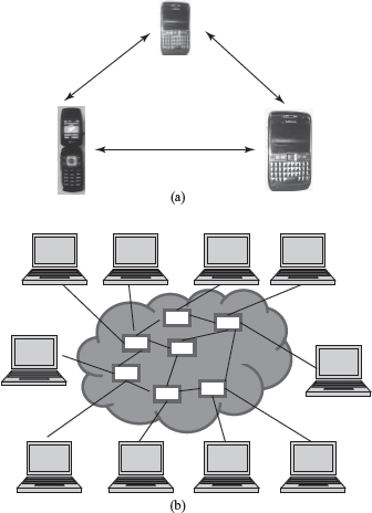
Figure 9.15 (a) Point-to-point communication (b) Switching
The computer network provides a convenient interface that handles sending of multiple bytes of data across the network instead of handling data transmission at physical level.
9.5.1 Switching
A network cannot allow or deny access to a shared communication facility. All computers attached to the network can use it to send and receive data. Networks allow sharing of communication medium using switching (Figure 9.15 b). Switching routes the traffic (data traffic) on the network. It sets up temporary connections between the network nodes to facilitate sending of data. Switching allows different users, fair access to the shared communication medium. There are three kinds of switching techniques—(1) Packet switching, (2) Circuit switching, and (3) Message switching. Computer networks generally use packet switching, occasionally use circuit switching but do not use message switching.
9.5.1.1 Circuit Switching
Circuit switching (Figure 9.16) sets up end-to-end communication path between the source and the destination, before the data can be sent. The path gets reserved during the duration of the connection. Circuit switching is commonly used in the telephone communication network.

Figure 9.16 Circuit switching
9.5.1.2 Message Switching
Message switching (Figure 9.17) does not establish a physical path in advance, between the sender and the receiver. It uses the ‘store and forward’ mechanism. In this mechanism, the network nodes have large memory storage. The message is received from the sender and stored in the network node, and when it finds a free route, it forwards the message to the next node till it reaches the destination. Message switching requires large data storage capacity and incurs delay in storing and forwarding of message. Message switching may block the network nodes for a long time. They are thus not suitable for interactive communication. Message switching is no more used in computer networks.
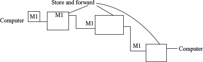
Figure 9.17 Message switching
9.5.1.3 Packet Switching
- Like message switching, packet switching does not establish a physical path between the sender and the receiver, in advance. Packet switching (Figure 9.18) also uses the ‘store and forward’ mechanism. However, instead of a complete message, packets are sent over the network. Packet switching splits a message into small “packets” of defined size to be sent over the network. Each packet is numbered.
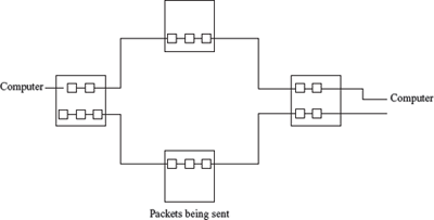
Figure 9.18 Packet switching
- A packet is a self-contained part of data that can be sent over the network. A packet contains the data to be transmitted and a header that contains information about the packet, like the source and destination addresses, size of packet, error checking bytes etc.
- Since the path through which the packets travel is not reserved, the packets may travel through different paths in the network and may not reach the destination in order. At the destination, the received packets are reassembled (according to the packet number), and the complete message is constructed.
- Packet switching is suited for interactive traffic. Packet switching limits the size of the packet and does not block a network node for a long time. Moreover, a node can transmit a packet before the arrival of another full packet, thus reducing the delay.
- Packet switching does not require dedicated communication link, and shares the underlying resources. Packet switching is commonly used for computer networks, including the Internet.
9.6 COMPUTER NETWORK
A computer network is an interconnection of two or more computers that are able to exchange information. The computers may be connected via any data communication link, like copper wires, optical fibers, communication satellites, or radio links. The computers connected to the network may be personal computers or large main frames. The computers in a network may be located in a room, building, city, country, or anywhere in the world.
9.6.1 Network Types
Computer network is broadly classified into three types—(1) Local Area Network (LAN), (2) Metropolitan Area Network (MAN), and (3) Wide Area Network (WAN). The different network types are distinguished from each other based on the following characteristics:
- Size of the network
- Transmission Technology
- Networking Topology
The size ofthe network refers to the area over which the network is spread. Transmission technology refers to the transmission media used to connect computers on the network and the transmission protocols used for connecting. Network topology refers to the arrangement of computers on the network or the shape of the network. The following subsections discuss the three types of networks and their characteristics.
9.6.1.1 Local Area Network
LAN (Figure 9.19) is a computer network widely used for local communication. LAN connects computers in a small area like a room, building, office or a campus spread up to a few kilometers. They are privately owned networks, with a purpose to share resources and to exchange information.
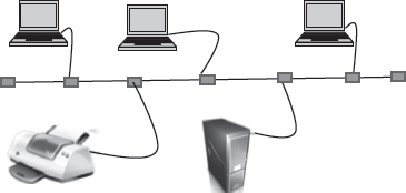
Figure 9.19 LAN
The computers in a LAN are generally connected using cables. LAN is different from other types of network since they share the network. The different computers connected to a LAN take turns to send data packets over the cables connecting them. This requires coordination of the use of the network. Some of the transmission protocols used in LAN are Ethernet, Token bus, and FDDI ring.
Star, Bus, and Ring are some of the common LAN networking topologies. LAN runs at a speed of 10 Mbps to 100 Mbps and has low delays. A LAN based on WiFi wireless network technology is called Wireless Local Area Network (WLAN).
9.6.1.2 Metropolitan Area Network
MAN (Figure 9.20) is a computer network spread over a city. Cable television network is an example of MAN. The computers in a MAN are connected using coaxial cables or fiber optic cables. MAN also connects several LAN spread over a city.
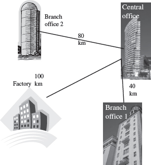
Figure 9.20 MAN
9.6.1.3 Wide Area Network
WAN is a network that connects computers over long distances like cities, countries, continents, or worldwide (Figure 9.21). WAN uses public, leased, or private communication links to spread over long distances. WAN uses telephone lines, satellite link, and radio link to connect. The need to be able to connect any number of computers at any number of sites, results in WAN technologies to be different from the LAN technologies. WAN network must be able to grow itself. Internet is a common example of WAN.
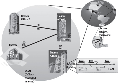
Figure 9.21 LAN, MAN and WAN
9.6.2 LAN Topologies
There are different types of network topologies that are used in a network. The network topologies in the structure or the layout of the different devices and computers connected to the network. The topologies commonly used in LAN are—Bus topology, Star topology, and Ring topology.
9.6.2.1 Bus Topology
- All devices on the network are connected through a central cable called a Bus (Figure 9.22).

Figure 9.22 Bus topology
- The data signal is available to all computers connected to the bus .
- The data signal carries the address of the destination computer.
- Each computer on the network checks the destination address as the data signal travels through the bus. The computer whose address matches makes a copy of the signal and converts it into data. The data signal on the bus does not get destroyed and still transmits along the bus, and is finally absorbed by the terminator attached to the end of the network.
- It is good for connecting 15–20 computers.
- A single coaxial cable is generally used in bus topology, to which the computers or devices are connected.
- Ethernet is a commonly used protocol in networks connected by bus topology.
9.6.2.2 Ring Topology
- All devices in the network are connected in the form of a ring.
- Each device has a receiver and transmitter to receive the data signals and to send them to the next computer, respectively.
- Ring network does not have terminated ends, thus data signals travel in a circle.
- Ring topology (Figure 9.23) uses token passing method to provide access to the devices in the network.
- The computers or devices are connected to the ring using twisted pair cables, coaxial cables or optic fibers.
- The protocols used to implement ring topology are Token Ring and Fiber Distributed Data Interface (FDDI).
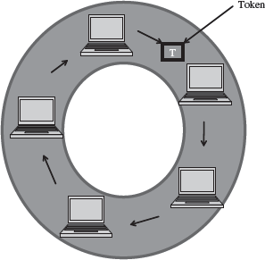
Figure 9.23 Ring topology
9.6.2.3 Star Topology
- All devices are connected through a central link forming a star-like structure.
- The central link is a hub or switch. The computers are connected to the hub or switch using twisted pair cables, coaxial cables or optic fibers.
- Star topology (Figure 9.24) is the most popular topology to connect computer and devices in network.
- The data signal is transmitted from the source computer to the destination computer via the hub or switch.
- The common protocols used in star topology are Ethernet, Token Ring, and LocalTalk.
In addition to the bus, ring, and star topologies, there are complex topologies like the tree topology, and the mesh topology used for networking in LAN. Table 9.1 lists the advantages and disadvantages of the different LAN network topologies.
9.6.3 Communication Protocol
Data networks are a combination of software and hardware components. The hardware includes transmission media, devices, and transmission equipments. The software allows the hardware to interact with one another and provide access to the network. The application programs that use the network do not interact with the hardware directly. The application programs interact with the protocol software, which follows the rules of the protocol while communicating. Protocol is a network term used to indicate the set of rules used by a network for communication.
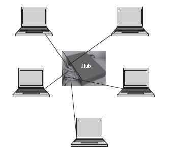
Figure 9.24 Star topology

Table 9.1 Advantages and disadvantages of network topologies
All the computers connected to the network use the protocol software. The network communication protocol is organized as a stack of layers with one layer built upon the other. Each layer has a specific function and interacts with the layers above and below it. The outgoing data from a computer connected to the network passes down through each layer and the incoming data passes up through each layer. The corresponding layers on the different machines are called peers. The peers interact with each other using the protocol.
The International Standards Organization (ISO) has developed a seven-layer reference model for data networks, known as Open System Interconnection (OSI) model. The OSI model specifies the functions of each layer. It does not specify how the protocol needs to be implemented. It is independent of the underlying architecture of the system and is thus an open system. The seven layers of the OSI model are—(1) Physical layer, (2) Data link layer, (3) Network layer, (4) Transport layer, (5) Session layer, (6) Presentation layer, and (7) Application layer. The functions of the different layers (Figure 9.25) are as follows:
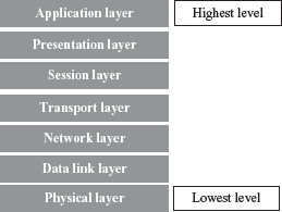
Figure 9.25 OSI model
- Physical Layer—This layer specifies the basic network hardware. Some of the characteristics defined in the specification are—interface between transmission media and device, encoding of bits, bit rate, error detection parameters, network topology, and the mode of transmission (duplex, half-duplex or simplex).
- Data Link Layer—This layer specifies the functions required for node-to-node transmission without errors. It specifies the organization of data into frames, error detection in frames during transmission, and how to transmit frames over a network.
- Network Layer—The network layer specifies the assignment of addresses (address structure, length of address etc.) to the packets and forwarding of packets to the destination i.e. routing.
- Transport Layer—It specifies the details to handle reliable transfer of data. It handles end-to-end error control and flow control, breaking up data into frames and reassembling the frames.
- Session Layer—The session layer maintains a session between the communicating devices. It includes specifications for password and authentication, and maintaining synchronization between the sender and the receiver.
- Presentation Layer—This layer specifies the presentation and representation of data. Its functions include translation of the representation of the data into an identifiable format at the receiver end, encryption, and decryption of data etc.
- Application Layer—This layer specifies how an application uses a network. It deals with the services attached to the data. It contains the protocols used by users like HTTP, protocol for file transfer and electronic mail.
Each layer at the sender’s side transforms the data according to the function it handles. For this it attaches headers to the data. At the receiver’s side, the corresponding layer applies the inverse of the transformation that has been applied at the source (Figure 9.26). As an example, if the Data link layer at the sender’s side adds an error detection code to the frame, then at the receiver’s side, the Data link layer verifies the error detection code and removes it from the frame before passing it to the next higher level, i.e. the Network layer.

Figure 9.26 Data transfer in OSI model
The 7-layer ISO reference model forms a framework for communication between the devices attached to the network. For different networks, the number of layers and their functions may vary. For example, the TCP/IP Internet protocol is organized into five layers. The X.25 Wide Area Network protocol (the first public data network) provides connectivity to Public Switched Telephone Network (PSTN) network and has three layers.
9.6.4 Network Devices
The cables are used to transmit data in the form of signals from one computer to another. But cables cannot transmit signals beyond a particular distance. Moreover there is a need to connect multiple computers and devices. A concentrator is a device having two or more ports to which the computers and other devices can be connected. A concentrator has two main functions—(1) it amplifies the signal to restore the original strength of the signal, and (2) it provides an interface to connect multiple computers and devices in a network. Repeater, hub, switch, bridge, and gateway are examples of network connecting devices.
Two or more LANs using different protocols may not be able to communicate with the computers attached to their network. For example, a LAN connected using Ethernet may not be able to communicate with a LAN connected using Token Ring. Bridge, Router, and Gateway are devices used to interconnect LANs.
9.6.4.1 Network Interface Card
- A Network Interface Card (NIC) is a hardware device through which the computer connects to a network.
- NIC is an expansion card (Figure 9.27), it can be either ISA or PCI, or can be on-board integrated on a chipset. NIC has an appropriate connector to connect the cable to it. NIC for different LAN are different (NIC for token ring is different from NIC for Ethernet).

Figure 9.27 NIC card
- NIC work at both the data link layer and physical layer of the OSI reference model.
- At the data link layer, NIC converts the data packets into data frames, adds the Media ACcess address (MAC address) to data frames. At the physical layer, it converts the data into signals and transmits it across the communication medium. The MAC address is a globally unique hardware number present on the NIC and is specified by the NIC manufacturer.
- NIC depends upon the configuration of the computer, unlike hub or switches that perform independently.
9.6.4.2 Repeater
- Repeaters (Figure 9.28) are used to extend LAN. It has only two ports and can connect only two segments of a network. Multiple repeaters can be used to connect more segments. (Segment is a logical section of the same network).

Figure 9.28 Repeater
- Repeaters operate at the Physical layer of OSI reference model.
- They are useful when computers in a network are located far away from each other.
- Repeaters amplify the signal so that the signal is as strong as the original signal. They can thus extend the reach of a network.
- Repeaters cannot be used if multiple computers need to be interconnected or multiple segments need to be interconnected.
- Repeaters cannot identify complete frames. Thus, in addition to the valid transmissions from one segment to another, repeater also propagates any electrical interference occurring on a segment to other segment.
9.6.4.3 Bridge
- Bridge (Figure 9.29) is used to connect two LAN segments like a repeater; it forwards complete and correct frames to the other segment. It does not forward any electrical interference signals to the other segment.
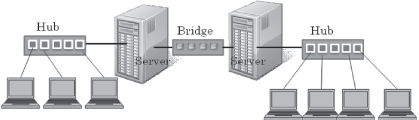
Figure 9.29 Bridge
- Bridge forwards a copy of the frame to the other segment, only if necessary. If a frame is meant for a computer on the same segment, then bridge does not forward a copy of the frame to other segment.
- Bridge connects networks that use different protocol at the Data Link Layer. The frame format of data in the two networks is different. The bridge converts the frame format before transmitting data from one network to another, with translation software included in the bridge.
- A bridge is also used to divide a network into separate broadcast domains to reduce network traffic while maintaining connectivity between the computers.
9.6.4.4 Hub
- It is like a repeater with multiple ports. But, hub does not amplify the incoming signal.
- Hub (Figure 9.30) operates at the Physical layer of OSI reference model, hence treats data as a signal.

Figure 9.30 Hub
- Hubs are used to connect multiple segments of the same network.
- Hubs are also used to connect computers to network that use Star topology.
- The port on the hubs can also be used to connect another hub, switch, bridge or router.
- Hubs increase the network traffic because they broadcast data to all the device connected all the ports of the hub.
- It is preferable to use a hub in a small LAN having about 8–10 computers connected to it.
9.6.4.5 Switch
- Like hub, switch also connects multiple computers in a network or different segments of the same network. A hub simulates a single segment that is shared by all computers attached to it (hub transmits the data to all computers attached to it). In a hub, at most two computers can interact with each other at a given point of time. However, in a switch each computer attached to a switch has a simulated LAN segment.
- Switches (Figure 9.31) work at the Data Link Layer of the OSI reference model.Hence, switches consider data as frames and not as signals.
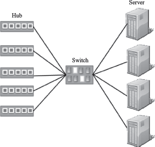
Figure 9.31 Switch
- A data frame contains the MAC address of the destination computer. A switch receives a signal as a data frame from a source computer on a port, checks the MAC address of the frame, forwards the frame to the port connected to the destination computer having the same MAC addresses, reconverts the frame back into signal and sends to the destination computer. (Switching is a technique that reads the MAC address of the data frame and forwards the data to the appropriate port). Switches, thus, regenerate the signals.
- Since a switch does not broadcast data, but sends the data from the source computer to the destination computer, a half of the computers attached to the switch can send data at the same time.
- Switch is also referred to as a multi-port bridge. In general, bridges are used to extend the distance of the network, and switches are primarily used for their filtering capabilities to create a multiple and smaller virtual LAN (a LAN segment can be connected to each port of the switch) from a single large LAN.
9.6.4.6 Router
- Router (Figure 9.32) is used to connect heterogeneous networks.
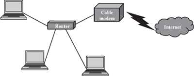
Figure 9.32 Router
- A router has a processor, memory, and I/O interface for each network to which it connects.
- A router connects networks that use different technologies, different media, and physical addressing schemes or frame formats.
- A router can connect two LANs, a LAN and a WAN, or two WANs.
- A router is used to interconnect the networks in the Internet.
- Router operates at the Network layer of the OSI model (layer 3).
- Physically, a router resembles a bridge, but is different from a bridge. A router determines which way is the shortest or fastest in a network, and routes packets accordingly. Since it works at the Network layer, it moves packets based on the IP addresses etc. In contrast, a bridge connects two LANs almost permanently.
9.6.4.7 Gateway
- Gateway (Figure 9.33) is a generic term used to represent devices that connect two dissimilar networks.
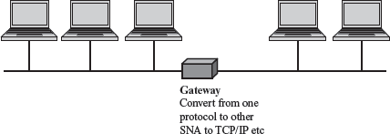
Figure 9.33 Gateway
- A gateway at the transport layer converts protocols among communications networks. It can accept a packet formatted for one protocol and convert it to a packet formatted for another protocol, before forwarding it. An application gateway can translate messages from one format to the other.
- A gateway can be implemented in hardware, software, or in both hardware and software. Generally, gateway is implemented by software installed within a router.
The network connecting devices—repeater and hub operate at the physical layer, bridge and switch operate at the data link layer, and the router operates at the network layer of the OSI model.
9.7 WIRELESS NETWORKING
Wireless technology, as the name suggests, is used to establish a wire-free connection or communication between two or more devices. In contrast to the wired technology where data is encoded as electric current and signals travel through wires, in wireless technology data is encoded on electromagnetic waves that travel through air. The wireless technology is used for broadcasting in radio and television communication, for communication using mobile phones and pagers, for connecting components of computers using Bluetooth technology, for Internet connection using Wi-Fi, Wireless LAN, PDA, and in remote controls for television, doors etc.
- Wireless network is a computer network connected wirelessly. The communication is done through a wireless media like radio waves, infrared or Bluetooth.
- The wireless networks have two main components—the wireless access points that include the transmitter along with the area it can cover, and the wireless clients like mobile handsets, laptops with Ethernet cards etc.
- The access point receives data frames from the computers attached to it wirelessly, checks the frames, and transmits them to their destination. The coverage area of a transmitter depends on the output power of the transmitter, its location, and the frequency used to transmit the data. Higher frequencies require a clear line of sight as compared to lower frequencies.
- The speed of wireless connection is determined by the distance of the wireless client device from the access point, the obstruction-free path (walls, trees etc.), interference, and the number of users using the network at a given time.
- Wireless networks can be divided into three categories based on their use:
- Bluetooth technology to connect the different components of the computer in a room, a small office or home.
- Wireless LAN is used to connect computers and devices wirelessly in a LAN, for example, different computers or devices in an office or campus.
- Wireless WAN is used to connect wide area systems, for example access to Internet via mobile devices like cell phone, PDAs and laptops.
9.7.1 Bluetooth Technology
The different components of the computer like the keyboard, printer, monitor etc., are connected to the computer case via wires. Bluetooth technology (Figure 9.34) is used to connect the different components wirelessly. A printer placed in a room may be connected to a computer placed in a different room using Bluetooth technology. Using Bluetooth does away with the wires required to connect the components to the computer and allows portability of components within a small area lying within the Bluetooth range.

Figure 9.34 Bluetooth
9.7.2 Wireless LAN
Wireless LAN (Figure 9.35) has some benefits over the wired LANs. In wireless LAN, there is flexibility to move the computers and devices within the network. It can connect computers where cabling is not possible. It is easy to expand by using an access point. Since no physical medium is required, wireless LANs are easy to install. Since data is transmitted using radio or infrared waves, there is no attenuation or distortion of the signal due to electromagnetic interference. Wireless LANs are used at home to connect devices on different floors or to set up a home network (Figure 9.36), to provide connectivity in public places like airports, railway stations, college campus, and hotels etc., where traveling users can access the network. Wireless LANs can also be connected to a WAN thus providing access to Internet to the user. IEEE 802.11 is a standard for wireless LAN.
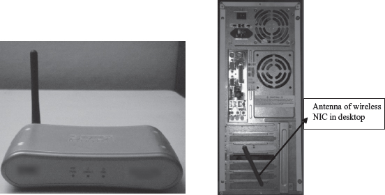
Figure 9.35 (a) Wireless ethernet bridge (b) Wireless antenna in a desktop

Figure 9.36 Computers at different floors in a house connected by wireless LAN
9.7.3 Wireless WAN
The radio network used for cellular telephone is an example of wireless WAN (Figure 9.37). Wireless WANs allow the users to access the Internet via their mobile devices. This provides flexibility to the user to access the Internet from any location where wireless connectivity exists.

Figure 9.37 Wireless WAN
Almost all wireless networks are connected to the wired network at the back-end to provide access to Internet. Wireless networks also offer many challenges, like, the compatibility among different standards promoted by different companies, congested networks in case of low bandwidth, the high infrastructure and service cost, data security, battery storage capability of wireless device, and health risk.
SUMMARY
- Networking of computers facilitates resource sharing, sharing of information, and, can be used as a communication medium, and for backup and support.
- The transmission ofdata can be via guided media like twisted pair, coaxial pair, optical fibers or as radio transmission, microwave transmission, and satellite transmission.
- A twistedpair cable consists of four pairs of twisted copper wires. STP and UTP are the two kinds of twisted pair.
- Coaxial cable has an inner conductor that transmits electric signals and an outer conductor as a ground. Optical fibers transmit data over large distances. They use light signals.
- Simplex, half-duplex and full-duplex are three modes of data transmission. Simplex is uni-directional, halfduplex is bi-directional but one device sends data and other receives it, and, full-duplex is bi-directional and both the devices can send and receive data at the same time.
- Bandwidth is the amount of data that can be transferred through the communication medium, in a fixed amount of time. Bandwidth is measured in Hz.
- Throughput is the amount of data that is actually transmitted between two computers. It is specified in bps. Throughput is affected by the distance between the connected computers.
- Analog and digital signals are the two types of signals that are used for carrying information over a transmission medium.
- Modulation is the superimposing of signal carrying data onto the carrier wave. Demodulation is segregation of data signal and carrier signal from the modulated carrier wave.
- Modem is a device that has both a modulator and a demodulator.
- The combining of multiple signals so that they can be transmitted over a single link of communication medium is called multiplexing.
- Switching allows different users fair access to the computer network. Packet Switching, Circuit Switching, and Message Switching are the three kinds of switching techniques.
- In PacketSwitching, the message is broken into small packets and sent over the network. At destination, the received packets are reassembled and the complete message is constructed.
- Computer Network is interconnection of two or more computers that can exchange data.
- LAN, MAN, and WAN are the network types classified on the basis of the size of network, the transmission technology, and the network topology.
- Bus, Star, and Ring are the three common LAN topologies.
- The computers are connected to network via protocol software.OSI model is a seven-layer reference model for data networks.
- Network connecting devices are required to amplify the signal to restore the original strength of signal, and to provide an interface to connect multiple computers in a network. Repeater, hub, switch, bridge, router, and gateway are network connecting devices.
- Repeaters have two ports and can connect two segments of a LAN. Repeaters amplify the signal so that the signal is as strong as the original signal.
- Bridge connects two LAN segments and forwards correct frames to the other segment.
- Hub is like a repeater with multiple ports. Hub does not amplify the incoming signal.
- In a switch, each computer attached to it is a simulated LAN segment.
- Router connects networks that use different technologies, different media, and physical addressing schemes or frame formats.
- Gateway is a generic term used to represent devices that connect two dissimilar networks.
- Wireless network is a computer network connected wirelessly. Bluetooth, wireless LAN, and wireless WAN are the three categories of wireless networks.
KEYWORDS
10 base 2 |
Electromagnetic signal |
Packet |
10 base 5 |
Frequency Division Multiplexing |
Packet switching |
Amplitude Modulation |
(FDM) |
Phase shift Modulation |
Analog signal |
Frequency Modulation |
Radio Frequency (RF) |
Asynchronous communication |
Full-duplex transmission |
transmission |
Attenuation |
Gateway |
Radio signal |
Bandwidth |
Geosynchronous satellites |
Repeater |
Baseband technology |
Guided media |
Ring topology |
bits per second (bps) |
Half-duplex transmission |
Router |
Bluetooth technology |
Hertz (Hz) |
Satellite Transmission |
Bridge |
Hub |
Shielded Twisted Pair (STP) |
Broadband technology |
LAN Topologies |
Signal |
Bus topology |
Light signal |
Simplex transmission |
Cat-5 cable |
Local Area Network (LAN) |
Star topology |
Circuit switching |
Message switching |
Switch |
Coaxial Pair |
Metropolitan Area Network |
Synchronous communication |
Computer network |
(MAN) |
Throughput |
Concentrator |
Microwave Transmission |
Twisted Pair |
Copper wire |
Modem |
Unshielded Twisted Pair |
cycles per second (cps) |
Modulation |
(UTP) |
Data Transmission Media |
Multiplexing |
Wavelength Division Multiplexing |
Demodulation |
Networking |
(WDM) |
Demultiplexing |
Network Interface Card |
Wide Area Network (WAN) |
Digital signal |
(NIC) |
Wireless LAN |
Distortion |
Optical fibers |
Wireless Networking |
Electric signal |
OSI model |
Wireless WAN |
QUESTIONS
Section 9.1–9.3.6
1. Explain the importance of networking.
2. “Networking allows sharing of information and resources”. Explain.
3. What do you mean by guided and unguided transmission media?
4. Name two guided transmission media.
5. Name an unguided transmission media.
6. Optical wire is a guided media. True or False.
7. _____ and _____ are the two kinds of twisted pair.
8. Cat-5 cable is a _____ twisted pair.
9. How is coaxial cable different from a twisted pair cable?
10. What are the features of a twisted pair cable?
11. What are the features of a coaxial cable?
12. List the advantages and disadvantages of optical wire over a copper wire.
13. Optical fiber transmits data as _____ signals.
14. Coaxial cables transmit data as _____ signals.
15. What are the features of an optical fiber?
16. Describe the following unguided transmission media—(i) RF transmission, (2) Microwave transmission, and (iii) Satellite transmission.
17. What are geosynchronous satellites?
Section 9.4–9.4.2
18. Define: (1) Simplex transmission, (2) Half-duplex transmission, and (3) Full-duplex transmission.
19. Define bandwidth.
20. Define throughput.
21. What is the unit of measuring bandwidth?
22. What is the unit of measuring throughput?
23. What do you mean by broadband technology?
24. ”The bandwidth or the throughput is affected by the distance between the connected computers”. Explain
25. Define attenuation.
26. Define distortion.
Section 9.4.3–9.4.3.4
27. Define a signal.
28. Which is better to use for data transmission—analog signal or digital signal? Why.
29. What is a carrier wave?
30. Why is modulation needed?
31. Explain modulation and demodulation.
32. What is the purpose of a modem?
33. Name the three kinds of modulation.
34. Define multiplexing and demultiplexing.
35. _____ and _____ are the basic multiplexing techniques.
36. What is the difference between the FDM and WDM multiplexing techniques?
37. Define synchronous and asynchronous transmission.
38. Give an example each of synchronous and asynchronous transmission.
Section 9.5
39. Name the three kinds of switching techniques.
40. Describe briefly the circuit switching and message switching techniques.
41. Define a packet.
42. Which switching technique is most commonly used in computer networks? Why?
43. Explain the working of the packet switching technique.
Section 9.6–9.6.3
44. Define computer network.
45. Name the three types of networks classified on the basis of their size.
46. What do you mean by transmission technology?
47. What do you mean by network topology?
48. Describe briefly the LAN, MAN, and WAN transmission technologies.
49. Name three LAN topologies.
50. List the features of the following LAN topologies—(i) Bus, (ii) Star, and (iii) Ring.
51. Name the protocol(s) used to implement bus, ring and star technologies.
52. List the advantages and disadvantages of each of the LAN technology–Bus, Star, and Ring.
53. What is the need of communication protocol?
54. List the seven layers of the OSI model protocol, in order.
55. How does the OSI seven layer protocol work?
56. Describe briefly the function of each layer of the OSI model.
Section 9.6.4–9.6.4.7
57. Define a concentrator.
58. Name three network connecting devices.
59. What is the purpose of the Network Interface Card?
60. Describe the features of —(i) repeater, (ii) hub, (iii) switch, (iv) bridge, (v) router, and (vi) gateway.
61. Name a device used for connecting two LANs.
62. Name a device used for connecting computers in a LAN.
63. Name a device for connecting two WANs.
64. What is the purpose of a gateway?
65. Name a connecting device, each, that works at (i) physical layer, (ii) data link layer, and (iii) network layer.
Section 9.7
66. How is wireless networking different from wired networking.
67. Explain briefly how the wireless network works.
68. What is the use of Bluetooth technology?
69. _____ is a standard for wireless LAN.
70. What is the use of wireless LAN and wireless WAN.
Extra Questions
71. Give full form of the following abbreviations:
- STP
- UTP
- RF
- Hz
- bps
- cps
- FDM
- WDM
- LAN
- MAN
- WAN
- ISO
- OSI
- NIC
- MAC
- PSTN
- FDDI
72. Write short notes on:
- Importance of Networking
- Data transmission guided media
- Data transmission unguided media
- Twisted Pair
- Coaxial cable
- Optical Fiber
- Modulation and Demodulation
- Multiplexing
- Packet switching
- Network Types
- LAN topology
- Bus topology
- Ring topology
- Star topology
- OSI model
- NIC
- Hub
- Repeater
- Bridge
- Switch
- Router
- Wireless networking
73. Give differences between the following:
- Guided media and Unguided media
- STP and UTP
- Optical fibers and copper wires
- Bandwidth and Throughput
- Modulation and Demodulation
- Multiplexing and Demultiplexing
- Asynchronous and Synchronous Transmission
- Message switching and Packet switching
- Bus, Ring and Star LAN topologies
- Repeater and Bridge
- Hub and Switch
- Router and Bridge