
7
CHEMISTRY OF ENGINEERING MATERIALS
7.1 SEMICONDUCTING AND SUPER CONDUCTING MATERIALS
According to conductivity, elements or materials are broadly classified into three categories. They are as follows:
- Conductors
- Semiconductors
- Insulators
Conductors
They allow the maximum portion of the applied thermal or electric field to flow through them.
For example, metals are good conductors.
Insulators
They do not practically allow the heat or electricity to flow through them.
For example, most organic and inorganic solids, except graphite.
Semiconductors
The thermal and electrical conductivity of a semiconductor at normal temperature lies between that of a conductor and an insulator.
Semiconductors are those solids which are perfect insulators at absolute zero, but conduct electric current at room temperature. For example, silicon and germanium are two important elements used as semiconductors.
7.1.1 Semiconductor
At room temperature, semiconductors allow a portion of electric current to flow through them. The electrical conductivity of a semiconductor at normal temperature lies between that of a good conductor and an insulator in the range of 10-9 to 102 ohm-1cm-1.
Semiconductors are those solids which are perfect insulators at absolute zero, but conduct electric current at room temperature. Silicon and germanium are two very important elements used as semiconductors. The pure samples (≥99.999% pure) of these elements are obtained by zone refining; some impurity is added deliberately to these elements by a process called doping. These are of two types—intrinsic and extrinsic.
Intrinsic Semiconductors (Semiconductors Due to Thermal Defects)
Pure silicon or germanium act as insulators because electrons are fixed in covalent bonds and are not available for conduction. At high temperatures, electrons are released by breaking of some of the covalent bonds. These electrons move freely in the crystal and can conduct electricity. Without introducing an external substance, these materials show conduction. Hence, these materials are known as intrinsic semiconductors.
Extrinsic Semiconductors (Semiconductors Due to Impurity Defects)
Silicon and germanium (group 14 elements) in pure state have very low electrical conductivity. However, the low electrical conductivity of these elements is greatly enhanced by the addition of even traces of an element belonging to groups 13 (iii) or group 15 (v) to the crystals of group 14 (iv) elements, that is, silicon or germanium. The induction of group 15 and group 13 elements to the crystal lattice of group 14 elements (Si or Ge) produces n-type semiconductors and p-type semiconductors respectively.
n-type Semiconductors (n Stands for Negative)
This type of semiconductor is produced in any of the following ways:
- Due to metal excess defect (explained earlier)
- By the addition of trace amount of group 15 element (P, As) to extremely pure germanium or silicon by a process called doping.
When an element of group 15(As) is added to germanium (group 14 element) crystal, some atoms of germanium are replaced by arsenic. In such cases, four electrons of the impurity element (As) are used in forming bonds to Ge, while the fifth electron remains unused. The additional electrons can move freely and conduct electricity in the metals.
Hence, arsenic-doped germanium exhibits fairly high electrical conductivity.
p-type Semiconductor (p Stands for Positive)
This type of semiconductors are formed by the following ways:
- Due to metal deficiency defects
- By addition of impurity atoms containing less electrons (i.e., atoms of group 13); in such cases, the parent insulator to the insulator lattice behaves like a conductor–electron.
When a group 13 element (like B, Ga, In) substitutes for a germanium atom (group 14 element), that is, when a group 13 element (say B, having only three electrons in the outer shell) is added in small traces to group 14 elements (say germanium), the atoms of B are not able to complete tetrahedral covalent structures because they have one electron short of the requirement. Hence, some of the sites normally occupied by electrons will be left empty. This gives rise to electron vacancies, commonly known as positive holes because the net charge at these sites is positive. With an electric field, the adjacent electrons move into the positive holes and form other positive holes. The current is passed in the crystal due to the migration of positive holes. The electrical conductivity of germanium (group 14 element) crystal increases by the doping trace amount of B (group 13 element). Here, the current is carried by positive holes; hence, this type of conduction is known as p-type semi conduction.
Unlike metals, the conductivity of semiconductors increases with increase in temperature. This is due to the fact that an extra electron or a positive hole is weakly bound with the crystal; when energy is supplied in the form of heat, they (electron or a positive hole) become force from the crystal lattice for the conduction of electricity.
7.1.2 Applications of Semiconductors
Various semiconductors have been prepared by the following types of combination.
- Elements of group 14 (Se, Ge) and group 15 (P, As, Sb)
- Elements of group 13 (B, Ga) and group 14 (Si, Ge)
- Elements of group 13 and group 15 (In Sb, Al, P)
- Elements of group 12 and group 16 (ZnS, CdS, CdSe, Hg, Te)
The properties of a semiconductor are considerably changed depending upon the nature of the impurity. Semiconductors are used in transistors and in exposure metals as photoelectric devices. A combination of p- and n-type of semiconductors (known as p-n junction) allows electric current from outside to flow through it in one direction. This type of p-n junction is known as a rectifier and is used for converting alternating current to direct current.
7.1.3 Superconductors
The electrical resistance of metals depends upon temperature. The electrical resistance decreases with a decrease in temperature and becomes almost zero near the absolute temperature. Materials in this state are said to possess super-conductivity. Thus, super-conductivity may be defined as a phenomenon in which metals, alloys and chemical compounds become perfect conductors with zero resistivity at temperatures approaching absolute zero. Super-conductors are diamagnetic. The phenomenon was first discovered by Kamerlingh Onnes in 1913 when he found that mercury becomes super-conductor at 4K. The temperature at which a substance behaves as super-conductor is called transition temperature. Most metals exhibit this phenomenon at a temperature range of 2K and 5K.
Efforts are being made to find materials that behave as super-conductors at room temperature because attaining low temperature with liquid helium is highly expensive. The highest temperature at which super-conductivity has been observed is 23K for alloys of niobium (Nb3Ge). Since 1987, many complex metal oxides have been found to possess super-conductivity at fairly high temperatures. Some examples are given here.

Super-conductors have many application in electronics, building magnets, aviation transportation (trains which move in air without rails) and power transmission.
7.2 MAGNETIC MATERIALS
Magnetism is the ability of matter in which there is a force of attraction or repulsion between unlike or like poles. More than 2,000 years ago, ancient Greeks discovered a mineral that attracts things made of iron. This mineral was found in Magnesia, a part of Turkey; hence it was named magnetite. Magnets are commonly used in workplaces and homes.
7.2.1 General Properties of Magnetic Materials
Some of the properties of magnetic materials are as follows:
- The Earth acts as a big bar magnet through its core. The north pole of magnets and compass needles point to the Earth’s magnetic south pole, which is near the Earth’s geographic north pole.
- All magnets have two poles. If a magnet is allowed to rotate freely, the north pole will always point to the north and the other is called the south pole.
- Opposite magnetic poles attract each other and like magnetic poles repel.
- Every magnet is surrounded by a magnetic field. The magnetic field lines explain the shape of the field.
- According to Becquerel and Faraday, all matter including liquids and gases were affected by magnetism, but a few respond to a noticeable extent and others do not.
7.2.2 Classification of Magnetic Materials
According to Faraday’s law of magnetic induction, the magnetic forces of material electrons will be affected when a material is placed within a magnetic field. However, in a magnetic field material, electrons can react quite differently (attract/repel). This mainly depends on the atomic or molecular structure of the material and the net magnetic field associated with the atom. Depending on the attraction and repulsion in the magnetic field, materials can be classified into five categories as follows.
- Diamagnetic materials—weak repulsion to field
- Paramagnetic materials—weak attraction to field
- Ferromagnetic materials—strong attraction to field
- Ferrimagnetic materials—strong attraction to field
- Antiferromagnetic materials—no magnetic moment
Diamagnetic Materials
Diamagnetic materials have weak magnetic susceptibility; hence, they repel slightly in a magnetic field and the material does not retain the magnetic properties when the external field is removed. Such materials have no permanent net magnetic movement due to paired electrons. In the external magnetic field, the electron paths are realigned; hence, the material shows weak repulsion. For example, copper, silver, gold, etc.
Paramagnetic Materials
Paramagnetic materials have a small positive susceptibility; hence, they attract slightly in a magnetic field and the material does not retain the magnetic properties when the external field is removed. Due to the presence of some unpaired electrons and the realignment of the electron path with the external magnetic field, the materials show paramagnetism.
For example, magnesium, molybdenum, lithium, tantalum, etc.
Ferromagnetic Materials
Ferromagnetic materials have large positive susceptibility; hence, they exhibit strong attraction to magnetic field and the materials retain their magnetic properties after the external field has been removed due to the presence of magnetic domains. Due to the presence of unpaired electrons, ferromagnetic materials have net magnetic moment. Here, all the magnetic dipoles are aligned parallel and are oriented in the same direction. For example, iron, nickel, cobalt, etc.
Curie Temperature
At a particular temperature, the electronic exchange forces in ferromagnets are very large. Hence, thermal energy eventually overcomes the exchange and produces a randomising effect, and that temperature is known as “Curie temperature”. Below the Curie temperature, the ferromagnet is ordered and the above is disordered.
Hysteresis
Retaining magnetic properties after the removal of external magnetic field is known as hysteresis.
Magnetic Domain
In ferro and ferrimagnetic materials below Curie temperature, a large number of atom moments is aligned parallel as small volume regions. This is known as “domain”. The adjacent domains are separated by boundaries and are shown in Figure 7.1.

Figure 7.1 Adjacent domains separated by boundaries
Ferrimagnetic Materials
Ferrimagnetism is similar to ferromagnetism, but is observed in complex crystals and not in atoms in which the magnetic moments of neighbouring ions are antiparallel and unequal in magnitude.
For example, magnatite was considered a ferromagnet until 1940. In 1940, Neel provided the theoretical framework about ferrimagnetism.
Antiferromagnetic Materials
Antiferromagnetism is a phenomenon exhibited by materials in which the complete magnetic movement is cancelled with the antiparallel coupling of adjacent atoms or ions. Here, the successive magnetic dipoles are aligned in opposite directions with the same magnitude; hence, it has no net magnetic moment.
For example, manganous oxide, chromium, etc.
Magnetic materials and their spin alignment are shown in Figure 7.2.

Figure 7.2 Magnetic materials and spin alignment
7.2.3 Applications of Magnetic Materials
Magnets are used in a vast array of products from loudspeakers to space research. Some applications are as follows:
- Power conversion (electrical to mechanical): In motors (starter motor, power steering motors, washer pumps), generators and electromagnets.
- Power adaptation and signal transfer: Transformers.
- Permanent magnets: Loudspeaker, sensors, navigation and information systems.
- Data storage analogue: Video and audio tapes.
- Data storage digital: Hard disk, floppy disk.
- Quantum devices: Magnetoresisstive random access memory (MRAM), Gaint magnetoresistance (GMR) reading head.
- Instrumentation: Dashboard instruments, nanoscience and technology, medicine, research, etc.
7.3 CEMENT
Concrete is a widely used non-metallic material in construction. Cement is an important bonding material and can bond sand and rock with water in concrete. It has adhesive and cohesive nature and can bond with bricks, stones, etc.
7.3.1 Classification of Cement
Cement is broadly classified into natural, puzzolana, slag and Portland cement. These are briefly discussed here.
Natural Cement
Natural cement is prepared with the calcination and pulverisation of naturally occurring argillaceous limestone at high temperature. During calcination, calcium silicates and aluminates are formed.
Natural cement is a setting cement and possesses hydraulic qualities and relatively low strength.
The combination of sand with natural cement is known as mortar and is used in laying bricks and setting stones. Mortar is also used in the construction of dams and as a foundation for bulk masses of concrete.
Puzzolana Cement
Puzzolana cement is the oldest cement. It is invented by Romans and is used by them for the construction of walls and domes.
The mixing and grinding of natural puzzolana and slaked lime gives puzzolana cement. Volcanic ash produced by rapid cooling of lava is known as natural puzzolana. It is a molten mixture of silicates of calcium, aluminium and iron and has hydraulic properties as well.
Slag Cement
Slag cement is a mixture of lime and blast furnace slag. A mixture of calcium and aluminium silicates (blast furnace slag) is granulated by pouring into a stream of cold water, dried mixed with hydrated lime and pulverised to fine powder. The setting of slag cement is too slow, poor in abrasion resistance and lower in strength. Hence, slag cement has limited applications and is used for making concrete in bulk construction.
Portland Cement
In 1824, William Aspdin prepared Portland cement by heating limestone and clay by crushing the resulting product to a fine powder. Hence, he is known as father of Portland cement. On mixing with water, the cement is set to give a hard stone-like mass and resembles the stone of Portland, England. Hence, it is known as a magic powder.
7.3.2 Raw Materials used in the Manufacture of Portland Cement
Portland cement primarily consists of lime, silica, alumina and iron.
The following materials are used for manufacture of cement:
- Calcareous materials, CaO (such as limestone, chalk, marl, etc.)
- Argillaceous materials, Al2O3 (such as clay, shale, aluminium ore refuse, fly ash and so on)
- Siliceous material, SiO2 (such as clay, shale, sand and so on)
- Powdered coal or fuel oil
- Gypsum (CaSO4 · 2H2O) and
- Iron components, Fe2O3 (ferriferous materials such as clay, iron ore and so on)
Importance and the Effects of the Ingredients on Cement
The proportion of the ingredients should be properly maintained; otherwise, the following effects may be observed on the characteristics of cement.
Strength: Lime, silica, iron oxide and alumina play a vital role on strength of the cement. However, excess/loss amount of lime and alumina reduces the strength due to expansion and disintegration.
Colour and hardness: Iron oxide provides colour and hardness to cement.
Soundness: A small amount of sulphur trioxide imparts soundness to cement; however, excess amount reduces the soundness.
Setting: Alumina and lime help in quick setting. Gypsum helps to retard the setting action of cement and enhances the initial setting time.
Efflorescent: Excess alkali causes the efflorescent.
7.3.3 Manufacture of Portland Cement
The manufacture of Portland cement involves the following steps:
- Crushing
- Mixing
- Burning
- Grinding
- Packing
Crushing
Crushing of raw materials is done with two crushers. The primary crusher reduces the size of the raw material to approximately five inches and the secondary crusher further reduces the size to three-fourth inches. These are then ground to a fine powder (in ball mills or tube mills). Each separate powdered ingredient is stored in separate hoopers (Figure 7.3).

Figure 7.3 Stone being reduced to five inches and three-fourths and stored
Mixing
Mixing of raw materials can be done either by a dry or a wet process.
Dry Process
The following proportions of the powdered materials, that is, lime 60–69 per cent, silica 17–25 per cent, alumina 3–8 per cent, iron oxide 2–4 per cent, magnesium oxide 1–5 per cent, alkali oxides like Na2O + K2O 0.3–1.5 per cent and sulphur trioxide 1–3 per cent are then mixed and we get a raw mix. This is stored in silos (storage bins) and are sent to a rotary kiln for burning. This process is shown in Figure 7.4 (a) and (b).

Figure 7.4 (a) Dry process: mixing of raw materials; (b) Wet process: mixing of raw materials with water
Wet Process
The calcareous raw material is crushed, powdered, stored and the argillaceous material (clay) is thoroughly mixed with water for removing organic material in wash mills stored in basins. These two are led to grinding mills (tube mill/ball mill) through channels in the right proportions and are mixed to form a paste called slurry. The chemical composition of slurry may be adjusted with correcting basins, and it contains about 38–40 per cent of water and is stored in tanks for feeding to a rotary kiln.
Differences between dry and wet process of mixing raw materials shown in Table 7.1.
Table 7.1 Differences between dry and wet processes

Burning
The burning process is done in a rotary kiln containing a steel tube, lined inside with refractory bricks, having 2.5–3m in diameter and 90–120m in length. The kiln is in a slightly inclined position and is capable of rotating at 1 rpm along its longitudinal axis. Fuel and air are injected at the lower end for burning, which produce long hot flames that heat the interior of the kiln up to 1,750°C.
From the upper end of the kiln, raw mix or corrected slurry is injected. From the lower end of the kiln, hot flames are forced with slow rotation and through slope of the kiln, the fed material move towards the bottom of the kiln and the material descends gradually with temperature.
Depending on the temperature, the kiln is divided into three zones. They are drying zone, calcination zone and clinkering zone.
Drying zone: It is the upper part of the kiln having temperature around 400°C. Here, water in the slurry gets evaporated.
Calcination zone: It is the central part of the kiln having temperature around 1,000°C. Here, limestone of the dry mix or slurry is decomposed to give quick lime as small lumps, also called modules and carbon dioxide, escape out.
![]()
Clinkering zone: It is the lower part of the kiln having temperature between 1500 and 1700°C. Here, the chemical interaction of fusion occurs between lime and clay to form calcium aluminates and silicates.

The silicates and aluminates of calcium fuse to form about 0.5–1cm diameter hard, greyish stones, known as clinkers. These are hot at about 1,000°C. They are cooled with cool air in another small rotary kiln at the base of the main kiln and are collected in small trolleys (Figure 7.5).

Figure 7.5 Burning changes raw mix chemically into cement clinker
Grinding
In ball mills or tube mills, the cooled clinkers are ground to fine powder and 2–3 per cent of gypsum is added to avoid quick setting and also acts as a retarding agent for early setting of cement, this is shown in Figure 7.6.
![]()

Figure 7.6 Grinding—clinker with gypsum added into Portland cement and shipped
After the initial set, the cement water paste becomes stiff, but gypsum retards the dissolution of C3A by forming tricalcium sulphoaluminate ![]() which is insoluble (Figure 7.6).
which is insoluble (Figure 7.6).
Thus,
![]()
The formation of insoluble C3A prevents very early further reactions of setting and hardening.
Packing
The ground cement is stored in silos, from which it is fed to automatic packing machines. Each bag, usually contains 50kg of cement.
The flow diagram for the manufacture of Portland cement is shown in Figure 7.7.
7.3.4 Chemical Composition of Portland Cement and its Importance
Portland cement mainly contains dicalcium silicate (C2S), tricalcium silicate (C3S), tricalcium aluminate (C3A) and tetracalcium alumina ferrite (C4AFe). Each component exhibits particular special behaviour, hence the behaviour of cement can be altered by changing the relative percentages of the aforementioned compounds.
Dicalcium Silicate (C2S)
Due to slow reaction with water, it gets hardened slowly and strengthens after one week with the formation of tobermonite gel with high surface area. Moist curing continues up to six months.
![]()

Figure 7.7 Flow diagram for the manufacture of Portland cement
Tricalcium Silicate (C3S)
This material is responsible for the initial setting and early strength by the formation of hydrolgel; it has a binding action between the aggregates when rapid reaction occurs with water.
![]()
Tricalcium Aluminate (C3A)
Due to fast hydration, this compound forms hydrated tricalcium aluminate and is responsible for the first few days of strength. This reaction is highly exothermic, hence cement is made with less C3A. At that time, it generates less heat, develops higher strengths and shows greater resistance to sulphate attacks.
![]()
Due to high heat generation and reactiveness with soil, C3A is the least preferred component in the cement.
Tetracalcium Aluminferrite (C4AF)
It hydrates very rapidly, reduces clinkering temperature and gives little strength to concrete.
![]()
Importance of Gypsum in Cement
Tricalcium aluminate (C3A) combines with water very rapidly with the evolution of large amount of heat (exothermic reaction).
![]()
After the initial set, the paste becomes almost stiff. However, in the presence of gypsum, it reacts with tricalcium aluminate to form insoluble tricalcium sulphoaluminate which helps to retard the speed of the initial set and does not show any tendency to rapid hydration.
![]()
The aforementioned reaction prevents high concentration of alumina in the cement solution and retards the early initial set of the cement.
7.3.5 Setting and Hardening of Cement
When water is added and mixed to cement to form cement paste, hydration begins and it is converted into gel and crystalline material. Solidification, interlocking and binding of the aggregates into a rock-like matter is two-step process in the form of setting and hardening.
Setting
It is the stiffening of the cement paste with the formation of gel setting that is divided into initial setting and final setting.
Initial setting: It refers to the hydration and gel formation from the different constituents of cement.

During the hydration of dicalcium, silicate gives tobermorite gel, which possesses very high surface area and a high adhesive property.
![]()
Final setting: It is the complete formation of tobermorite gel.
Hardening
Hardening is the development of strength with the crystallisation of calcium hydroxide and hydrated tricalcium aluminate.

Two theories are proposed for explaining the hardening of the cement.
Colloidal Theory by Michaels
According to this theory, silicate gels are formed with hydration and are responsible for hardening.
Crystalline Theory by Le Chatelier
According to this theory, crystalline products are formed with hydration, undergo interlocking and are responsible for hardening.
Hence, setting and hardening of cement is due to the interlocking crystallisation of gels, which are formed by hydrolysis of constitutional ingredients (Figure 7.8).

Figure 7.8 Schematic diagram of setting and hardening of cement
Ingredients and Reaction Sequence During Setting and Hardening of Cement
When water is added to cement, various ingredients undergo hydration and crystallisation in different rates (Figure 7.9).

Figure 7.9 Sequence of changes during setting and hardening of cement
7.3.6 ISI Specifications of Cement
According to ISI 269–1975, the composition of ordinary Portland cement shall satisfy the following conditions:
Chemical Requirement of Cement
- Ratio of the percentage of lime (CaO) to that of silica (SiO2), alumina (Al2O3) and iron oxide (Fe2O3) when calculated by the following formula:

- Ratio of percentage of alumina (Al2O3) to that of iron oxide (Fe2O3) shall not be less than 0.66.
- Weight of insoluble residue shall not exceed 2%.
- Weight of magnesia shall not be more than 6%.
- Total sulphur contents, calculated as sulphuric anhydride (SO3) shall not be more than 2.75%.
- Total loss on ignition shall not exceed 4%.
Physical Requirements of Cement
- Setting time:
Initial: not less than 30 minutes; final: not more than 600 minutes.
- Compressive strength (of 1:3 cement mortar cube of cement ampers; Ennore sand):
Three days—not less than 1.6 kg/mm2 (or 16 N/mm2)
Seven days—not less than 2.2 kg/mm2 (or 22 N/mm2)
- Soundness:
By Le Chatelier’s method, it expresses the expansivity of the cement set in 24 hours between 25°C and 100°C.
Unaerated cement—maximum 10 mm
Aerated cement—maximum 5 mm
- Fineness:
Not less than 215 m2/kg; finer the grinding, the greater is the rate of reactions, thereby hastening the early development of strength. However, finer cement generates heat quickly, thereby the cement mortar/concrete is likely to develop cracks.
7.3.7 Analysis of Cement
The quality of cement is maintained by conducting various tests from the raw material stage right up to the packing stage, at every half an hour to one hour intervals. In fact, various physical and chemical characteristics are tested. The quality of a sample of cement is determined from a number of measurements as follows.
Soundness: The soundness of cement can analysed by Le Chatelier technique and autoclave method. According to the ISI specifications, following properties should attain good quality of cement.
Soundness:
By auto clave method: Expansion not more than 0.8%
By Le Chatelier method:
For Aerated cement: maximum 5 mm
For Unaerated cement: maximum 100 mm
Fitness: By Turbidmetic method: 1600 cm2/gm.
By plain permeability method (as specific surface) ≥215 m2/kg.
Compressive strength: As per ISI specifications.
Tensile strength: As per ISI specifications.
Specific gravity: Specific gravity should be 3.1–3.2.
7.3.8 Plaster of Paris/Gypsum Plaster
Gypsum (hydrated calcium sulphate CaSO4 · 2H2O) is extensively used as a raw material for the manufacture of plates, which are almost universally used for coating the inner walls of dwellings.
It is the hemihydrate of calcium sulphate 2CaSO4 · H2O(or CaSO4 · ![]() H2O)
H2O)
Preparation
It is produced by heating pure gypsum to a temperature of about 120°C–160°C. If gypsum is heated above 200°C, anhydrous sulphate is produced, which loses the power of readily combining with water.

The preparation of plaster of Paris from gypsum consists of the following operations:
- Crushing and grinding of gypsum
- Calcination of ground gypsum in kilns by heating about 150°C
- Pulverising the calcined product
Setting and Hardening
Plaster of Paris forms a plastic mass when it is mixed with water. This plastic mass quickly sets or hardens, expanding in the process and regains the closely packed crystalline structure of gypsum. The setting of plaster of Paris can be accelerated by mixing it with alkali sulphates such as K2SO4, Na2SO4 or alums, which initiate as well as hasten the crystallisation process.
Applications
- Its slight expansion on setting renders plaster of Paris suitable for making mould. Therefore, some details are accurately reproduced.
- It is used in making surgical bandages, structural tiles and castings.
- It is used as plaster for walls and in plaster boards, made up of alternate layers of a fibrous material such as felt or paper.
7.4 REFRACTORIES
Refractories are ceramic materials that can withstand high temperatures as well as abrasive and corrosive actions of molten metals, slags and gases, without suffering a deformation in shape. The main objective of a refractory is to confine heat.
7.4.1 Characteristics of Good Refractory Materials
- A good refractory material should have excellent heat, corrosion and abrasion resistance.
- It should possess low thermal coefficient of expansion and should expand and contract uniformly with increase and decrease of temperature, respectively.
- It should possess high fusion temperature. It should be infusible at operating temperatures.
- It should be able to withstand the overlying load of structure, at operating temperatures.
- It should be chemically inert towards corrosive action of molten metal, gases and slags produced in its immediate contact with furnaces.
- It should not crack at operating temperatures.
7.4.2 Failures of Refractory Materials
If a given refractory material does not have the aforementioned characteristics, it will fail in service. Thus, we can easily summarise conditions, which lead to failure of refractory materials as follows:
- Refractory material which does not have resistance to required heat, corrosion and abrasion.
- Refractory material which has higher thermal expansion.
- Refractory material which has less refractoriness than the operating temperature.
- Lower quality refractory bricks than the actual load of raw materials in products.
- Usage of basic refractory material in a furnace in which acidic reactants and/or products are being processed and vice versa
- Refractory material that undergoes considerable volume changes during their use at high temperatures.
7.4.3 Classification of Refractories
On the basis of chemical properties, refractories are broadly classified into three main categories.
Acidic Refractories
Refractories which consist of acidic materials are known as acidic refractories.
They are easily attacked by basic materials and not by acidic materials.
For example, alumina, silica and fireclay refractories.
Basic Refractories
Refractories which consist of basic materials are known as basic refractories.There are easily attacked by acidic materials and not by basic materials.
For example, magnesite and dolomite.
Neutral Refractories
Refractories which consist of weak acidic/basic materials are known as neutral refractories. For example, zirconia, graphite, chromite and carborundum.
7.4.4 Properties of Refractories
The important properties of refractories are as follows.
Refractoriness
It is the ability of a material to withstand heat without appreciable deformation. It is commonly measured as the softening or melting temperature of the material. The softening temperatures of refractory materials are determined by using “pyrometric cones (seger cones) test” (Figure 7.10). The refractory should have a softening temperature much higher than the operating temperature of the furnace in which it is to be used.
Refractoriness is generally determined by comparing the behaviour of heat on the cone of the material to be tested with that of a series of seger cones of standard dimensions. Refractoriness is expressed in terms of pyrometric cone equivalent. Cones are 38mm height, 19mm long sides with triangular base pyramids, and at definite temperatures, they can melt or fuse. The temperature at the apex touching the base is indication of fusion/softening of the test cone. The number of the standard cones fusing along with the test cone is the pyrometric cone equivalent (PCE) of that particular refractory. If the test cone fuses later than one standard cone and earlier than the next cone, the PCE is the average value of the two.

Figure 7.10 Seger cone test
Porosity
Porosity is the property of a solid which contains openings, spaces or minute channels. It can be expressed as follows:
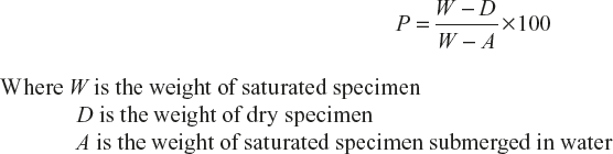

If the refractory has pores, the entry of gases, slags, etc., is easy and can react up to a greater depth. This can reduce the life of the refractory material. Consequently, it can affect many important properties of the refractory such as decreasing the strength, resistance to corrosion, resistance to abrasion but increased resistance to thermal spalling. Hence, a good refractory should have low porosity.
Strength or Refractoriness–under Load
The refractory material must possess high mechanical strength, even at operating temperatures to bear the maximum possible load, without breaking.
Dimension Stability
It is the resistance of a material to any volume changes, which may occur on its exposure to high temperature, over prolonged time. It may reversible or irreversible.
Chemical Inertness
A refractory does not easily form fusible products with gases, ash, slags, etc., and hence should be chemically inert.
Thermal Expansion
A refractory material should have the least possible thermal expansion due to the following reasons:
- Expansion of a refractory decreases the capacity of the furnace.
- Repeated expansion and contraction contribute much towards rapid breakdown and wear and tear of the material structure.
Thermal Conductivity
Depending upon the type of furnace refractory, materials of high and low thermal conductivity are required. In most cases, the furnace is lined with refractories of low-heat conductivities to reduce heat losses externally by radiation; otherwise, maintenance of high temperatures inside the furnace will become difficult. In muffle furnace walls and coke-oven batteries, a good heat conductivity of refractory is desirable for effective heat transmission.
Thermal Spalling
The breaking, cracking, peeling off or fracturing of a refractory brick or block under high temperature is known as thermal spalling.
Thermal spalling may be due to the following:
- Rapid change in temperature
- Slag penetration into the refractory brick
Thermal spalling can be decreased by taking the following precautions:
- Using high porosity, low coefficient of expansion and good thermal conductivity refractory bricks
- Avoiding sudden temperature changes
- By overfiring the refractories
- By modifying the furnace design
Heat Capacity
It depends on the following:
- Thermal conductivity
- Specific heat and
- Specific gravity of refractory
Resistance to Abrasion or Corrosion
Refractoriness is desirable that least abraded by descending hard charge, flue gases escaping at high speed, particles of carbon or grit, etc.
Electrical Conductivity
Refractories specially used for lining electric furnaces should have low electrical conductivity. Except graphite, all refractories are poor conductors.
Permeability
The rate of diffusion of gases, liquids and molten solids through a refractory is known as permeability.
It mainly depends on the size and number of connected pores. Permeability increases with temperature.
Texture
Due to large porosity, coarse- or light-textured bricks are less in weight; hence, they are more resistance to sudden temperature changes.
7.4.5 Manufacture of High-Alumina Bricks, Magnesite Bricks and Zirconia Bricks
High-alumina Bricks
High-alumina bricks are made by mixing calcined bauxite (Al2O3) with clay bind, which contains 50% or more of Al2O3.
Properties
High-alumina bricks have very low coefficient of expansion, high porosity, great resistance to slags, very little tendency to spall high temperature, load-bearing capacity, excellent wear-resistance and stability, both in oxidizing and reducing conditions and are particularly inert to the action of gasses such as CO2, H2 and natural gas. Thus, they are very good refractories, but very expensive; hence, their use is limited.
Uses
Medium-duty Bricks
Bricks which contain 50–60% Al2O3 are used for zones of vertical shaft kilns for burning limes, linings of Portland cement rotary kilns, soaking pits, reheating furnaces, hearths and walls, etc., and are subject to high abrasion.
High-duty Bricks
Bricks which contain 75% Al2O3 are used in sintering or the hottest zones of cement rotary kilns, lower parts of soaking pits, brass melting reverberatories, lead dressing reverberatory furnaces, aluminium melting furnaces, combustion zones of oil-fired furnaces, etc.
Magnesite Bricks
Magnesite bricks are the most widely used basic refractories. Calcined magnesite is powdered to a proper size, mixed with binding material as caustic magnesia or iron oxide and the mixture is grounded with water moulded into bricks, then slowly heated to 1,500°C upto eight hours and then slowly cooled.
Properties
Magnesite bricks can be used without load up to 3,000°C and with load of 3.5 kg/cm2 up to 1,500°C. They possess good crushing strength, good resistance to basic slag and less shrinkage. They have a lot of spalling with sudden temperature changes and their resistance to abrasion is poor. They have lot of tendency to combine with water and CO2.
Uses
These are mainly used in open-hearth furnaces where high temperature required. They are also used in hot mixer linings, copper converters, reverberatory furnaces for smelting antimony, copper, lead, etc., ores, refining furnaces and hot zones of cement rotary kilns.
Zirconia Bricks
These are prepared by heating zirconite mineral (ZrO2) and colloidal zirconite or alumina as binding material at 1,700°C. This is stabilised by adding of MgO or CaO without undergoing any volume changes on heating and cooling.
Properties
Zirconia bricks are usually known as neutral refractories, but they have no resistance to acids, slags, etc. Hence, they are between neutral and basic refractories. Without load, they can withstand up to 2,000°C, but specially prepared bricks can be used up to 2,600°C and with load of 3.5 kg/cm2, up to 1,900°C. They have good resistance to thermal shocks.
Uses
As these bricks are very costly, they are used only in high frequency electric furnaces.
7.5 LUBRICANTS
In all machines, lot of wear and tear is observed due to friction. Therefore, a large amount of energy is also lost in the form of heat and moving parts get heated and damaged. The ill-effects of frictional resistance can be minimised by using a suitable substance called lubricant, which can form a thin layer in between the moving parts and keep the sliding or moving surfaces apart. Hence, frictional resistance and consequent destruction of material is minimised.
“The process of minimising frictional resistance between moving or sliding surfaces by the introduction of lubricants in between them is called lubrication”.
7.5.1 Important Functions of Lubricants
- It avoids direct contact between the rubbing surfaces and reduces surface deformation, wear, tear and seizure.
- It acts as a coolant by reducing loss of energy in the form of heat.
- It enhances efficiency of a machine by reducing wastage of energy and expansion of metal by local frictional heat.
- It avoids seizure and relative motion of moving surfaces, such that running cost of the machine will be reduced.
- The lubricant used between piston and the cylinder wall of an internal combustion engine acts as a seal and can prevent the leakage of gases from the cylinder under high pressure.
7.5.2 Mechanism of Lubrication
There are mainly three types of mechanism by which lubrication is done. These are explained here.
Thick Film, Fluid Film or Hydrodynamic Lubrication
In this mechanism, moving or sliding surfaces are separated by thick film of lubricant fluid; hence, it is known as thick film or fluid film lubrication. The thick film of lubricant covers entire moving surfaces and fills irregularities.
Therefore, there is no direct contact between the surfaces of machine and consequently it reduces the wear. This is shown in Figure 7.11. Here, only the internal resistance is observed between the particles of lubricant; hence, the chosen lubricant should have minimum viscosity under the working conditions.
Hydrodynamic friction occurs in the case of shaft running places like journal bearings, which is shown in Figure 7.12. Thick film lubrication hydrocarbon oils are considered satisfactory lubricants. Hydrocarbon lubricants are blended with selected long-chain polymers to maintain viscosity of the oil throughout the year.

Figure 7.11 Fluid-film lubrication
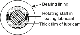
Figure 7.12 Hydrodynamic lubrications

Figure 7.13 Boundary lubrication
Boundary or Thin Film Lubrication
In this kind of lubrication, moving surfaces are separated by a thin layer of lubricant, which is absorbed by physical or chemical forces on the metallic surfaces as shown in Figure 7.13. Here, the continuous film of lubricant cannot persist due to any of the following reasons:
- A shaft starts moving from rest
- The speed is very low
- The load is very high
- The viscosity of the oil is very low
Vegetable oils, animal oils and their soaps possess the property of adsorption either physically or chemically to the metal surfaces and form a thin film of metallic soap, which acts as a good lubricant.
Fatty oils possess greater adhesion property than mineral oil, and to improve the oiliness of mineral oils, a small amount of fatty oils is added. Graphite and molybdenum disulphide are also used for boundary lubrication.
Extreme Pressure Lubrication
In this mechanism, the moving or sliding surfaces are under very high pressure and speed; hence, this is known as extreme pressure lubrication. Under such conditions, a high local temperature is attained, and liquid lubricants fail to stick and may decompose or vaporise.
Special additives are added to mineral oils to meet the extreme pressure conditions and are called extreme pressure additives. Organic compounds having active radicals or groups such as chlorine, sulphur or phosphorous act as good additives. These compounds react with metallic surfaces to form metallic chlorides, sulphides or phosphides as more durable films, capable of withstanding very high loads and temperatures.
7.5.3 Classification of Lubricants
On the basis of their physical state, lubricants can be classified into three categories as listed hereunder.
Liquid Lubricants or Lubricating Oils
Apart from reducing friction and wear, lubricating oil also acts as a cooling medium sealing agent, corrosion preventer, etc. According to origin, lubricating oils are classified into animal and vegetable oils, mineral or petroleum oils and blended oils.
Animal and Vegetable Oils
Vegetable and animal oils possess good oiliness but they are costly, undergo oxidation easily, forming gummy and acidic products, get thickened on coming in contact with air, etc. Hence, they are rarely used as lubricant, but are used as blending agents.
Mineral or Petroleum Oils
Mineral oils are mainly obtained by the distillation of petroleum.
These are widely used lubricants because they are cheap, abundantly available and quiet stable under service conditions. The hydrocarbon oil chain length varies between 12 and 50 carbon atoms. The shorter chain hydrocarbons have lower viscosity than longer chain hydrocarbons.
When compared to animal and vegetable oils, mineral oils possess poor oiliness; therefore, to increase oiliness, high molecular weight compounds such as oleic and steric acids are added.
Blended Oils
In many modern machinery, no single oil serves as the most satisfactory lubricant. Improving important properties by incorporating specific additives is known as blending of oils; such oils give the desired lubricating properties.
Properties of a Good Lubricating Oil
A good lubricating oil must possess the following qualities:
- Low pressure
- High boiling point
- Adequate viscosity to particular service conditions
- Low freezing point
- High oxidation resistance
- Heat stability
- Non-corrosive property and
- Stability to decomposition at the operating temperatures.
Greases or Semi-solid Lubricants
Semi-solids consisting of soap dispersed throughout liquid lubricating oil is grease; the liquid lubricant may be a petroleum oil or even a synthetic oil, and may contain any of the additives for specific requirements.
Preparation
Greases are prepared by the saponification of fat with alkali, followed by adding hot lubricating oil under agitation. The total amount of mineral oil added determines the consistency of the finished grease.
The structure of lubricating greases is like that of a gel. Soaps are gelating agents, which give an interconnected structure by intermolecular forces containing the added oil. The soap dissolves in the oil at high temperature; hence, inorganic solid, thickening agents are added to improve the heat resistance of grease. Greases have higher shear or frictional resistance than oils and can support much heavier loads at lower speeds.
Greases are used in the following situations:
- Where oil cannot remain in place due to high load, low speed, intermittent operation, sudden jerks, etc., for example in-rail axle boxes.
- Bearing and gears that work at high temperatures.
- Where the bearing needs to be sealed against entry of dust, dirt, grit or moisture because greases are less liable to contamination by these.
- Where dripping or spurting of oil is undesirable, because unlike oils, greases do not splash or drip over articles being prepared by the machine. For example, paper manufacturing machines, textiles, edible articles, etc.
The main function of a soap is to acts as a thickening agent; hence, grease sticks firmly to metal surfaces. The nature of the soap decides its consistency, resistance to water and oxidation and temperature up to the grease can be used. Hence greases are classified according to usage soap in their manufacture.
Some of the important greases are as follows:
Calcium-based Greases or Cup-greases
Calcium-based greases are emulsions of petroleum oils with calcium soaps, generally, prepared by adding required amount of calcium hydroxide to hot oil while under agitation. These are the cheapest and the most commonly used greases.
They are insoluble in water and are water-resistant. They are satisfactory for use at low temperatures, because above 80°C, oil and soap begin to separate out.
Soda-base Greases
These are petroleum oils, thickened by mixing sodium soaps. They are not water-resistant, because the sodium soap content is soluble in water. They can be used up to 175°C and are suitable for use in ball bearings, where the lubricant gets heated due to friction.
Lithium-based Greases
They are emulsions of petroleum oils with lithium soaps. They have high water resistance and are suitable only below 15°C.
Axle Greases
They are cheap resin greases and are prepared by adding lime or heavy metal hydroxide to resin and fatty oils. The resulting mixture is thoroughly mixed, allowed to stand and tack or mica-like fillers are finally added. These are water-resistant and are also suitable for less delicate equipment working under heavy loads at low speed.
Besides these, there are greases prepared by dispersing solids (like graphite, soapstone, etc.,) in mineral oil.
Solid Lubricants
Graphite and molybdenum disulphide are the important solid lubricants.
These are used in the following conditions.
- The operating temperature or load is too high.
- The blended lubricating oil or the mixed grease is unacceptable.
- There is a need to avoid combustible lubricants.
The layered structure of graphite and the sandwich-like structure of molybdenum disulphide are shown in Figure 7.14 (a) and (b).

Figure 7.14 (a) Layered structure of graphite (b) Sandwich-like structure of molybdenum disulphide
Hence, the force to shear the crystals parallel to the layers is low and consequently, the parallel layers slide over one another easily. Usually, some organic substances are mixed with solid lubricants so that they may stick firmly to the metal surface.
Solid lubricants are used either in the dry powder form or mixed with water or oil. Graphite is the most widely used lubricant because it is very soapy to touch, non-inflammable and not oxidised in air below 375°C. Graphite is used in the form of powder or suspension in oil or water with the help of emulsifying agent tannin. Graphite is dispersed in oil is called oildag and when dispersed in water, it is called “aquadag”.
In the absence of air, it can be used up to very higher temperature. Graphite is used either in powdered form or as suspension. Graphite greases are used at higher temperature.
7.5.4 Properties of Lubricants
The properties of lubricants are described here.
Neutralisation Number
The acidity or alkalinity of a lubricating oil is determined in terms of its neutralisation number. Determination of acidity is more common and is expressed as the acid value or acid number. It is defined as the “number of milligrams of potassium hydroxide required to neutralise all the free acid present in one gram of the lubricating oil.”
Even the most carefully refined oil may have slight acidity. This is due to the presence of minute amount of organic constituents that are not completely neutralised during the refining treatment or due to traces of residues from the refining process. This small intrinsic acidity may not be harmful in itself, but the degree to which it increases in already used oil is usually taken as a measure of the deterioration of the oil due to oxidation or contamination. In fact, acid number greater than 0.1 is usually taken as an indication of oxidation of the oil.
Saponification Number
The saponification value of an oil is defined as the “number of milligrams of potassium hydroxide required to saponify one gram of the oil”. This is usually determined by refluxing a known quantity of the oil with a known excess of standard KOH solution and determining the alkali consumed by titrating the unreacted alkali.
Animal and vegetable oils undergo saponification but mineral oils do not. Further most of the animal and vegetable oils process their own characteristic saponification values. Hence, the determination of the saponification value helps in ascertaining the presence of animal and vegetable oils in a lubricant. Conversely, since each of the fined oil has its own specific saponification number, any deviation from this value in a given sample indicates the probability and extent of adulteration.
Aniline Point
The aniline point of an oil is defined as “the minimum equilibrium solution temperature for equal volumes of aniline and oil sample”. Aromatic hydrocarbons have high tendency to dissolve natural and synthetic rubbers; this tendency can be determined on the basis of aniline point of an oil. A higher aniline point means lower percentage of hydrocarbons; therefore, having higher aniline point is desirable.
The aniline point is determined by thoroughly mixing equal volumes of aniline and the oil sample in a tube and heating the mixture until a homogeneous solution is obtained. This is allowed to cool at a specified rate until the two phases just separate out. The temperature corresponding to this particular observation is reported as the aniline point.
Cloud Point and Pour Point
Petroleum oils are complex mixtures of chemical compounds and do not show a fixed freezing point. When they are sufficiently cooled, they become plastic solids due to the formation of solid crystals or the congealing of the hydrocarbons present. “The cloud point is the temperature at which this crystallisation of solids in the form of a cloud or haze first becomes noticeable,” when the oil is cooled in a standard apparatus at a standard rate. The pour point is “the temperature at which the oil just ceases to flow when cooled at a standard rate in a standard apparatus”.
The pour point has a greater significance for lubricating oil because it determines the suitability of a hydraulic oil for low temperature installations. Refrigerator plants, air-craft engines, etc., are some important examples, which may be required to start and operate at sub-zero temperatures.
Flash Point and Fire Point
The flash point of an oil is defined as “the minimum temperature at which the oil gives off sufficient vapour to ignite momentarily when a flame of standard dimensions” is brought near the surface of the oil. The fire point of an oil is defined as “the lowest temperature at which the vapours of the oil burn continuously for at least five seconds” when the standard flame is brought near the surface of the oil.
The lubricating oil should have flash point that is reasonably above its working temperature. This ensures safety against fire hazards during usage, storage and transport. The flash point of lubricating oil can be determined by Pensky Marten’s apparatus.
Viscosity and Viscosity Index
Viscosity is one of the most important properties of lubricating oil. The formation of a fluid film of a lubricant between the friction surfaces and the generation of frictional heat under particular conditions of load, bearing spread and lubricant supply mostly depend upon the viscosity of the lubricant and, to some extent, on its oiliness. When large working clearances exist between the friction surfaces, a high viscosity oil is generally recommended to “cushion” the intermediate application of load. However, it is often necessary to sacrifice some of the cushioning effect of viscous oil by the partial substitution of a thinner oil to provide good circulation of oil to dissipate the frictional heat.
If the viscosity of the oil is very low, the fluid lubricant film cannot be maintained between the moving surfaces as excessive wear may take place. On the other hand, if the viscosity of lubricating oil is very high, excessive friction would occur due to shearing of oil. Hence, in hydrodynamic lubrication, the lubricant selected must possess sufficiently high viscosity due to adherence to the bearing and prevent it being squeezed out due to high pressure and yet fluid enough so that the resistance to the shear is not too high. It is, therefore, essential to have knowledge of the viscosity of lubricating oil.
Viscosity is a measure of the internal resistance to the motion of a fluid and is mainly due to the forces of cohesion between the fluid molecules. Absolute viscosity can be defined as the tangential force per unit area required to maintain a unit velocity gradient between two parallel planes in the fluid unit distance apart. The units of absolute viscosity η (eta) in the centimetre-gram-second (CGS) system are poise and centipoise (1/100th of a poise). A poise is equal to one dyne per second per square centimetre. The viscosity of water at 20°C is about a centipoise.
The ratio of absolute viscosity to density for any fluid is known as the absolute kinematic viscosity. It is denoted by η, and in the CGS system, its units are stokes and centistokes (1/100th of a stoke).


The dimensions of dynamic viscosity are HL−1T−1, and the dimensions of kinematic viscosity are L2T−1.
For academic purposes, viscosity is usually expressed in centistoke, but a more common practical measure of the viscosity of an oil is the time in seconds for a given quantity of the oil to flow through a standard orifice under specified set of conditions. Viscosities are usually determined with Redwood viscometer in commonwealth countries, with Engler’s viscometer in Europe and with Saybolt’s viscometer in the USA. In these commercial viscometers, a fixed volume of the liquid is allowed to flow through the standard orifice of particular standard apparatus. Redwood (No. 1) seconds at 25°C. The viscosity of the oil so determined in the time unit is sometimes called relative viscosity. Since the instruments used are of standard dimensions, the kinematic viscosity of the oil in centistokes can be calculated from the time taken by the oil to flow through the standard orifice of the instrument, with the help of the following equations:
μ = Ct (for fluids whose kinematic viscosity is more than centistokes) and
μ = Ct – β/t (for fluids having kinematic viscosities lesser than or equal to 10 centistokes)
μ = Kinematic viscosity in centistokes
t = Time of flow in seconds
C = Viscometer constant
B = Coefficient of kinetic energy, which may be determined experimentally or eliminated by choosing long flow times
For routine purposes, the test viscometer may be calibrated and the constant C determined by using solutions of known viscosity. The primary standard used is freshly distilled water whose kinematic viscosity is 1.0008 centistokes. Other standards usually employed are as follows:
40% sucrose solution:
v = 4.390 cs at 25°C, ρ = 1.17395
60% sucrose solution:
v = 33.66 cs at 25°C, ρ = 1.28335
For Redwood No. 1 viscometer, the values for the constants are as follows:

These constants are based on the results of the work carried out at the National Physical Laboratory at a temperature of 70°F (21.11°C) and with the ranges of viscosity; at that temperature, the results are accurate to ±1%.
Redwood No. 2 viscometer is used for every viscous liquids and gives one-tenth the value of Redwood No. 1 viscometer.
Viscosity Index
The viscosity of an oil decreases with increase in temperature as a result of decrease in intermolecular attraction due to expansion. Hence, it is always necessary to state the temperature at which the viscosity is determined.
In many applications, the lubricating oil will have to function in a machinery over considerably wide range of operating temperatures. If this occurs due to seasonal variations in atmospheric temperature, adjustments can be affected by selecting different oils of appropriate viscosity for different seasons. However, in case of internal combustion engines, aeroplanes, etc., the lubricant used must function at low starting temperature as well as at very high operating temperature. Since the viscosity of lubricating oils decreases with temperature, it is impossible to select an oil having same viscosity over such a wide range of operating temperatures. However, one can select an oil whose variation in viscosity with temperature is minimum. This variation can be indicated either by viscosity temperature curves or by means of the viscosity index. The viscosity index is the numerical expression of the average slope of the viscosity temperature curve of lubricating oil between 100°F to 210°F. The oil under examination is compared with two standard oils having the same viscosity at 210°F as the oil under test. Oils of the Pennsylvanian type crudes thin down the least with an increase in temperature, whereas oils of the Gulf coast origin thin down the most as the temperature is increased.
Hence, the viscosity index of Pennsylvanian oil is taken as 100 and that of the Gulf oil as zero. Then, the viscosity of the oil under investigation is deducted as follows:

where VL = viscosity at 100°F of Gulf oil standard, which has the same viscosity at 210°F as that of oil under test
VX = viscosity of the oil under test
VH = viscosity at 100°F of Pennsylvanian standard oil, which has the same viscosity at 210°F as that of oil under test.
Thus, the higher the viscosity index, the lower the rate at which its viscosity decreases with increase in temperature. Hence, oils of high viscosity index, that is, those having that viscosity temperature curves are demanded for air-cooled internal combustion engines and aircraft engines. In general, oils of high specific gravity have steeped viscosity temperature curves. However, all oils tend to attain the same viscosity above 300°C.
By and large, light oils of low viscosity are used in plain bearings for high-speed equipment such as turbines, spindles and centrifuges, whereas high viscosity oils are used with plain bearings of low-speed equipment.
Mechanical Stability
Four balls extreme-pressure test is one of the important mechanical tests to judge the suitability of a lubricant under conditions of very high pressure, as shown in Figure 7.15. In this test, the lubricant under test is powered in a machine containing four balls. Here, the upper ball is rotated and the lower three balls are stationary. The load is gradually increased, the ball is withdrawn and examined at specific intervals for scale formation, etc., and under a given load, the ball bearings after the test comes out clean if the lubricant desirable. When the load is progressively increased, the liberated heat welds the ball together. Here, the lubricant is said to have completely failed. Hence, this test enables us to determine the maximum load that can be carried safely by a lubricant. The four-balls extreme-pressure lubricant tester is shown in Figure 7.15.

Figure 7.15 Four-balls extreme-pressure lubricant tester
7.5.5 Redwood Viscometer
The Redwood viscometer is made in two sizes. The Redwood No. 1 viscometer is commonly used for determining viscosities of lubricating oils and has an efflux time of 2,000 seconds or less. The Redwood No. 2 viscometer is similar to the Redwood No. 1 type but the jet for the outflow of the oils is of a larger diameter and hence gives an efflux time of approximately one-tenth of that obtained with Redwood No. 1 instrument under otherwise identical experimental conditions. The Redwood No. 2 instrument is therefore used for the oils having higher viscosities such as fuel oils.
The Redwood viscometer does not give a direct measure of viscosity in absolute units but it enables the viscosities of oils to be compared by measuring the time of efflux of 50 ml of oil through the standard orifice of the instrument under standard conditions. The results given by these two viscometers are reported as Redwood No. 1 viscosity or Redwood No. 2 viscosity followed by the efflux time in seconds of the experimental temperature.
Description
The Redwood No. 1 viscometer as shown in Figure 7.16 essentially consists of a standard cylindrical oil cup made up of brass and silvered from inside and has 90 mm height and 46.5 mm in diameter. The cup is open at the upper end. It is fixed with an agate jet in the base. The diameter of the orifice is 1.62 mm and the internal length is 10 mm. The upper surface of the agate is ground to concave depression into which a small silver-plated brass ball is attached to a stout wire can be placed in such a way that the channel is totally closed and no leakage of the oil from the cup through the orifice can take place. The cup is provided with a pointer, which indicates the level up to which the oil should be filled in a cup. The lid of the cup is provided with an arrangement to fix a thermometer to indicate the oil temperature. The oil cup is surrounded by a cylindrical, copper vessel containing water, which serves as a water bath used for maintaining the desired oil temperature with the help of electrical heating oils or by means of a gas burner as the case may be. A thermometer is provided to measure the temperature of water. A stirrer with four blades is provided in a water bath to maintain uniform temperature in the bath, thus enabling uniform heating of the oil. The stirrer contains a broad, curved flange at the top to act as a shield for preventing any water from splashing into the oil cylinder. The entire apparatus rests on a sort of tripod stand provided with levelling screws at the three legs. The water bath is provided with an outlet for removing water as and when needed. A sprit level is used for levelling the apparatus and a 50 ml flask for receiving the oil from the jet outlet is also provided.

Figure 7.16 Redwood viscometer No. 1
Working
The instrument is levelled with the help of the levelling screws on the tripod. The water bath is filled with water to the height corresponding to the tip of the indicator up to which the oil is to be filled in the cylindrical cup. The orifice is sealed by keeping the brass ball in position. Then the oil under test is carefully poured into the oil cup up to the tip of the indicator. The 50 ml flask is placed in position below the jet. The oil and water are kept well-stirred and the respective temperatures are noted. The ball is raised and suspended from the thermometer bracket. Simultaneously, a stopwatch is started. When the level of the oil dropping into the flask just reaches the 50 ml mark, the stopwatch is stopped and the time is noted in seconds. The ball value is replaced in the original position to prevent the overflow of the oil. The experiment is repeated, and the mean value of time of flow for 50 ml of the oil is reported as t seconds, Redwood 1 at T°C. The usual test temperatures stipulated are 21.11°C (70°F), 60°C (140°F) and 93.33°C (200°F).
During the test, the measuring flask should be shielded from draughts with the help of metal shields usually supplied with the instrument.
7.5.6 Engler’s Viscometer
This instrument is diagrammatically presented in Figure 7.17. The water bath is heated by a gas ring, and its temperature is kept uniform with the help of the stirrer. The oil cylinder is fitted with three gauge points, which indicate the amount of oil required and also serve as a means of levelling the instrument. The loosely fitting cover carrying thermometer can be gently rotated to agitate the oil. The jet is slightly tapered and is made of platinum for standard work and nickel for general work. The valve pin, which seats itself in the jet, is lifted at the commencement of a test and is supported in the cover by a cross pin. As the valve pin is lifted, the stopwatch is started and the time of outflow of 200 ml of the oil is determined.
The viscosity is expressed in Engler degrees or degree E by using water as standard. The time of outflow of 200 ml of water at 20°C is taken as 52 seconds. The viscosity in degrees E is calculated by dividing the time m seconds for the outflow of 200 ml of oil by time of outflow of 200 ml of water at 20°C.

Figure 7.17 Engler’s viscometer
7.5.7 Saybolt Viscometer
A single unit Saybolt universal viscometer is shown in Figure 7.18. In a multiple-unit viscometer, a number of oil cups can be accommodated in the same bath, thus enabling tests on a number of oils to proceed at the same time. Instruments can be fitted with an electric immersion heater, a U-tube for steam heating or water cooling and a gas ring, which is placed inside the air jacket surrounding the water bath. The bath liquid is stirred by rotating the cover by means of the two handles as a turn-table arrangement.
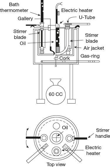
Figure 7.18 Saybolt viscometer
The temperature can be regulated by running cold or warm water through the U-tube irrespective of the heating arrangement used. The jet is made of a hard non-corrodible metal such as monel or stainless steel. The lower end of the jet opens into a larger tube. This tube, when stoppered by a cork, becomes a closed air chamber preventing the oil flowing out (Figure 7.18).
To start the test, the bath is brought to the test temperature and the oil is heated to the same temperature in a separate vessel. The oil is then poured into the oil cylinder and stirred with the oil thermometer and any excess oil flowing over into the surrounding gallery. When the oil and the bath are at the same temperature, the oil thermometer is removed, the excess oil drawn off from the gallery with a pipette, the cork withdrawn and the stopwatch started. The collecting flask is arranged such that the oil stream will strike its neck, thus avoiding the formation of foam.
For very viscous fuels, a viscometer with a larger jet known as the Saybolt furol viscometer is used. The Saybolt universal viscometer can be used for oils having flow times of more than 32 seconds. There is no maximum unit; but in general, for liquids having flow times over 1,000 seconds, the Saybolt furol viscometer is better.
7.5.8 U-Tube Viscometer
The standard U-tube viscometer (Figure 7.19(a) and (b)) is an improved form of the Ostwald viscometers, which is used for the determination of the absolute viscosity of lubricating oils. The determination of absolute viscosity of lubricating oils by the U-tube viscometer based on Poiseuille’s law.

where V = volume of the liquid flowing through a capillary tube of length l (cm) of uniform radius r (cm) in a times t (seconds) and η (poise) is the coefficient of viscosity of the liquid at the particular temperature.
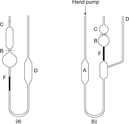
Figure 7.19 U-tube viscometers (a) standard U-tube viscometer (b) Ubbelohde suspende level viscometer
The determination of absolute viscosity by the U-tube viscometer essentially consists of measurement of the time of passage through the capillary of a fixed volume of liquid under a fixed mean hydrostatic head ρ of the liquid. If the density of the liquid is d, then P ∝ d and since, for a given viscometer, η ∝ td.
![]()
where k is the proportionality constant; It can be determined for different viscometers from its known dimensions or by calibration with a standard liquid such as water or any other liquids.

7.5.9 Conversion of Redwood, Engler and Saybolt Viscosities into Absolute Units
Redwood, Engler and Saybolt instruments are not the ideal methods of determining absolute viscosities. The conversion values are only considered good approximations when only taken at the same temperature.
Therefore, the conversion of the aforementioned relative viscosities to absolute viscosities is done with the help of the following equation:

![]()
c and β are constants.
Values of c and β are given in Table 7.2.
Table 7.2 Values of c and β

7.6 EXPLOSIVES AND PROPELLANTS
Explosives
An explosive is a “substance or compound or mixture, which when subjected to thermal and mechanical shock, gets very rapidly oxidised exothermically with a sudden release of potential energy”.
The explosive reaction is exothermic, so the products get heated to a high temperature and a high pressure is exerted on the surroundings. The amount of power available from a given weight or volume of explosive, is called “power to weight ratio”.
7.6.1 Some Important Terms about Explosives
Some important terms about explosives are as follows:
Explosive Strength
It is the energy liberated per unit mass of the explosive (cal/g).
Velocity of Detonation
It is the velocity with which the given explosive detonates.
Sensitivity
It can be determine the effect and impact of friction, heat, electric spark or detonator wave etc., on explosives. Some explosives may detonate by a feather touch, whereas some may not detonate even with a hammer blow. Sensitivity plays a key role in the selection of explosives for a particular purpose.
Brisance
It indicates the shattering power of an explosive.
7.6.2 Classification of Explosives
Explosives are broadly classified into three groups.
Detonators/Primary Explosives/Initiating Explosives
These are highly sensitive, and explode on receiving a slight-shock or when exposed to fire. Hence, they should be handled with utmost care. Some of examples are as follows:
Lead Azide (PbN6)
It is very popular for military uses due to low cost, excellent initiating action and stability in storage.
Mercury Fulminate [Hg(CNO2)]
It is more sensitive and expensive than lead azide. It is slightly toxic.
Tetracene (C2H7N7O)
It requires low initiating action; ignites easily with high heat of explosion and produces a large volume of gases.
Diazodinitro Phenol (DDNP)
It is quite sensitive and has high brisance and consequently can initiate explosion even in less sensitive high explosives.
Propellents or Low Explosives
These are simply burns and do not explode all of a sudden. The chemical reactions taking place in such explosives are slow and their burning proceeds from the surface inwards in layers at an approximate rate. The gases evolved disperse readily without building high pressure and consequently, they can be easily controlled. Some of examples are as follows:
Gun Powder or Black Powder
It is a mixture of 75% potassium nitrate, 15% charcoal and 10% sulphur. The explosive reaction is
![]()
If excess of carbon and sulphur take part in slower processes, it leads to evolution of more gases.
It is an excellent and a cheap explosive for blasting down of coal, as its low velocity gives it a slow heating action that does not shatter the coal unduly. Hence these are known as time in delay-fuses; used for blasting in shells, igniters and primer assemblies for propellants, practice bombs and saluting charges.
Nitrocellulose
It is prepared by treating cellulose with nitric and sulphuric acids. Formed nitrocellulose is dissolved in a mixture of ether and alcohol and the solvent is evaporated, leaving a jelly-like solid behind. It is study by adding stabiliser like diphenylamine and pressed into cylindrical rods. It is called smokeless powder as it produces smokeless gases such as CO2, CO, N2 and water vapour.
High Explosives
Explosives which have high energy content than the primary explosives are called high explosives. These are quite stable and are insensitive to fire, mechanical shocks, etc. Hence, to start a rapid chemical reaction, some amount of primary explosives are placed with high explosives.
These are broadly divided into four groups:
Single Compounds Explosives
These contain only one chemical compound. Some of examples are as follows:
- Ammonium nitrate: It is very stable, nontoxic and cheap and has low brisance value. It is about half as powerful as TNT and is mostly employed in making binary explosives. It is dangerous to store near any inflammable material.
- TNT (Trinitrotoluene): It is high explosive. It is most widely used in shell-firing and under-water explosions and is well-suited for loading in containers, due to low melting point. It is a safe explosive in manufacture, transportation, storage, non-hydroscopic and violent disruptive explosive, and does not react with metals. Hence, it is used for military purposes.
- PETN (Pentaerythritol tetra nitrate): It is an extremely powerful, sensitive and standard military explosive.
- RDX or cyclonite: It is a powerful, sensitive, less toxic, high explosive. RDX came into prominence in military as well as an industrial explosive.
Binary Explosives
Binary explosives are a mixture of TNT and other explosives, and these are more convenient and superior than single explosives. Due to their low melting point, TNT is one of the ingredients in all binary explosives.
For example,
- TNT + Ammonium nitrate is amatol.
- TNT + PETN is pentolite.
- TNT + Tetryl is tetrytol.
- TNT + RDX + Al powder is tropex.
- TNT + Al flakes is titronal.
Plastic Explosive
These are a combination different explosives which are in plastic state. They can be hand moulded and made into various shapes without any serious risk and are mainly used for industrial applications and military uses. With high explosive simple combination of plastic explosive can prepare. Due to their engineering applications, they are available as flexible sheets.
Dynamites
These are explosives containing nitroglycerin as the main ingredient, by pressure or shock detonates.

The explosion is so sudden that it would shatter the breech of the rifle, before the bullet had time to move. It also pulverises the rock, instead of breaking it into fragments of immovable size. It is dangerous in handling and transporting and is usually mixed with an insert absorbent like wood pulp, starch, meals, etc. Some examples are as follows:
- Straight dynamites: They contain 15–60% nitroglycerine in wood meal with sodium nitrate. The important uses are blasting of hard rocks, coal and other minerals.
- Blasting gelatin-dynamites: It is the combination of nitroglycerene (91.5%) partly gelatinised by nitro cotton (8%) or colladion cotton and CaCO3 (0.5%). These are very powerful, water-proof and stick well in holes into which they have been loaded. They can be used under wet conditions, where high loading density is desired.
The important uses are submarine blasting, tunnel driving, deep-well shooting and at places where maximum shattering effects are desired.
- Gun cotton (or cellulose nitrate): Cotton is steeped for half an hour in a cooled mixture of concentrated nitric acid and concentrated sulphuric acid.

- Cordite: It is a form of smokeless powder made by dissolving guncotton (65 parts), nitroglycerine (30 parts) and petroleum jelly or vaseline (five parts) in acetone. The resulting paste is rolled and cut into pieces of different dimensions, according to the rate of explosion desired. When acetone evaporates, the horny cordite remains. The vaseline acts as a stabiliser and a cooling agent on the powder as it has a tendency to lower the temperature of explosion. The guncotton slows down the explosive reaction of nitroglycerine and makes cordite an excellent propellant for large calibre naval guns.
- Gelignite: It consists of 65% blasting gelatine and 35% of absorbing powder. It is a powerful explosive, which can be used under water.
7.6.3 Precautions during Storage of Explosives
The following precautions should be taken while storing explosives:
- Explosives should be stored separately, that is, without mixing with others.
- Detonators and explosives should be stored separately.
- Flame lanterns should not be used. In case of power failure, only torches should be used for lighting purposes.
- All electric fittings and wirings should be properly insulated and frequently checked.
- Only authorised persons should be allowed to the explosive store by wearing magazine shoes.
- One should take care of jerks or drops while handling explosives.
- Smoking/fire should be strictly prohibited around the explosive store.
- The magazine (explosive store) should not be constructed within 500m from any working kiln or furnace.
- The boundary of the explosive store should be protected by high barbed wire fencing and proper caution boards should be put up.
- The magazine should be provided with heightening conductors as a safeguard.
- During thunder, the magazine should not be opened and no one should be allowed inside.
7.6.4 Blasting Fuses
A fuse is “a thin water-proof canvas length of tube containing gunpowder (or TNT) arranged to burn at a given speed for setting off charges of explosives. Fuses are of two types as follows.
Safety Fuse
It is employed in initiating caps, where electrical firing is not used. A safety fuse consists of a small diameter core of black powder, enclosed in a covering of wrapper of water proofed fabrics. It is made to have an approximate burning speed of 30–40 seconds per foot (or about 1 cm s-1). When a fuse is used to fire a shot in blasting, sufficient length is used so that ample time is allowed for the shot firer to reach a point of safety.
Detonating Fuse
It has a velocity of over 6,000 m/s and consists of a charge of high velocity explosive, such as TNT, contained in a small diameter bent tube. The line of fuse (called Cordean) is in contact with the charge throughout its length and this causes practically instantaneous detonation of the whole charge, regardless of its velocity. Such fuses are used principally for exploding charges of explosive in deep holes.
7.6.5 Important Explosives and their Preparation
- Lead AzidePb(N3)2 is prepared by reacting sodamide (formed by reacting ammonia with sodium) with nitrous oxide (N2O), followed by treating the sodium azide (NaN3) so-formed with lead acetate.
Thus;
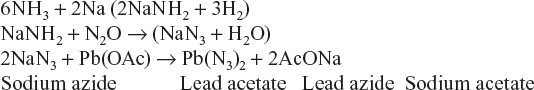
- Mercury Fulminate Hg(ONC)2is prepared by dissolving mercury in excess of HNO3 and then pouring the resulting solution of ethyl alcohol, when the solution starts boiling and mercury fulminate is precipitated.
Decomposition reaction: Hg(ONC)2 Hg(g) + N2 + CO + 117 k Cal
- Diazodinitrophenol (DDNP) is prepared by diazotising picranic acid.

- Trinitrotoluene (TNT) is prepared by the nitration of toluene (C6H5CH3) using a nitrating mixture of concentrated HNO3 and concentrated H2SO4 in 1:1 ratio in a tank reactor, in which contents are continuously stirred.

The liquid product (TNT) so formed is taken out, washed with ammoniacal solution of Na2SO3 and then with cold water, when TNT crystallises out. Crystals of TNT are filtered and purified by melting. The melt is dried (by passing warm air) and poured in containers.
Decomposition reaction: TNT (3.5CO + 3.5C + 2.5H2O + 1.5N2 + 190 K cal
- Nitroglycerine (NG) or glycerol trinitrate (GTN) is prepared by adding glycerol to a cooled mixture of concentrated H2SO4 (60%) and concentrated HNO3 (40%) at 10°C with constant stirring.

After nitration, the mixture is run into a tank, when the nitroglycerine rises to the top, while excess acids form the lower layer. The nitroglycerine layer is separated, washed first with water and then with dilute sodium carbonate solution (2%) to remove traces of acids completely. It is then converted into different desired types of dynamites by absorbing in specific inert materials.
Decomposition reaction: 4C3H5(NO3)2(12CO2 + 6N2 + 10H2O + O2
- Pentaertythrital Tetranitrate (PETN) is prepared by the cannizaro reaction between formaldehyde and acetaldehyde in the molar ratio 4:1.

Decomposition reaction: C(CH2ONO2)4(3CO2 + 2CO + 4H2O + 2N2 + 180 K Cal
- RDX or Cyclonite (Cyclomethylene trinitro amine) is prepared by treating hexamethylene tetra amine with nitric acid.

7.6.6 Rocket Propellants
A rocket propellant is a high oxygen-containing fuel plus oxidant whose combustion takes place in a definite and controlled manner with the evolution of a huge volume of gas. A propellant reacts quickly, producing a very large volume of hot gases (usually at a temperature of 3,000 °C and a pressure of 300 kg/cm2), which exits through a small opening (called “jet” or nozzle) at supersonic velocity. This act of pushing the gas backwards produces an equal and opposite reaction—Newton’s third law of motion, which moves the rocket forward. With the increase of exhaust velocity, the rocket performance increases. Rockets are used for pyrotechnic effect signalling, carrying a life, hurling explosives at an enemy, putting space capsule into orbit, etc. (Figure 7.20).
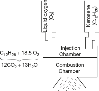
Figure 7.20 Use of bipropellant in a rocket. Combustion reaction between kerosene and liquid oxygen produces a huge volume of gaseous CO2 and H2O, the thrust of which forces the rocket upwards with a high speed
7.6.7 Characteristics of a Good Propellant
The characteristics of a good propellant are as follows:
- It should have high specific impulse (specific impulse is the thrust delivered divided by the rate of propellant (fuel plus oxidant) burnt.
- It should produce low molecular weight products (like H2, CO, CO2 and N2) during combustion.
- It should burn at a slow and steady rate.
- It should possess low ignition delay (ignition delay is the time taken by propellant to catch fire in the presence of an oxidising agent. It is expressed in milliseconds)
- It should possess high density.
- It should be stable over wider ranges of temperature.
- It should be safe to handle and store under ordinary condition, that is, it should not detonate under shock, heat or impact.
- It should be non-corrosive and non-hydroscopic.
- It should be readily ignitable at a predictable burning rate.
- It should leave no solid residue after ignition.
- It should not produce toxic products.
- It should produce high temperature on combustion.
Note: Specific impulse is the thrust in kg per second on the fuel burnt. The value of thrust (or propulsive force) due to momentum of the exiting gases and is given by the following formula:
![]()
where F = thrust (kg/m/kg)
m = mass flow (kg)
g = acceleration due to gravity (9.81 m2/s)
v = exhaust velocity (m/s)
Pe = exit pressure (kg/m2)
Pa = ambient gas pressure (kg/m2)
and Ae = nozzle exit area (m2)
7.6.8 Classifications of Propellants
The chemical propellants are classified into solid and liquid categories.
Solid Propellants
These may be “homogeneous” or “composite”. When a solid propellant or a mixture of propellants are thoroughly mixed in a colloidal state, it is called homogenous solid propellant.
When a single propellant is employed, it is called a single-base propellant. For example, nitro cellulose, also known as guncotton or smokeless powder. On the other hand, a solid propellant which contains two materials is called a double-base propellant. For example, ballistite, containing nitro cellulose and nitroglycerine mixture, is a powerful double-base solid propellant. Cordite, composed of 65% nitrocellulose, 30% of nitro cellulose and 40–45% nitroglycerine. Diethyl phthalate, up to 5%, is also added and this acts as a solvent cum plasticiser, thereby giving a homogenous plastic mass, which can be worked smoothly. In addition, up to 1% of diphenylamine is added, which acts as a stabiliser. The propellant gives a flame temperature of about 2,700°C and the volume of gases is about 1,500 times the original volume.
When an oxidising agent is dispersed in a fuel mass, the solid propellant is heterogeneous or composite. Gunpowder is the oldest composite propellant. It gives a flame temperature of 800–1,500°C and volume of gases is about 400 times the volume of the charge. Other composite solid propellants are 75% potassium per chlorate plus 25% asphalt oil, 80% ammonium perchlorate plus 20% resin (rubber) binder, 46% ammonium picrate, 48% sodium nitrate and 8% plastic resin binder. In selecting the oxidiser, it should be seen that it is non-hygroscopic, stable in contact with fuel and does not form any corrosive products. The oxidant potassium perchlorate leaves behind a white residue of potassium chloride particles; while ammonium perchlorate leaves no solid residue, but its combustion products contain hydrogen chloride and water, which form a toxic and corrosive fog.
Liquid Propellants
They possess many advantages over solid propellants. Thus, liquid propellants are more versatile and the engine using them can be checked and more easily calibrated. However, unlike solid propellants, the engine using liquid propellant is quite delicate and cannot withstand any rough handling. Liquid propellants may be monopropellants or bipropellants.
Monopropellants
It has fuel as well as oxidiser in the same molecule or in a solution containing both these. For example, hydrogen peroxide, nitromethane, ethylene oxide hydrazine propyl nitrate and a mixture of 21.4% methanol and 78.6% hydrogen peroxide are some of the common propellants (mono). A monopropellant must be safe to state and at the same time, it should burn smoothly. Due to its reactivity, hydrogen peroxide is not easy to store and handle. Moreover, metal oxides catalyse decomposition. Therefore, storage tanks are made of special materials for the same.
Bipropellants
These are more widely used. Here, liquid fuel and oxidiser, kept separately, are separately injected in the combustion chamber. The commonly used fuels are liquid hydrogen, hydrazine, ethyl alcohol, aniline and kerosene oil. Ethyl alcohol admixed with 25% water is a good fuel. Although the addition of water reduces flame temperature, it reduces the molecular mass of combustion gases, which compensates for reduction in performance. The common oxidisers employed are liquid oxygen, ozone, hydrogen peroxide, fuming nitric acid and liquid flourine. Liquid oxygen is a non-toxic, safe and good oxidising agent, but it has to be stored under pressure in insulated containers. Ozone is a very powerful oxidising agent, but it is quite toxic and can explode at high concentration. Liquid flourine is volatile, toxic, corrosive, very reactive, but is a very good oxidising agent. It is also difficult to store and handle it.
7.7 NANOMATERIALS
Nanoscience and technology are considered one of the most promising fields having huge potential to bring countless opportunities in many areas of research and development. It is the study of tiny structures at nanometer scale, which forms a basis for several core technologies.
Definition
“Nanotechnology plays a key role in many areas”.
“One nanometer is one billionth of a meter”.
1 nm = 1/1,00,00,00,000 of a metre, which is close to 1/1,00,00,00,000 of a yard.
For getting easy sense of the nanoscale, it is suffice to know that a human hair has around 50,000 nm and a commonly used microchip has around 150 nm. The normal human eye can see the things which have the size above 10,000 nm only.
Note on Measures
Almost all nanosciences are discussed by using SI measurements; SI Units and their description shown in Table 7.3.
Table 7.3 Measuring units and their description

7.7.1 Synthesis of Nanomaterials
Nanotechnology has sprung into prominence due to the recent development of various synthesis techniques/methodologies and the discovery of modern tools for the characterisation and manipulation of nanomaterials. Synthesis techniques are broadly categorised as top-up approach and bottom-up approach. Some of the methods for synthesis of nanomaterials are as follows:
- Vapour–liquid–solid growth
- Solution–liquid–solid growth
- Template–mediated growth
- Electron beam lithography
- Reverse micellar route, etc.
Preparation of Copper and Nickel Nanooxalates by Reverse Micelle Route
The reverse micellar route is the best method for synthesis of variety of nanoparticles due to the ability to mix the reactants efficiently and control the size of nanoparticles effectively.
The synthesis of these nanorods have been achieved using two micro-emulsions as described here:
- Microemulsion I is the mixture of cetyl trimethyl ammonium bromide (CTAB) as a surfactant and n-butanol as the co-surfactant. Here, isooctane or n-octane is used as a hydrocarbon phase and 0.1 M copper nitrate/nickel nitrate solution is used as the aqueous phase.
- Microemulsion II comprises the same constituents as microemulsion I, except for having 0.1 m ammonium oxalate instead of copper nitrate or nickel nitrate as the aqueous phase. The weight fractions of various constituents in these microemulsions are 16.76% of CTAB, 13.90% of n-butanol, 59.29% of isooctane and 10.05% of the aqueous phase. These two microemulsions were mixed slowly and stirred overnight on a magnetic stirrer, and the resulting precipitate was separated from the apolar solvents and surfactants by centrifuging and washing it with 1:1 mixture of methanol and chloroform. The precipitate is then dried in air.
7.7.2 Characterisation
The nano materials are characterised by X-ray diffraction, transmission electron microscopy, scanning electron microscopy, (TEM, SEM and AFM), dynamic light scattering studies (DLS), thermal analysis (TGA/DTA), Fourier transform infrared spectroscopy (FTIR), X-ray photoelectron spectroscopy (XPS), field dependent magnetisation studies, etc.
7.7.3 Importance
- The synthesis of nanowires and nano rods has generated a lot of interest in the recent years due to their importance as objects for understanding microscopic systems.
- Nano-structured wires and rods are expected to have interesting optical, electrical, magnetic and mechanical properties as compared to micron-sized whiskers and fibres.
- There also find potential use as nanowires in the area of biosensors, where a specific molecule is attached to the tip of the nanowire, which then identifies a particular molecule in the living system.
7.7.4 Broad Classification of Nanomaterials
According to the arrangements of atoms or molecules, nanomaterials are broadly classified into three types as follows:
- Materials which have one dimension in the nanoscale.
For example, surface coatings and thin films.
- Materials which have two dimensions in nanoscale.
For example, nanowires and nanotubes.
- Materials which have three dimensions in nanoscale or quantum dots.
For example, fullerenes, cadmium-selenium quantum dots, gold quantum dots, ZnO quantum dots, etc.
Some Other Nanomaterials
Super-paramagnetic iron oxide nanoparticle, ZnO nanoparticle, titanium oxide nanoparticle, carboncoated silver nanoparticles, gold nanoparticle, NaYF4 nanophosphors, CdS nanowires, ZnS nanorods, Fe3O4 nanoparticles, etc., are some other nanomaterials.
7.7.5 Fullerenes
A fullerene is a molecule of carbon in the form a hallow sphere, ellipsoid, tube and many other shapes. A spherical fullerene are also called Buckminsterfullerene (bucky balls); they resemble the balls used in football. The cylindrical one is called carbon nanotubes or bucky tubes. The fullerene is similar to structure graphite, which is composed of stacked graph sheets of linked hexagonal or pentagonal rings.
Buckminsterfullerene (C60) was prepared in 1985 by Richard Smalley, Robert curl, James heath, Sean O’Brien and Harold Kroto. Kroto, Curl and Smalley were awarded the 1996 Nobel Prize in Chemistry for their roles in the discovery of this class of molecules.
7.7.6. Types of Fullerenes
The types of fullerenes are discussed in this section.
Bucky Ball Cluster
Since the discovery of fullerenes in 1985, many types of fullerenes like Bucky ball clusters, nanotubes, mega tubes, nano “onions”, linked “ball and chain” dimmers and fullerene rings are prepared.
The most common bucky ball is C60 as shown in Figure 7.21.

Figure 7.21 Common buck ball
Buckminsterfullerene was named after Richard Buckminster Fuller, a noted architectural modeller who popularised the geodesic dome. As buckminsterfullerenes have a shape similar to that sort of a dome, the name seemed to be appropriate. As the discovery of the fullerene family came after buckminsterfullerene, the shortened name “fullerene” is used to refer to the family of fullerenes. The suffix “-ene” indicates that each C atom is covalently bonded to three others (instead of the maximum of four), a situation that classically would correspond to the existence of bonds involving two pairs of electrons. Buckminsterfullerene is the smallest fullerene molecule containing hexagonal and pentagonal rings, in which two pentagons share on edge. It is also the most common is terms of natural occurrence, as it can often be found in soot.
The structure of C60 is a tralancated icosahedron, which resembles an association football of the type made of 20 hexagons and 12 pentagons with carbon atom at the verities of each polygon and a bond along each polygon edge. The Van der Waals diameter of a C60 molecule is about 1.1 nm. The nucleolus to nucleolus diameter of α C60 molecule is about 0.71 nm. The C60 molecule has two bond lengths.
Applications
Fullerenes have been extensively used for several bio-medical applications including the design of high performance MRI contract agents, X-ray imaging contract agents, photo dynamic therapy and drug and gene delivery and have been summarised in several comprehensive reviews.
Carbon Nanotubes
Nano tubes are cylindrical fullerenes. These tubes of carbons are usually only a few nanometers wide, but they can range from less than micrometer to several millimeters in length. They often have closed ends but can be open-ended as well. Their unique molecular structure results in extraordinary microscopic properties including high tensile strength, high electric conductivity, high ductile, high heat conductivity and relative chemical in actively.
Hallow tubes of very small dimension with single or multiple walls having potential application in electronics and industry. Carbon nanotubes have been identified into three structures namely, armchair, zigzag and chiral structure (Figure 7.22 (a), (b) and (c)).
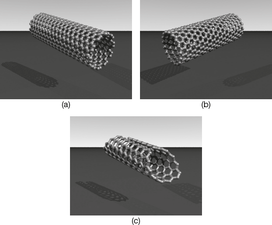
Figure 7.22 (a) Armchair (n, n), (b) Zigzag (n, 0), (c) Chiral (n, m)
Due to well-defined geometry, exceptional mechanical properties and extraordinary electrical characteristics of carbon nanotubes (CNTs) are used as nanoelectric circuits, nanoelectrochemical systems, nonorobots, etc.
Synthesis of Carbon Nanotubes
Carbon nanotubes, including powder and array types, are generally produced by three main techniques.
- Electric arc discharge method
- Laser ablation method
- Thermal or plasma-enhanced chemical vapour deposition method
Laser ablation and arc discharge methods are modified physical vapour deposition techniques and involve the condensation of hot, gaseous carbon atoms generated from the evaporation of solid carbon.
In arc discharge, vapour is created by an arc discharge between two carbon electrodes with or without a catalyst. The nanotube self-assemble from the resulting carbon vapour laser ablation produces a small amount of clean nanotubes, whereas arc discharge methods generally produce large quantities of impure material. Laser ablation and arc discharge techniques produce powder-type nanotubes with impurities in the form of amorphous carbon and catalyst particles because of the high temperature of the heat source. The chemical vapour deposition method is a better technique for high yield and low impurity production of carbon nanotube arrays at moderate temperatures. Plasma-enhanced chemical vapour deposition can grow individual, free-standing nanofibers with special controlling ability. On the other hand, high-density aligned nanotubes can be mass-produced using thermal chemical vapour deposition. The method also provides good control over the size, shape and alignment of the nanotubes.
Recently, Kang et al. have synthesised dense, perfectly aligned arrays of single-walled nanotubes, and Vijayaraghavan et al. have been able to horizontally align individual nanotubes on a large scale using dielectrophoretic force. Nanotube materials for analytical applications should be clean with low impurities from metal catalysts and amorphous carbon. The synthesis of nanotubes with a uniform size and special density is critical before post-processing and functionalisation.
Applications of Carbon Nanotubes
- Carbon nanotubes are used in the preparation of nanoelectric circuits, nanoelectromechanical systems and nanorobotic systems.
- Multi-walled carbon nanotubes can serve as bearings, switches, gigahertz oscillators, memories, shuttles, syringes, etc.
- The hollow carbon nanotubes can be used as containers, conduits, pipettes, coaxial cables, etc.
Carbon Nanotubes as Nano Biosensors
Carbon nanotubes have become the forces of intensive research by analytical chemists, as electrodes to transmit electrical signals or as sensors to detect concentrations of chemicals, biological materials. Fascinating physical and chemical properties such as electrical conductance, high mechanical stiffness, light weight, electron-spin resonance, field emission, electrochemical actuation, transistor behaviour, piezoresistance, contact resistance, coulomb drag power generation, thermal conductivity, luminescence, electrochemical bond expansion, opto-mechanical actuation and the possibilities of functionalising carbon nanotubes to change their intrinsic properties are the reasons for their use as novel biosensors.
The structure of nanotubes can be described as a rolled-up tabular shell of graphite sheet with the carbon atoms covalently bound to their neighbours. The helicity of the shell categorises nanotubes into metallic or semiconducting types. Based on the capture and promotion of electron transfer reaction from analytics, ballistic conductivity of metallic nanotubes is extremely attractive. Semiconducting nanotubes can be used as biosensors directly because these are optimised by changing the gate voltage. Hence, CNT electrodes have high sensitivity with low detection limit. CNT can be described as single wall nanotubes (SWNT), double wall nanotubes (DWNT) or multi-wall nanotubes (MWNT). CNT diameters range from about 1.4 nm to 60 nm and their length varies from microns to above one centimeter.
To use nanotube electrodes for electro analytic purposes, proper conjugation strategies between biological molecules such as enzymes, single stand DNA/RNA/PNA, antibodies, receptors and aptamers need to be developed. Appropriate functionalisation methods and immobilisation of biomaterials on nanotubes are critical since functional groups create defects in the nanotubes that will eventually alter or degrade the intrinsic electrical properties of the nanotube. Nanotubes also have contact resistance that should be minimised to provide the highest sensitivity when used as a sensor.
Carbon Nanotubes as Nanorobotics
Robots can do all kinds of physical and mechanical work more in various situations instead of manpower. Nowadays, large-sized robots are used, and shrinking the robot size to nanoscale with carbon nanotube is a fascinating advantage. Nanorobots can measure mass in femtogram ranges, sensing forces at piconewton scales, etc., and with a provision for advanced features nanorobots can introduced in army, intelligence, security, mechanochemical synthesis, etc.
7.7.7 Properties of Nanomaterials
The advent of nanotechnology has resulted in the increased use of nanomaterial-based products in daily life. A significant increase in the surface-area-to-volume ratio at the nanoscale, giving rise to novel and enhanced magnetic, mechanical, electronic, catalytic, conducting and optical properties of nanomaterials, has made nanotechnology the most promising tool of this century.
Size
Nanostructures are the smallest of human-made things but the largest molecules of natural things and nanometer is the magical point on the scale. Nanoscience and technology provide advanced materials and systems which are intermediate between isolated atoms and bulk materials, with controlling of transitional properties. Due to drastically increased surface-to-volume ratio, physical and chemical properties are quite different from the bulk but tend to dominate at nanoscale.
Optical Properties
Due to large surface area, nanomaterials exhibit better optical properties. Luminescent nanocrystals, termed as nanophosphors, with unique optical properties make them ideal for a wide spectrum of applications ranging from flexible displays, lasers to biological imaging and therapeutic agents. For example, NaYF4 is a highly multifunctional material with promising potential application in IR to visible up conversion process. Silicon nanowires show strong photoluminescence.
Mechanical Properties
The mechanical behaviour of nanomaterial are found to be high strength, good ductility, superior superplasticity, a low-friction coefficient, good thermal stability, high wear resistance, enhanced high-cycle fatigue life and good corrosion resistance.
For example, tensile strength of carbon nanotube is approximately 20 times greater than the steel.
Magnetic Property
The magnetic property of a nanomaterial is very useful in biological systems. Due to unique properties and biocompatibility of nanoparticles, they easily combine with biological materials like proteins, antibodies, enzymes, nucleus acids, etc.
Electrical Properties
Nanomaterials show electrical conductivity from semiconductors to superconductors, depending upon the diameter and chirality of the molecules. Nano-structured conducting polymers have generated much interest for their potential use in nanoelectronics.
For example, fullerenes are a class of allotropes of carbon, which are basically graphene sheets rolled into tubes or spheres. They include the carbon nanotubes because of their mechanical strength and electrical properties.
Carbon nanotubes have higher electrical conductivity than copper wires. The high electrical conductivity of nanotubes is mainly negligible amount of defects, so they possess low resistance.
Semiconductors
Most nanomaterials show semi-conductivity.
For example, carbon nanotubes, nanowires, MoS2, etc. They are used mainly as field-effect transistors, p-n diodes, etc.
Superconductors
Some nanomaterials at low temperature show superconductivity.
For example, at normal temperature, NbS2 is metallic in nature, but at low temperature, it becomes a superconductor.
Catalytic Activity
Due to the increasing surface area, nanomaterials act as a good catalyst in different homogeneous and heterogeneous phases.
- For example, In2O3-Ga2O3/Al2O3 nanocomposite used in selective catalytic reduction of nitric oxide.
- Platinum, a precious transition metal, which has outstanding catalytic and electrical properties and superior resistant characteristics to corrosion, has been widely applied in chemical, petrochemical, pharmaceutical, electronic and automotive industries. Both platinum metal and its alloys possess distinctive ability in catalysing partial oxidation, hydrogenation and dehydrogenation of a variety of important molecules that are essential in many industrial processes.
7.7.8 Applications of Nanomaterials
Due to the advent of nanotechnology, applications of nanomaterials are quickly increasing by the day.
- Conducting polymers are widely employed as coatings conferring electrode systems, antifouling properties and possibly activating electrocatalytic redox processes, conducting polymers for commercial applications due to their high conductivity, easy preparation and environmental stability have generated much interest for their potential use in nanoelectronic and organic conductors.
- Aurum nanoparticles have been used for the enhancement of radiation effects on bovine aortic endothelial cells of superficial X-ray radiation therapy and megavoltage electron radiation therapy beans.
- Nanoparticles are used as important catalysts in different chemical reactions.
- Quantum dots and quantum wires have been used in the design of new super computers.
- Magnetic nanoparticles have wide application in medicine as drug transport and biosensor.
- Carbon nanotubes having fascinating physical and chemical properties such as electrical conductance, high mechanical stiffness, light weight, electron spin resonance field emission, electrochemical actuation, transistor behaviour, piezoresistance, contact resistance, coulomb drag power generation, thermal conductivity, luminescence, electrochemical bond expression, opto-mechanical actuation, and the possibilities of function-aligned CNTs to change their intrinsic properties are the reasons for their use in different ways as follows:
- They are used as a novel biosensor as enzyme electrodes, immunosensors, DNA, RNA, electrodes, etc.
- Due to well-defined geometry, exceptional mechanical properties and extraordinary electric characteristics, among other outstanding physical properties of CNTs, they are qualified for potential applications in the preparation of nanoelectronic circuits, nanoelectromechanics systems, nanorobotics systems, structural elements, probes, grippers, tweezers, scissors, actuators, bearings, syringes, switches, memories, diodes, transistors, logic gates, wires, cables, position sensors, displacement sensors, circuits, thermal actuators, etc.
- They are used in field emission light devices for fluorescent displays.
- They act as a storage device in lithium batteries.
- From household uses to industries, space, army, medicine, agriculture and other fields, nanotechnology applications are employed.
7.8 LIQUID CRYSTALS
The study of liquid crystals began in 1888 with the observation of two distinct melting points to cholesteryl benzoate by Friedrich Reinitzer.
Liquid crystals constitute a fascinating state of aggregation that is intermediate between the crystalline solid and the amorphous liquid. They exhibit rheological behaviour similar to those of liquids and anisotropic physical properties similar to crystalline solids. Their dual nature and easy response to electric, magnetic and surface forces have generated innumerable applications, which are extended over diverse fields. The explosive growth of application of liquid crystals has generated immense interest amongst the scientists and technologists to synthesise, characterise and understand the substances.
“Liquid crystal is formed in between the temperature of transition point and melting point, the cloudy liquid shows double refraction. Hence the cloudy liquid is known as liquid crystal or mesomorphic state”.
“The liquid crystals are highly anisotropic fluids that exist between the boundaries of the solid and conventional, isotropic liquid phase”.
Liquid crystals are made up of liquid and crystals. The term “liquid” is used because the tendency to take the shape of the container and the word crystals is used because they still contain one or two dimensional arrays.
7.8.1 Characteristics of Liquid Crystal Phase
The liquid crystalline state is the tendency of the mesogens (molecules) to point along the director (common axis), which have no intrinsic order. The average alignment of the molecules in solid, liquid crystal and liquid are shown in Figure 7.23.
Crystalline material possesses long range periodic order in three dimensions, but liquid crystals do not possess order as a solid, since they have only some degree of alignment order. They show positional, orientational, bond orientational order, etc.
These are characterised by partial ordering, that is, one or more degrees of freedom, but not all will have the long-range order.

Figure 7.23 Average alignment of the molecules in solid, liquid crystal and liquid
7.8.2 Classification of Liquid Crystals
Liquid crystals may be divided into two broad categories, according to the principal means of breaking down the complete order of the solid state.
- Thermotropic liquid crystals
- Lyotropic liquid crystals
7.8.3 Thermotropic Liquid Crystals
These crystals are established solely by the adjustment of temperature. There are divided into three types, namely nematic, cholesteric and smectic. These three classes are distinguished by the different kinds of molecular order they exhibit.
Nematic Structure
The molecules in the nematic structure maintain a parallel or nearly parallel arrangement to each other along the long molecular axes. They are mobile in three directions and can rotate about one axis. The schematic representation of nematic liquid crystals are shown in Figure 7.24.
Properties
The nematic structure is the highest temperature mesophase in thermotropic liquid crystals. In this structure, the molecules have no particular positional order, but tend to point vertically in same direction as shown in Figure 7.24. Like liquids, molecules are free to flow, their centre of mass positions are randomly distributed, but they maintain long range directional or orientational order. The molecular order of nematics is shown schematically in Figure 7.24.
As in any liquid, the molecules possess no translational order. There exists, however, a significant degree of long-range orientational order.

Figure 7.24 Schematic representation of molecular order in nematic liquid crystals
Cholesteric Structure
The cholesteric-mesophase is a nematic type of liquid crystal except that it is made up of optically active molecules.
The cholesteric liquid crystal phase is typically composed of nematic-mesogenic molecules containing a chiral centre, which produces intermolecular forces that favour alignment between molecules at a slight angle to one another. Helical structure and pitch of helix of the cholesteric liquid crystal are shown in Figs. 7.25 (a) and (b) respectively.

Figure 7.25 (a) Helical structure of the cholesteric liquid crystal (b) Pitch of a helix of cholesteric liquid crystal
Properties
The cholesteric structure acquires a spontaneous twist about an axis normal to the preferred molecular directions. The twist may be right-handed or left-handed depending on the molecular conformation.
In the structure of cholesteric phase, the local molecular ordering is identical to that of the nematic phase. The chiral nematic phase exhibits chirality, hence it is called cholesteric phase. Chiral molecules those have no internal planes of symmetry can give cholesteric phase. This phase shows a spontaneous twisting of the molecular axis parallel to the director. This twist may be right- or left-handed and depends on the molecular conformation. In the structure of cholesteric phase, the local molecular ordering is identical to that of the nematic phase. Due to asymmetric packing, the finite twist angle between adjacent molecules is a long range chiral order.
A cholesteric liquid crystal rotates the direction of linearly polarised light, and it is roughly 1,000 times stronger than the activity of an ordinary optically active substance such as quartz, hence it is optically active. The chiral pitch refers to the distance over which the liquid crystal molecule undergoes a full 360-degree twist.
Smectic Structure
The word “smectic” is derived from the Greek word which means soap. The origin is explained by the fact that the thick, slippery substance often found at the bottom of a soap dish is actually a type of smectic liquid crystal. Smectic liquid crystal is shown in Figure 7.26.
Properties
Another distinct mesophase of liquid crystal substance is the smectic state. In this phase, the molecules show a degree of translational order which is not present in the nematic structure. In the smectic state, molecules maintain the general orientational order of nematics, but also tend to align themselves in layers or planes; the motion is restricted to within these planes, and separate planes are observed to flow part each other. The increased order means that the smectic state is more “solid-like” than the nematic state.

Figure 7.26 Smectic liquid crystal
Table 7.4 Thermotropic liquid crystalline compounds

On the basis of appearance under a polarising microscope, the miscibility with known phases and X-ray scattering up to nine thermotropic smectic phases has been identified; these phases are labelled by the chronological order of their discovery and designated as smectic A, B … I.
Some thermotropic liquid crystalline compounds are given in Table 7.4.
7.8.4 Lyotropic Liquid Crystals
Mixtures of two or more components that change phase with changes of concentration are called lyotropic. These mesophases occur in concentrated solutions of rod-like molecules in an isotropic solvent. The stability of these mesophases is as readily influenced by concentration of solute as by temperature. Lyotropic mesophases are important in soaps, gels and colloids and are of great interest in biology.
Lyotropic crystal that has one of the components is an amphiphile (containing polargroup attached to long hydrocarbon chains) and another is water. When a crystalline amphiphile is added to water, several mesophases can be observed, ranging from a true solution to the crystal state.
For example, sodium stearate CH3(CH2)16COO−Na

7.8.5 Chemical Properties of Liquid Crystals
According to chemical properties, liquid crystals can be broadly classified into two categories—thermotropic liquid crystals and lyotropic liquid crystals. These two are similar in many ways and are distinguished by the mechanisms that drive their self-organisation.
Thermotropic liquid crystals are formed by increasing the temperature of a solid or by decreasing the temperature of a liquid. Usually, thermotropic liquid crystal occurs with anisotropic dispersion forces of the molecules and their packing interactions. Generally, thermotropic liquid crystals occur because of the presence of anisotropic dispersion forces between the molecules and packing interactions.
According to their properties, thermotropic liquid crystals can be classified into two types.
Enantiotropic Liquid Crystals
Crystals that can be changed into the liquid crystal state from either lowering the temperature of a liquid or raising of the temperature of a solid are called enantiotropic crystals.
Monotropic Liquid Crystals
Crystals that can only be changed into the liquid crystal state from any one of these but not both by either an increase in the temperature of a solid or decrease in the temperature of a liquid are called monotropic liquid crystals.
Lyotropic liquid crystals are formed with the influence of solvents, and not by changing of temperature. They occur with the results of solvent-induced aggregation of the constituent mesogens into micellar structures. Such crystals show amphiphilic properties, due to presence of both lyophilic and lyophobic ends. With this property, in the presence of a solvent form as micellar structures, because lyophobic ends will stay together and the lyophilic ends stay outward of the solution. By increasing the concentration of solution and cooling the size of micellar structures increase eventually and separate the newly formed liquid crystal from the solvent.
7.8.6 Applications of Liquid Crystals
Liquid crystal science had a major effect in different fields of science and technology. It is widely used in research, medicine, display, radiation-sensors, thermometers, non-destructive testers, etc.
Displays
These are more desirable for displays than other materials due to lower power consumption and the clarity of display in the presence of bright lights. The power requirements are low for digital display and other mechanism to runs the large watches. The two most widely used displays in liquid crystal displays are dynamic-scattering and field-effect crystals.
Radiation and Sensors
Cholesteric liquid crystals have been used in versatile and inexpensive radiation sensors, where an impinging invisible radiation is registered as a colour change by local heating and the change of structure. These devices can be used with UV, infrared, microwave, ultrasonic, ionizing radiation transducers, etc., where there is a practical absorber in contact with the liquid crystals. Cholesteric liquid-crystal films have been used as recording media in holograms.
Thermometers
The temperature-dependent variation in the colour of cholesteric liquid crystals has led to the use of these substances in the measurement of temperature and gradients of temperature. A cholesteric substance or a mixture of cholesteric substances always exhibits the same colour at the same temperature; the colour is very sensitive to change in the ambient temperature. Cholesteric liquid-crystal substances, when applied to the surface of the skin, have been used to locate veins, arteries, infections, tumours and the foetal placenta which are warmer than the surrounding tissue.
Research Field
Nematic liquid crystals are the most useful research tools in the application of magnetic resonance. Molecules that are dissolved in nematic liquid crystals due to anisotropic environment give a very highly reduced nuclear magnetic resonance (NMR) spectrum. The analysis of spectra of molecules in liquid crystal solvents yields information regarding the anisotropy of chemical shifts, chemical structure, bond angles, bond lengths, direct magnetic dipole-dipole interactions, indirect spin-spin couplings, molecular order and relaxation processes. Some liquid crystals have been used in chromatographic separations, as solvents to direct the course of chemical reactions and to study molecular rearrangements and kinetics and as anisotropic host fluids for visible, UV/IR spectroscopy of molecules.
Non-destructive Testing
Cholesteric-nematic liquid crystals are colour-sensitive with temperature. This property can be used for non-destructive testing.
Biological Systems and Medicine
Liquid crystals are used in medicine, as optical discs, full colour “electronic slides”, light modulators, etc. Most biological systems exhibit the properties of liquid crystals. Considerable concentrations of mesomorphic compounds have been found in many parts of the body, often as steroid or lipid derivatives. A liquid crystal phase has been implicated in degenerative diseases; for example, atherosclerosis, sickle-cell anaemia, etc. Living tissues such as muscle, tender, ovary, adrenal cortex, nerve etc., show the optical birefringence properties that are characteristic of liquid crystals.
7.9 ABRASIVES
A material or a mineral that is used to shape, polish or finish a work surfaces through rubbing is an abrasive. These are substances characterized by their hardness, and they are used to wear down softer surfaces by cutting, grinding or polishing.
Abrasives are widely and very extensively used in a wide variety of industrial, domestic and technological applications. This gives rise to a large variation in the physical, chemical composition, as well as the shape of the abrasive. Common uses for abrasives include grinding, polishing, cutting, drilling, sharpening, sanding, etc.
Examples:
- Housewives and farmers use abrasive stones to keep their kitchen knives and agricultural instruments sharp.
- Dentists use an abrasive powder when they clean teeth and to smooth down fillings.
- Abrasives play important roles in various industries such as in grinding of wood into paper pulp, cutting of stone into carved and surfaced structures, and sharpening of cutting-tools.
Abrasives are broadly divided into natural and artificial abrasives.
Some natural abrasives are calcite, emery, diamond, pumice, sand, corundum, garnet, etc.
Artificial abrasives include ceramic, corundum, glass powder, silicon carbide, zirconia alumina, etc.
7.9.1 Hardness of Abrasive
The most important quality of an abrasive is its hardness; it is measured roughly on Moh’s or Vicker’s scale as shown in Figure 7.27. Commonly used natural and artificial abrasives in order of increasing hardness are as follows:
![]()

Figure 7.27 Moh’s scale of hardness
Generally, artificial abrasives are superior in uniformity than natural abrasives, and consequently, they are preferred in industrial grinding, etc.
7.9.2 Natural Abrasives
Some of the natural abrasives are as follows:
- Diamond: It is a crystallised carbon having highest hardness; hence, it can cut into the surface of any other substances, whereas only another diamond can scratch with a diamond. It is chemically highly inactive and not attacked by acids, alkalis or fused potassium chlorate. Diamonds that are off-colour or otherwise faulty are called borts. Black diamond from Brazil is called carbonado and has no value for jewellery. Borts and carbonado are used in drill points as saw-teeth for cutting rocks, stones, or grinding wheels, dressers, and in operations, where great hardness is required.
- Corundum: It is crystallised aluminium oxide (Al2O3) and comes next to diamond in hardness. Corundum is not of gem quality but finds use as abrasives for grinding glasses, gems, lenses, metals and metal-cutting.
- Emery: Emery is fine-grained, opaque, massive mineral and dark grey to black in colour. It is found mainly in Greece. It has an aggregate of 55%–75% crystalline alumina, 20%–40% magnetite (Fe3O4) and about 12% of other minerals of which the chief is tourmaline. Its hardness is about eight on Moh’s scale. The grinding power of emery almost depends on the proportion of alumina it contains and on the effects of the other ingredients in determining true hardness of this mineral. Emery is used as tip bits of cutting, drilling tools, etc. Artificial emery used for buffing and polishing is a graded combination of alumina and magnetite.
- Garnets: They are trisilicates of alumina, magnesia and ferrous oxide. The common garnet used as an abrasive is a complex of calcium–aluminium–iron silicates with the approximate formula:

Hardness of garnets ranges from 6.0 to 7.5 on Moh’s scale. Garnets are too soft for grinding steel and iron, but when glued to paper or cloth, they are used for finishing hardwoods. They are also used for bearing pivots in watches, glass grinding, and polishing metals.
- Quartz: Quartz is composed of silica (SiO2), which is impure and grey in colour. Hydrated form of quartz is the abrasive flint that is used on good quality sand paper. It is almost as hard as garnet; it is used for grinding, and other sharpening stones are cut from sandstone. This rock consists of quartz particles cemented together with feldspars, clays, carbonates and other minerals. It is used for grinding floor, pigments, ores, etc.
7.9.3 Artificial Abrasives
Artificial abrasives are as follows:
- Carborundum or Silicon Carbide (SiC): Carborundum is a bluish black crystallised artificial mineral with hardness between corundum and diamond. It is made by subjecting a mixture of silica and carbon (coke or coal) to high temperature (1650°C–2200°C) in an electric furnace.

It is very hard, and in Moh’s scale, the hardness is about 9.3 and chemically inactive and can withstand the action of high temperature without damage, but it is not tough and is somewhat brittle. It is mainly used in cutting-wheels, abrasive papers and cloths. It is extensively used for grinding of materials of low tensile strength like cast iron, brass, bronze, porcelain, marble, finishing of leather, glass and optical grinding of lenses.
- Alundum (Al2O3): It is prepared by subjecting a mixture of calcined bauxite, coke and iron to high temperature, that is, about 4000°C in an electric arc furnace. The iron, titanium and silica impurities settle down at the bottom of the furnace, and after solidification, the hard crystalline alumina is separated, crushed and grounded. It is sold under zero number of trade names including Aloxite. Alundum or artificial corundum is not as hard as carborundum but is also less brittle and tougher. It is, therefore, used in preference to carborundum for grinding hard steels and other materials of high tensile strength or abrasive papers and cloths; it is used for finishing wood works.
- Boron carbide or Norbide (B4C): It is inert and one of the hardest artificial abrasives having hardness about 9 in Moh’s scale. It is made by heating boron oxide with coke in an electric furnace to approximately 2700°C.

It is used on hard materials for making grinding dies and for cutting and sharpening hard, high-speed tools.
7.10 REVIEW QUESTIONS
7.10.1 Fill in the Blanks
- ____________ are good conductors.
[Ans. Metals]
- At absolute zero temperature, solid semiconductors act as perfect____________.
[Ans. insulators]
- ____________ are important semiconductors.
[Ans. Si and Ge]
- The materials which are used to prevent the loss of electricity through certain parts in an electrical systems are ____________
[Ans. dielectrics]
- Semiconductors that have defects due to impurity are ____________ semiconductors.
[Ans. extrinsic]
- The addition of Group-15 elements to Group-14 elements gives ____________ semiconductors.
[Ans. n-Type]
- At absolute temperature, the ____________ of metal becomes zero.
[Ans. electrical resistance]
- The phenomena of metals that become perfect conductors with zero resistivity at absolute temperature is known as ____________.
[Ans. super conductors]
- ____________ is the material possessing adhesive and cohesive properties and capable of bonding material.
[Ans. Cement]
- Natural cement is made by calcination of a naturally occurring ____________ limestone.
[Ans. argillaceous]
- ____________, an English mason, invented the cement.
[Ans. Aspdin Joseph]
- ____________ cement is the oldest cement invented by Romans.
[Ans. Puzzolana]
- ____________ cement resembled in colour and hardness to Portland stone.
[Ans. Portland]
- The formula of gypsum is____________.
[Ans. CaSO4 · 2H2O]
- ____________ acts as a retarding agent for early setting of cement
[Ans. Gypsum]
- The process of solidification of cement consists ____________ and ____________.
[Ans. setting, hardening]
- Calcarious material is rich in ____________.
[Ans. lime]
- According to ISI specifications of cement, the ratio of
 shall not be less than ____________.
[Ans. 0.66]
- Plaster of Paris setting and hardening ____________ can initiate as well as hasten crystallisation.
[Ans. alums or alkali sulphur]
- ____________ are ceramic materials that can withstand high temperatures.
[Ans. Refractories]
- Al2O3 and SiO2 are ____________ refractories.
[Ans. Acidic]
- ____________ are the examples of basic refractories.
[Ans. CaO, MgO]
- Introducing the lubricant to reduce frictional resistance between the moving or sliding surfaces is known as____________.
[Ans. lubrication]
- Fluid film lubrication mechanism is also known as ____________.
[Ans. Thick-film or Hydrodynamic]
- ____________ oils are considered to be satisfactory lubricants for fluid film lubrication.
[Ans. Hydrocarbon]
- Improving the properties of petroleum by incorporating specific additives is called ____________.
[Ans. blended oils]
- Calcium-based greases are emulsions of petroleum oils with ____________.
[Ans. calcium soaps]
- The most usual solid lubricants are ____________.
[Ans. graphite and molybdenum disulphide]
- When graphite is dispersed in oil, it is called V.
[Ans. oil dag]
- ____________ is the property of a liquid or fluid by virtue of which it offers resistance to its over flow.
[Ans. viscosity]
- Primary explosives are also known as ____________.
[Ans. detonators]
- Propellants are known as ____________.
[Ans. low explosives]
- A mixture of 75% potassium nitrate, 15% charcoal and 10% sulphur is ____________.
[Ans. gun-powder]
- Mixture of TNT and ammonium nitrate is ____________.
[Ans. amatol]
- Principal ingredient in dynamites are ____________.
[Ans. nitroglycerine]
- ____________ is a thin, water-proof canvas length tube containing gunpowder or (TNT).
[Ans. A fuse]
- A good propellant should have____________.
[Ans. high specific impulse]
- ____________ is the energy liberated per unit mass of the explosives.
[Ans. Explosive strength]
- ____________ explosives have higher energy content than the primary explosives.
[Ans. High]
- ____________ is an extremely powerful, sensitive and standard military explosive.
[Ans. PETN]
- TEM means ____________.
[Ans. transmission electron microscopy]
- SEM means ____________.
[Ans. scanning electron microscopy]
- XRD means ____________
[Ans. X-ray diffraction]
- ____________ crystals are highly anisotropic fluids that exists between the boundaries of the solid and liquid phase.
[Ans. Liquid]
- ____________ crystals move in three directions and can rotate about one axis.
[Ans. Nematic]
- ____________ crystal structure is optically active.
[Ans. Cholesteric]
- Lyotropic crystal has____________ and water.
[Ans. amphiphile]
- ____________ mesophases are important in soaps, gels and colloids.
[Ans. Lyotropic]
- ____________ are the natural abrasives.
[Ans. Diamond, corundum, emery and quartz]
- Carborundum Norbide are ____________ abrasives.
[Ans. Artificial]
- Hardness of an abrasive is measured roughly on ____________ or ____________ scales.
[Ans. Moh’s, Vicker’s]
7.10.2 Multiple-choice questions
- Which of the following compounds act as super conductors?
- YBa2Cu3O7
- Bi2Ca2Sr2Cu3O10
- Tl2Ca2Ba2Cu3O10
- All the above
[Ans.: d]
- Doping of Germanium with Group-13 elements gives
- n-type semiconductors
- p-type semiconductor
- Super conductor
- Conductor
[Ans.: b]
- Hydration of cement produces small volume changes known as
- Dehydration
- Soundness
- Calcination
- Hardening
[Ans.: b]
- The formula for plaster of Paris is
- CaSO4 · H2O
- CaSO4 · 3H2O
- CaSO4 · 2H2O
- CaSO4
[Ans.: c]
- The formula for tricalcium alumina ferrite
- 4CaO · Al2O3 · Fe2O3
- 4CaO · Fe2O3
- CaO · Al2O3
- Al
[Ans.: a]
- Which of the following is responsible for high ultimate strength in cement?
- C3S
- C2S
- C3A
- C4AF
[Ans.: a]
- The major component of Portland cement is
- MgO
- C3A
- CaO
- C2A
[Ans.: c]
- Tobermonite gel is chemically
- Hydrated tricalcium aluminate
- Hydrated tricalcium silicate
- Hydrated dicalcium ferrite
- Hydrated dicalcium silicate
[Ans.: b]
- The argillaceous material is rich in
- Lime
- Silica
- Stone
- Ferriferrite
[Ans.: b]
- According to ISI specification, insoluble residue should not exceed
- 5%
- 3%
- 10%
- 2%
[Ans.: d]
- Any material that can withstand high temperatures without either breaking or suffering a deformation in shape is called
- Dielectric
- Thermal insulator
- Refractory
- Insulator
[Ans.: c]
- In acidic environment, refractory should not preferably be
- Acidic
- Basic
- Neutral
- None of these
[Ans.: b]
- Alumina is an example of
- Acidic refractory
- Basic refractory
- Neutral refractory
- None of these
[Ans.: a]
- High resistance to spalling is shown by
- Magnesia refractory
- Dolomite refractory
- Alumina refractory
- Lime refractory
[Ans.: c]
- Breaking, cracking or peeling off a refractory material under high temperature, is called
- Thermal expansion
- Spalling
- Fusion
- Chemical cracking
[Ans.: b]
- A refractory material, generally obtained from bauxite
- Fire clay
- Dolomite
- Chromite
- Alumina
[Ans.: d]
- Which of the following is a neutral refractory?
- Dolomite
- Graphite
- Silica
- Magnesia
[Ans.: b]
- Porosity in a refractory brick, generally, increases
- Density
- Resistance to spalling
- Strength
- Melting point
[Ans.: b]
- A good refractory material must
- Be chemically inactive in use
- Possess low softening temperature
- Undergo spalling
- Possess high thermal expansion
[Ans.: a]
- Spalling of refractory material can be reduced by
- Rapid changes in temperature
- Using porous refractory material
- Using high coefficient of expansion refractory material
- Using good thermal conductivity refractory material
[Ans.: b]
- Good thermal conductivity of a refractory material is desirable if it is to be used in the construction of walls of a
- Blast furnace
- Muffle furnace
- Reverberatory furnace
- All the above
[Ans.: b]
- The porosity of a refractory brick increases its
- Strength
- Abrasion resistance
- Corrosion resistance
- Resistance to thermal spalling
[Ans.: d]
- Which one of the following refractories cannot be used in oxidising conditions?
- Dolomite bricks
- Magnesite bricks
- Carbon bricks
- Silica bricks
[Ans.: c]
- Which one of the following refractories is neutral in character?
- Dolomite bricks
- Silica bricks
- Chromite bricks
- Fire clay bricks
[Ans.: c]
- Which one of the following refractories is used in nuclear engineering as modulator?
- Chromite bricks
- Carborundum
- Beryllia bricks
- Fire clay bricks
[Ans.: c]
- An example of acid refractory is
- Chromite
- Dolomite
- Silica
- Magnesite
[Ans.: c]
- Silica bricks belong to
- Acidic refractories
- Basic refractories
- Neutral refractories
- None of these
[Ans.: a]
- High resistance to spalling is shown by
- Magnesia refractory
- Dolomite refractory
- Alumina refractory
- Lime refractory
[Ans.: c]
- How does the porosity of refractory brick affect its mechanical strength?
- Increases
- Decreases
- Slightly change
- No change
[Ans.: b]
- Refractoriness is measured by using
- Refractoriness under load (RUL) test
- Seger cone test
- Conductivity test
- Spalling test
[Ans.: b]
- Refractoriness under load is determined by
- RUL test
- Seger cone test
- Conductivity test
- None of these
[Ans.: a]
- A refractory should be
- Chemically active
- Chemically inactive
- Chemically unstable
- None of these
[Ans.: b]
- Formula for porosity
[Ans.: d]
- From the formula
 , W indicates
- Weight of saturated specimen
- Weight of dry specimen
- Weight of dry specimen in water
- Weight of saturated specimen in water
[Ans.: a]
- Silica bricks are used in
- Roofs of open hearth furnaces
- Coke oven walls
- Roofs of electric furnaces
- All the above
[Ans.: d]
- Refractory used in the linings of port land cement rotary kilns are
- Silica bricks
- Fire clay bricks
- High-alumina bricks
- Magnesite bricks
[Ans.: c]
- Magnesite bricks are used in
- Acidic refractories
- Basic refractories
- Neutral refractories
- None of these
[Ans.: b]
- Refractories used in the construction of electrodes are
- Magnesite
- Alumina
- Graphite
- Chromite
[Ans.: c]
- Refractories used to separate acidic and basic refractory lining are
- Chromite bricks
- Alumina bricks
- Graphite
- All the above
[Ans.: a]
- Refractories used in high frequency electric furnaces are
- Eryllia bricks
- Zirconia bricks
- Carborundum
- None of these
[Ans.: b]
- Higher the porosity of refractory,
- Higher the thermal conductivity
- Higher the refractoriness
- Lesser is its thermal conductivity
- None of these
[Ans.: a]
- The cause of thermal spalling is
- Porosity
- Rapid change of furnace temperature
- Maintaining low temperature
- None of these
[Ans.: b]
- Which are the most widely used refractories?
- Fire clay bricks
- Alumina bricks
- Chromite bricks
- None of these
[Ans.: a]
- High alumina bricks contain about 50–80% Al2O3 and 40–45%
- MgO
- CaO
- SiO2
- Carbon
[Ans.: c]
- A refractory lining in a blast furnace should possess
- Low thermal conductivity
- High thermal conductivity
- Medium thermal conductivity
- None of these
[Ans.: a]
- A lubricant is used with the objective of
- Increasing frictional heat
- Increasing resistance
- Decreasing frictional resistance
- Providing direct contact between rubbing surfaces
[Ans.: c]
- A lubricant should possess high
- Volatility
- Acidity
- Oiliness
- None of these
[Ans.: c]
- A lubricant is primarily used to prevent
- Corrosion of metals
- Wearing out of rubbing metallic surfaces
- Oxidation of metal
- Reduction of metals
[Ans.: b]
- A suitable lubricant for watches is
- Grease
- Graphite
- Hazel-nut oil
- Palm oil
[Ans.: c]
- A good lubricant should have
- Low viscosity index
- High viscosity index
- Low fire point
- High
[Ans.: b]
- The lubricant used in a machine working at low temperature should possess
- High pour point
- Low flash point
- High cloud point
- Low pour point
[Ans.: d]
- The capacity of an oil to stick on to the surfaces of machine parts under conditions of heavy load is called
- Volatility
- Oiliness
- Acid value
- Flash point
[Ans.: b]
- Oiliness is the least in case of
- Greases
- Mineral oils
- Animal oils
- Palm oil
[Ans.: b]
- In case of liquid lubricants, generally
- Flash point is higher than the fire point
- Fire point is higher than the flash point
- Fire point is lower than the flash point
- Flash and fire points are identical
[Ans.: b]
- When the resistance to movement of sliding parts is only due to the internal resistance between the lubricant itself, the lubrication is called
- Fluid film
- Boundary
- Thin film
- Extreme pressure
[Ans.: a]
- Mineral oils are
- Very costly
- Poor in oiliness
- Unstable
- Easily oxidised
[Ans.: b]
- Animal and vegetable oils are
- Very cheap
- Not oxidised easily
- Not thickened in use
- Good in oiliness
[Ans.: d]
- Greases are not used to lubricate
- Rail axle boxes
- Bearings working at high temperatures
- Gears
- Delicate instruments
[Ans.: d]
- Machines operating under high temperatures and loads are best lubricated by
- Mineral oils
- Solid lubricants
- Greases
- Animal oils
[Ans.: b]
- When graphite is dispersed in oil, it is called
- Grease
- Aqua dag
- Oil dag
- Blended oil
[Ans.: c]
- Pick the odd one out.
- Viscosity
- Carbon residue
- Pour-point
- RUL test
[Ans.: d]
- The single most important property of lubricating oil is its
- Fire point
- Cloud point
- Oiliness
- Viscosity index
[Ans.: d]
- What is the type of lubrication involved in delicate machines like watches?
- Fluid-film
- Thin film
- Boundary
- Extreme pressure
[Ans.: a]
- What are the type of oils suitable for thick film lubrication?
- Animal oils
- Vegetable oils
- Blended oils
- Hydro carbon oils
[Ans.: d]
- One of the important properties of greases is
- Consistency
- Oiliness
- Thermal stability
- All the above
[Ans.: a]
- The quality of grease will be measured by using
- Refractometer
- Caliometer
- Penetrometer
- Vaporimeter
[Ans.: c]
- Precipitation number indicates
- Ash content
- Asphalt
- Moisture
- None of these
[Ans.: b]
- The aromatic content in the lubricant is determined by
- Saponification number
- Aniline point
- Precipitation number
- Neutralisation number
[Ans.: b]
- The estimation of carbon residue is generally carried out by
- Grease penetrometer
- Conrodson’s apparatus
- Vapourimeter
- None of these
[Ans.: b]
- A good lubricant should deposit
- More amount of carbon
- Least amount of carbon
- more amount of ash
- None of these
[Ans.: b]
- The oiliness of a lubricant will be increased by the addition of
- Mineral
- Vegetable or animal oil
- grease
- Solid lubricants
[Ans.: b]
- The diameter of the jet in Redwood No. 1 viscometer is
- 1.42 mm
- 1.62 mm
- 3.4 mm
- 3.6 mm
[Ans.: b]
- The jet borelength in Redwood No. 2 viscometer is
- 5 mm
- 10 mm
- 15 mm
- 20 mm
[Ans.: b]
- The formula used to measure the viscosity index is
[Ans.: c]
- Gulf oils are called
- L–Oils
- H – Oils
- L and H Oils
- None of these
[Ans.: a]
- The unit of viscosity is
- Calorie
- Eta
- Poise
- Seconds
[Ans.: c]
- The force per unit area F = ____________ is
- η/dv
- η ∞ v/d
- η/d/v
- η ∞ d/v
[Ans.: b]
- The amount of oil collected during viscosity determination using redwood viscosity is
- 50 ml
- 60 ml
- 200 ml
- 400 ml
[Ans.: a]
- Absolute viscosity will be calculated by using the formula
- Kinematic viscosity × density
- Commercial viscosity × density
- Commercial viscosity/density
- None of these
[Ans.: a]
- Abel’s apparatus is used to determine
- Carbon residue
- Consistency
- Viscosity
- Flash point
[Ans.: d]
- Graphite and molebdenim disulphide are
- Synthetic lubricants
- Antioscidants
- Solid lubricants
- Additives
[Ans.: c]
- The usual coefficient of friction between solid lubricants is between
- 0.001 and 0.01
- 0.005 and 0.05
- 0.005 and 0.007
- 0.005 and 0.01
[Ans.: d]
- Hexanol is a
- Viscosity index improver
- Thickness
- Corrosion prevention
- Oiliness carrier
[Ans.: a]
- Lubricants also act as
- healing agent
- Corrosion preventer
- Cooling medium
- All the above
[Ans.: d]
- The coefficient of friction in fluid film lubrication is
- 0.01 to 0.03
- 0.01 to 0.3
- 0.01 to 0.05
- 0.001 to 0.03
[Ans.: d]
- Tropex is a mixture of
- 40% RDX, 40% TNT and 20% Al powder
- TNT and PETN
- 70% Tetryl and 30% TNT
- None
[Ans.: a]
- Ammonium nitrate is a
- Low single compound explosive
- High single compound explosive
- (a) and (b)
- None of these
[Ans.: b]
- Lead azide is a
- High explosive
- Low explosive
- Primary explosive
- Propellant
[Ans.: c]
- Gun powder is
- Low explosive
- High explosive
- Blasting fuse
- All the above
[Ans.: a]
- A propellant used in rocket engine is
- Fuel
- oxidant
- None of these
- (a) and (b)
[Ans.: d]
- The term nano means
- One billionth of a kilometer
- One billionth of a meter
- One billionth of an inch
- One billionth of a millimeter
[Ans.: b]
- Who is the father of nanoscience?
- Rutherford
- Richard Feynmen
- Newton
- Curie
[Ans.: b]
- Which of the following nanomaterials act as sensors of gases like NO2 and NH3 on the basis of increase in electrical conductivity?
- Carbon nanotubes
- Thin film
- ZnO
- Palladium
[Ans.: a]
- The nanotubes of MoS2 and CoS2 are used as
- semiconductors
- Insulators
- Storage device
- Solid lubricants
[Ans.: d]
- Which of the following nanowires shows photoluminescence?
- Zinc oxide
- Palladium
- Silicone
- MoS2
[Ans.: c]
- Which nanomaterial effectively catalyses hydrogenation of oil?
- Rane CuO
- Rane pd
- Rane Ni
- Rane ZnO
[Ans.: c]
- Nanowires and nanotubes are____________ in nanoscale.
- One dimensional
- Two dimensional
- Three dimensional
- None of these
[Ans.: b]
- ____________ type of nanomaterials has a three-dimensional structure.
- Thin film
- Nanowires
- Quantum dots
- All the above
[Ans.: c]
- According to molecular arrangements, nanomaterials are broadly divided into ____________ types.
- Two
- Three
- Four
- Many
[Ans.: b]
- Thermotropic liquid crystals are
- nantiotropic
- Monotropic
- (a) and (b)
- None of these
[Ans.: c]
- Crystals which can change into the liquid crystal state from either lowering temperature of a liquid of raising of the temperature of solid are called
- Nantiotropic
- Monotropic
- Nematic
- All the above
[Ans.: a]
- Which mesophase is a nematic type of liquid crystal and optically active?
- Meiotic
- Cholesteric
- a and b
- None of these
[Ans.: b]
- The source of energy in nuclear fuel is due to
- Chemical reaction
- Nuclear reaction
- Nuclear fission
- Nuclear fusion
[Ans.: c]
- Hardness of an abrasive can be measured with
- Rictor scale
- pH scale
- Moh’s scale
- None of these
[Ans.: c]
- Diamond is
- Natural abrasive
- Crystallised carbon
- Inactive to acids, alkalis
- All of these
[Ans.: d]
- The following are natural abrasives
- Diamond
- Emery
- Garnet
- All of these
[Ans.: d]
- The following are artificial abrasives
- Carborundum
- Alundum
- Boron carbide
- All of these
[Ans.: d]
7.10.3 Short Answer Questions
- Define semiconductors.
Ans.: Semiconductors are those solids which are perfect insulators at absolute zero, but conduct electric current at room temperature and lies between that of a good conductor and insulator.
- What is meant by doping?
Ans.: The addition of some impurities to pure semiconductors to enhance conductivity is known as doping.
- Explain intrinsic semiconductors and conduction.
Ans.: At normal temperature and pressure, pure silicon and germanium are insulators, because no electron is free and all the electrons are fixed in covalent bonds. However, at high temperature, covalent bonds are broken and the electrons so released become free to move in the crystal and thus conduct electric current. This type of conduction is known as intrinsic conduction and the conductors are intrinsic semiconductors. It will happen in the crystal without adding any external substance.
- Classify extrinsic semiconductors with examples.
Ans.: n-type semiconductors: Upon addition of trace amount of group 15 elements like phosphorous and arsenic to pure germanium, n-type semiconductors are formed. Extra electrons come from the impurity and conduct the electricity.
P-type semiconductors: Upon addition of trace amount of group 13 elements like boron to pure germanium, p-type semiconductors are formed. Formed positive holes by doping are responsible for conduction.
- Define superconductors and give examples.
Ans.: Materials which show zero electrical resistance at absolute zero temperature are super conductors and the state is superconductivity.
Ex: YBe2Cu3O7, Bi2Ca2Sr2Cu3O10.
- Who invented the magnet and how was it named?
Ans.: More than 2,000 years ago, the ancient Greeks first discovered a mineral that attracts things made of iron. This mineral was found in Magnesia, a part of Turkey; hence, it was named magnet.
- Give the classifications of magnetic materials.
Ans.: (i) Diamagnetic
(ii) Paramagnetic
(iii) Ferromagnetic
(iv) Ferrimagnetic
(v) Anti-ferromagnetic materials.
- Give examples of diamagnetic materials.
Ans.: Copper, silver, gold, etc., are the examples of diamagnetic materials.
- Define hysteresis.
Ans.: Retaining of magnetic properties after the removal of external magnetic field is known as hysteresis.
- What is meant by magnetic domain?
Ans.: In ferro and ferromagnetic materials, below Curie temperature, a large number of atom moments is aligned parallels as a small volume region. These are known as magnetic domains.
- Give the broad classifications of cement.
Ans.: Cement is broadly classified into natural, puzzolana, slag and Portland cement.
- Who invented puzzolana cement and how it can be prepared?
Ans.: Puzzolana cement is the oldest cement invented by Romans. This is prepared by mixing of natural puzzolana and slaked lime.
- What is known as the magic powder and what are its main ingredients?
Ans.: Portland cement is also known as magic powder. It primarily consists of lime, silica, alumina and iron.
- What is the function of iron oxide in cement?
Ans.: Iron oxide provides colour, strength and hardness to the cement.
- Give the equation for final setting and hardening of the cement.
Ans.:

- What are the theories that explain the hardening of the cement?
Ans.: Colloidal theory by Michaels and crystalline theory by Le Chatelier explain the hardening of the cement.
- What are the chemical constituents present in Portland cement?
Ans.: Tricalcium silicate (3CaO SiO2), dicalcium silicate (2CaO SiO2), tricalcium aluminate (3CaOAl2O3) and tetracalcium alumino ferrite (4CaOAl2O3Fe2O3).
- What is the main function of gypsum in cement?
Ans.: The presence of gypsum in the cement helps to retard the speed of the initial set, due to the formation of insoluble calcium sulphoaluminate. This does not show tendency to rapid hydration.
C3A + Gypsum → Tricalcium sulphoaluminate
- Define a refractory.
Ans.: Refractories are ceramic materials that can withstand high temperatures as well as abrasive and corrosive actions of molten metals, slags and gases without deformation.
- Explain any two important properties of a refractory.
Ans.: Refractoriness: Refractoriness is the ability of a material to withstand heat without appreciable deformation.
Dimension stability: It is the resistance of a material to any volume changes, which may occur on its exposure to high temperature and load.
- Give porosity equation.
Ans.:


- Give examples of all types of refractories.
Ans.: Acidic refractories: Alumina, silica
Basic refractories: Magnesite, dolomite
Neutral refractories: Graphite, zirconia
- What is meant by permeability?
Ans.: Permeability is a measure of rate of diffusion of gases, liquids and molten solids through a refractory. It depends upon the size and number of connected pores. Permeability will increase with temperature.
- What are the uses of magnesite bricks?
Ans.: Magnesite bricks are used in open hearth furnaces, reverberatory furnaces, rotary kilns and refining furnaces.
- What is the test used to determine the refractoriness of the refractory?
Ans.: Seger cone test.
- Define thermal spalling.
Ans.: Breaking, cracking, peeling off or fracturing of a refractory brick under high temperature is known as thermal spalling.
- Define lubricants.
Ans.: The process of reducing frictional resistance between moving or sliding surfaces by the introduction of lubricants in between them is called lubrication.
- What are the main mechanisms of lubrication?
Ans.: (i) Fluid film or thick film lubrication
(ii) Boundary or thin film lubrication
(iii) Extreme pressure lubrication
- What are the main types of lubricants?
Ans.: On the basis of physical state, lubricants are classified into liquid lubricants, greases or semisolid lubricants and solid lubricants.
- Give some examples of greases.
Ans.: Calcium-based greases, sodium-based greases, lithium-based greases and axle greases.
- Why does graphite act as a good lubricant?
Ans.: Due to its unique layer structure, graphite acts as a good lubricant.
- Explain oildag and aquadag.
Ans.: In the presence of tannin, the dispersion of graphite in oil is called oildag and dispersion of graphite in water is called aquadag.
- What are the units of absolute viscosity?
Ans.: Eta (h) or poise or centipoise are units for absolute viscosity.
- Give the equation for viscosity index.
Ans.:

- Name the different types of viscometers.
Ans.: Redwood viscometers, Engler’s viscometers, Saybolt viscometers, U-tube viscometers, etc.
- How can we measure the mechanical stability of a lubricant?
Ans.: Four-balls extreme pressure is the one of the important mechanical tests to judge the mechanical stability of a lubricant under load.
- Give some important properties of explosives.
Ans.: Explosive strength, velocity of detonation, sensitivity, brisance, etc., are some important properties of explosives.
- Give some examples for detonators.
Ans.: Lead azide, mercury fulminate, tetracene and diazodinitro phenol.
- What is the main difference between detonators and propellants?
Ans.: Detonators are highly sensitive and can explode with slight shock or fire, whereas propellants burn simply but do not explode.
- How are high explosives classified?
Ans.: Depending on the components present on the explosives, they are classified into single compound explosives, binary explosives, plastic explosives and dynamites.
- What is the main component present in the binary explosives? Give some examples.
Ans.: TNT is the main component present in binary explosives. Examples are amatol, pentolite, tetrytol, tropex, etc.
- Define blasting fuses.
Ans.: A fuse is a thin water-proof canvas length of tube containing gunpowder, arranged to burn at a given speed for setting of charges of explosives.
- Define rocket propellants and give their classification.
Ans.: A rocket propellant is high oxygen containing fuel and oxidant, whose combustion takes place in a definite and controlled manner with the evolution of a huge volume of a gas. Propellants are mainly classified into solid and liquid propellants.
- What are the advantages of liquid propellants?
Ans.: Liquid propellants possess many advantages over solid propellants because they are versatile and the engine using them can be checked and calibrated more easily. The engine using the liquid propellant is quite delicate and cannot withstand any rough handling.
- Define a nanometre.
Ans.: Nanometre is the one-billionth of a metre, 1 nm = 1/1000000000 metre = 1 × 10⁻⁹ m.
- Classify nanomaterials according to molecular arrangements.
Ans.: According to atoms/molecular arrangements, nanomaterials are broadly classified into three types.
Materials which have one dimension in the nanoscale. For example,, surface coatings, thin films, etc.
Materials which have two dimensions in the nanoscale. For example, nanowires, nanotubes, etc.
Materials which have three dimensions in nanoscale or quantum dots. For example,, fullerenes.
- What are the important properties of nanomaterials?
Ans.: A significant increase in surface-area-to-volume ratio at the nanoscale gives rise to novel and enhanced magnetic, mechanical, electronic, catalytic, conducting and optical properties.
- Give some examples of semiconducting and superconducting nanomaterials.
Ans.: Semiconductors: Carbon nanotubes, nanowires, MoS2, etc.
Superconductors at high temperature: NbS2.
- What are the most important applications of carbon nanotubes?
Ans.: Well-defined geometry, exceptional mechanical properties and extraordinary electrical characteristics of carbon nanotubes are used in nanoelectric circuits, nanoelectro mechanical systems, nanorobotics, nanobiosensors, etc.
- Give the interconversions of a nanometer.
Ans.: One nanometre is the one-billionth of a meter. 1 nm = 10 – 9 m = 10 – 9 yards approximately.
- Give the different synthetic routes of nanomaterials.
Ans.: The vapour–liquid–solid growth, solution–liquid, solid growth, template-mediated growth, electron beam lithography, reverse micellar route, etc.
- How can we characterise nanomaterials?
Ans.: Nanomaterials are characterised by X-ray diffractions (XRD), transmission electron microscopy (TEM), scanning electron microscopy (SEM), thermal analysis like TGA/ DTA, Fourier transform infrared spectroscopy (FITR), etc.
- Give the broad classification of nanomaterials.
Ans.: (i) Materials which have one dimension in the nanoscale. For example,, surface coatings or thin films.
(ii) Materials which have two dimension in the nanoscale. For example,, nanowires and nanotubes.
(iii) Materials which have three dimension in the nanoscale. For example,, quantum dots.
- Which property plays a vital role in nanomaterials?
Ans.: A significance increase in surface area-to-volume ratio at the nanoscale gives rise to novel and enhanced magnetic, mechanical, electronic, catalytic, conducting, optical properties, etc.
- Give a brief note about fullerenes and carbon nanotubes.
Ans.: Fullerenes are a class of allotropes of carbon, which are basically graphene sheets rolled into tubes or spheres. They include carbon nanotubes because of their mechanical strength and electrical properties.
- What are the important uses of carbon nanotubes?
Ans.: Nanoelectronic circuits, nanoelectromechanics, nanorobotics, probes, grippers, nanobio- sensors, etc., are important uses of carbon nanotubes.
- Give the broad classification of liquid crystals.
Ans.: Liquid crystals are broadly classified into thermotropic liquid crystals and hydropic liquid crystals.
- Name the three kinds of thermotropic liquid crystals.
Ans.: The three types are nematic, cholesteric and smectic liquid crystals.
- What is the main difference between nematic and cholesteric structure?
Ans.: Cholesteric structure is a nematic type of liquid crystal but it is optically active.
- Give examples of nematic liquid crystals.
Ans.: P-methoxybenzylidene p1-N-butyl-aniline and P-n-Hexyl-P1-cyanobiphenyl.
- Why are lyotropic crystals known as amphiphilic?
Ans.: Lyotropic crystals are composed of both lyotropic and lyophobic parts.
- Define liquid crystals. Why are they named liquid crystals?
Ans.: Liquid crystals are highly anisotropic fluids that exists between the boundaries of the solid and conventional, isotropic liquid phase.
Liquid crystals are made up of both liquid and crystal. The term “liquid” is used because the tendency to take the shape of the container and the word crystal is used because they still contain one- to two-dimensional arrays.
- Name the different types of thermotropic liquid crystals.
Ans.: Nematic, cholesteric and smectic structures are main types of thermotropic liquid crystals.
- Define lyotropic liquid crystal and give an example.
Ans.: Lyotropic liquid crystals are mixtures of two or more components that change phase with changes of concentration.
For example,, sodium stearate, a -Lecithin.
- Give some applications of liquid crystals.
Ans.: Liquid crystals are widely used in research, medicine, displays, radiation sensors, thermometers, non-destructive testers, etc.
- Give the importance of liquid crystals in medicine.
Ans.: Liquid crystals are widely used in medicine as optical disks, full colour electronic slides, light modulators, etc., because most biological systems exhibit liquid crystal properties.
- What is the reason for liquid crystals being used as thermometers?
Ans.: The temperature-dependent variation in the colour of cholesteric liquid crystals has led to the use of substances in the measurement of temperature and gradients of temperature. A cholesteric substance or a mixture of cholesterics always exhibits the same colour and the same temperature. Hence, these are also used to locate veins, arteries, infections, tumours, etc., which are warmer than surrounding tissues.
- Give commonly used natural and artificial abrasives in the order of increasing hardness.
Ans.: Talc < Gypsum or NaCl < Calcite < Fluorite < Apatite < Feldspar < Quartz < Topaz or emery < Corundum < Diamond
- Give some common uses of abrasives.
Ans.: (i) Housewives and farmers use abrasive stones to keep their kitchen knives and agricultural instruments sharp.
(ii) Dentists use an abrasive powder when they clean teeth and to smooth down fillings.
(iii) Abrasives play important roles in various industries such as in grinding of wood into paper pulp, cutting of stone into carved and surfaced structures, and sharpening of cutting-tools.
- Give broad classification of abrasives.
Ans.: Abrasives are broadly classified into natural and artificial abrasives.
- Give brief note about garnet.
Ans.: Garnets are trisilicates of alumina, magnesia and ferrous oxide. The common garnet used as an abrasive is a complex of calcium–aluminium–iron silicates with the approximate formula:

Hardness of garnets ranges from 6.0 to 7.5 on Moh’s scale. Garnets are too soft for grinding steel and iron, but when glued to paper or cloth, they are used for finishing hardwoods. They are also used for bearing pivots in watches, glass grinding, and polishing metals.
7.10.4 Descriptive Questions
Q.1 Define semiconductors and explain intrinsic and extrinsic semiconductors with example.
Q.2 Write a note on n-type and p-type semi-conductors.
Q.3 Give a brief note on the importance and application of semi-conductors.
Q.4 Explain super conductors with examples.
Q.5 Define magnetism and explain dia and paramagnetic materials.
Q.6 Explain the classification of magnetic materials in detail.
Q.7 Give a brief note on the important properties of magnetic materials.
Q.8 Explain the applications of magnetic materials.
Q.9 What is Portland cement? Explain the different ingredients of cement.
Q.10 Give an account of the following:
- Chemical composition of cement
- Chemical constitution of Portland cement
- Naming of Portland cement
Q.11 Explain the setting and hardening of cement with suitable chemical reactions.
Q.12 Write a brief account on the following:
- Raw materials and the ingredients of cement
- Function of gypsum in cement
- Discuss merits and demerits of dry process and wet process.
Q.13 Explain the analysis of cement.
Q.14 Draw a labelled diagram of a rotary kiln used for the manufacture of Portland cement by wet process and discuss the various reactions taking place in the furnace.
Q.15 What are the microscopic constituents or constitutional compounds present in Portland cement? How do they contribute towards the properties of the cement?
Q.16 What do you mean by setting and hardening of cement? Discuss the various reactions involved with the help of equations.
Q.17 “The properties of Portland cement depend upon the relative proportions of its constitutional compounds”. Justify the statement.
Q.18 What are the different methods of manufacturing cement? Discuss their relative merits and demerits.
Q.19 Write informative notes on the following:
- Reactions taking place in the rotary kiln.
- Constitutional compounds in cement and its derivatives.
- Additives for cement.
- Important properties of cement.
- How is cement classified?
- Define the soundness of cement.
Q.20 (a) What is a pyrometric cone equivalent? How is it determined for a refractory? What is its significance?
(b) Write a short note on the following:
- Porosity
- Thermal conductivity
- Dimensional stability
- Strength
Q.21 (a) Define refractories and what are the criteria of a good refractory?
(b) Give the classification of refractories with suitable examples.
Q.22 (a) What are refractories? How important are the properties of refractoriness under load and thermal conductivity for industrial applications?
(b) Compare acidic and basic refractories with examples.
Q.23 (a) How are refractories classified? Give one example for each class.
(b) Write a note on the conditions leading to failure of a refractory material.
Q.24 Discuss any four essential properties of a good refractory in detail.
Q.25 What are the causes leading to failure of a refractory?
Q.26 Write short note on the following:
- Refractoriness
- Refractoriness under load or strength
- Dimensional stability
- Thermal conductivity
- Porosity
Q.27 State some important industrial applications of refractories.
Q.28 Discuss the important properties of refractories which have a direct bearing on their industrial use.
Q.29 Write informative notes on the following:
- Fire clay refractories
- Silica refractories
- Magnesite refractories
Q.30 (a) What are the raw materials for refractories?
(b) What are the different steps in the manufacture of refractories?
(c) What do you mean by super refractories?
Q.31 Discuss the various physical and chemical factors which affect the industrial uses of refractories.
Q.32 (a) Give the functions of lubricants.
(b) Describe the mechanism of extreme pressure lubrication.
(c) How is a viscous lubricant converted into grease?
Q.33 Discuss the important properties of lubricating oils, which are useful for their evaluation.
Q.34 (a) Distinguish between hydrodynamic lubrication and boundary lubrication.
(b) Distinguish between hydrodynamic lubrication and extreme pressure lubrication.
Q.35 Explain the following two theories for the mechanism of the lubricants:
- Boundary lubrication
- Extreme pressure lubrication
Q.36 Write notes on the following:
- Blended oils
- Petroleum oils
- Extreme pressure additives
- Antioxidants
Q.37 Explain how the following act as lubricants:
- Graphite
- Molybdenum disulphide
Q.38 Write a note on lubricants with special reference to their classification, mode of action, examples and applications.
Q.39 How do we select lubricants for the following?
- Cutting tools
- I.C. engines
- Steam engines
- Steam turbines
- Gears
Q.40 Explain the various mechanisms of lubrication in detail.
Q.41 Define lubricants. Discuss the important properties of the lubricating oils.
Q.42 Describe the various types of lubrication.
Q.43 Define the flash and fire points.
Q.44 (a) Describe thick-film lubrication.
(b) Write a note on semi-solid lubricants.
Q.45 Write short notes on the following properties of lubricants:
- Pour point
- Aniline point
Q.46 Explain the hydrodynamic lubrication.
Q.47 Explain the following properties of lubricants and discuss their significance:
- Viscosity and viscosity index
- Flash point
- Aniline point
- Saponification value
Q.48 Distinguish between fluid film and boundary lubrication.
Q.49 Lubricating oil has the same viscosity as standard naphthenic and paraffinic type oils at 210°F. Their viscosities at 100°F are 320 Saybolt universal second (SUS), 430 SUS and 260 SUS respectively. Find the viscosity index of the oil.
Q.50 (a) What do you mean by viscosity index of lubricating oil?
(b) Lubricating oil has a SUS of 58 seconds at 210°F and of 600 seconds at 100°F. The high viscosity index standard (i.e., Pennsylvanian) oil has Saybolt universal viscosity (SUV) of 58 seconds at 210°F and 400 seconds at 100°F. The low viscosity index standard (i.e., Gulf ) oil has a SUV of 58 seconds at 210°F and 800 seconds at 100°F. Calculate the viscosity index of oil.
Q.51 Write an essay on solid lubricants with emphasis on their classification, mechanism of action, examples and applications.
Q.52 How are semi-solid lubricants prepared? In what situations is a semi-solid lubricant preferred? Mention some important tests for evaluating semi-solid lubrications.
Q.53 How are liquid lubricants classified? Discuss the various methods available for refining mineral oils.
Q.54 What do you mean by blended or compounded oils? What are the various additives used to induce or improve the necessary properties of lubricating oil?
Q.55 Discuss the use of lubricating emulsions.
Q.56 Write informative notes on the following:
- Cup greases
- Fixed oils
- Gas lubrication
- Biodegradable lubricants
- Neutralisation number
- Extreme pressure lubrication
- Oiliness
- Redwood viscometer
- Cryogenic bearing lubricants
- Lubricants for nuclear reactor systems
- Lubricants for food processing
- Environmental and health factors in the use of lubricant
Q.57 Justify the following statements:
- Flash point determination by the closed-cup apparatus gives a lower value than that determined by an open-cup apparatus.
- Closed-cup apparatus gives more reliable value than the open-cup apparatus for the determination of flash point.
- The relative viscosity determined by Saybolt viscometer or Redwood viscometer can be converted into absolute kinematic viscosity by calculations.
Q.58 Write short notes on saponification and iodine values.
Q.59 Discuss the significance of viscosity in lubricating oil. How is it determined by Redwood viscometer?
Q.60 (a) Write the structure of graphite. Based on this, suggest why this can be used as a solid lubricant.
(b) Discuss the classification of lubricants.
Q.61 Define lubricants. Discuss the classification of lubricant with suitable examples.
Q.62 (a) Explain the following properties of lubricants and their significance:
- Carbon residue
- Aniline point
(b) Write an informative note on synthetic lubricants.
Q.63 Define the term lubricants. Mention their important functions. Explain and discuss the significance of any two properties of lubricants.
Q.64 Discuss lubrication, its mechanism and significance in brief. Explain viscosity index of lubricating oil.
Q.65 (a) Define the terms lubrication and lubricants. What are the different types of lubricants? Discuss the basic principle of lubrication.
(b) What are the chief functions of lubricants?
(c) What are the different types of lubricants?
(d) Discuss the classification of lubricants with an example.
Q.66 (a) How are lubricating oils produced and refined? Which oil is a better lubricant?
(b) Define dewaxing. What are the characteristic features of synthetic lubricating oils?
Q.67 (a) Write the names of two semi-solid lubricants.
(b) Give brief note on graphite and molybdenum disulphide.
(c) Write a short note on the following:
- Semi-solid lubricants
- Synthetic lubricants
- Solid lubricant and its advantage
Q.68 (a) Write a short note on extreme-pressure lubrication?
(b) What are the different synthetic lubricants used? How are they superior over petroleum lubricants?
Q.69 (a) What are greases and under what situations are they employed? Discuss the composition and uses of the following:
- Calcium-based greases
- Soda-based greases
- Axle greases
(b) Write a note on extreme-pressure additives to mineral oil.
Q.70 (a) Draw a neat and labelled diagram of the determination viscosity of lubricant by Redwood viscometer.
(b) Write a short note on aniline point.
Q.71 (a) How does viscosity determine the operating characteristics of the lubricants?
(b) Suggest the suitable properties of lubricating oil used for steam engines and transformers.
Q.72 (a) Cotton seed oil is used as dry oil in paints. Is it true or false?
(b) Write a note on additive for lubricating oils.
Q.73 (a) How are greases made?
(b) What is a lubricant? Discuss the classification and its basic characteristics with examples.
Q.74 (a) What are the characteristic features of synthetic lubricating oils?
(b) Write an explanatory note on solid lubricants.
Q.75 (a) Name any four solid lubricants.
(b) Describe any four desirable properties of lubricant oil.
(c) Write brief note on greases.
Q.76 (a) Explain clearly the importance of the following in selecting lubricating oil for a particular use:
- Viscosity
- Flash point
- Acidity
- Carbon residue
(b) How is the viscosity of lubricating oil determined in the laboratory?
Q.77 (a) How will you select a lubricant?
(b) Explain the properties of lubricants such as viscosity and viscosity index.
Q.78 (a) What is meant by lubricant? Explain the mechanism of lubrication.
(b) Write a note on the following:
- Lubricating greases
- Lubricant emulsions
(c) Describe a method to manufacture lubricating oils.
(d) Write a note on the lubricating action of greases.
Q.79 (a) How are lubricants classified?
(b) Define flash point. Describe any one method of determining flash point.
(c) With the help of a neat diagram, explain the working of Redwood viscometer.
(d) What is lubrication? Explain any one type of lubrication in detail.
Q.80 (a) Why are fatty oils no longer used as lubricants?
(b) What do you mean by viscosity of a lubricating fluid? How does it change with temperature? How do viscosity and viscosity index influence the selection of lubricants for particular purposes?
(c) What are flash point and fire point of a liquid lubricant? Are they directly related to the quality of lubricants?
(d) Write a short account on solid lubricants.
Q.81 (a) Under what situation greases are used? What are the main functions of soap in grease?
(b) What do you understand by consistency and drop point of grease? Explain their importance.
Q.82 (a) What is meant by “oiliness” of a lubricant? How can this be improved?
(b) Explain boundary and fluid lubrications and mention the conditions therein.
Q.83 (a) What are propellants and explains the characteristics of a good propellants?
(b) Explain the properties of solid and liquid propellants.
Q.84 (a) What are explosives? What are the basic requirement of chemical explosives?
(b) Write short note on Dynamite.
(c) Write short note on TNT.
(d) Distinguish between primary and secondary explosives.
Q.85 Write a short note on the following:
- Classification of explosives
- Plastic explosives
- Rocket fuels
- Propellants
- Blasting fuses.
Q.86 (a) What is detonation?
(b) What are the requirements of a good propellants?
(c) What are the requirements of a good explosives?
Q.87 (a) What two factors for the selection of a propellant?
(b) Explain Mono and bi propellants with examples.
Q.88 Define nanomaterial. Explain some of the important properties.
Q.89 Give a brief description about the applications of nanomaterials.
Q.90 What are nanomaterials? Explain their characteristics.
Q.91 Give broad classification of nanomaterial with an example.
Q.92 Explain the following properties of nanomaterial:
- Catalytic property
- Mechanical property
- Electrical property
- Optical property
Q.93 What are nanoparticles? Give brief description on their properties.
Q.94 Give brief explanation about preparation of nanomaterials and their importance.
Q.95 Give brief explanation about characterisation of nanomaterials.
Q.96 Discuss about carbon nanotubes and their importance.
Q.97 Define liquid crystal and explain the characterising of a liquid crystal phase.
Q.98 Give a brief explanation about thermotropic liquid crystals with example.
Q.99 Write short note on lyotropic liquid crystals.
Q.100 Explain the important applications of liquid crystals.
Q.101 Give brief note on the following:
- Smectic structure
- Enantiotropic crystal
- Monotropic crystals.
Q.102 Define abrasive and explain hardness of abrasive with Moh’s scale.
Q.103 Give brief note on natural and artificial abrasives.
Q.104 Write short note on the following:
- Diamond
- Carborundum
- Alundum
- Hardness of abrasive