
5
ELECTROCHEMISTRY AND BATTERIES
5.1 INTRODUCTION
Electrochemistry is defined as the branch of chemistry which deals with the relationship between electrical energy and chemical changes taking place in redox reactions i.e., how chemical energy produced in a redox reaction can be converted into electrical energy or how electrical energy can be used to bring about a redox reaction which is otherwise non-spontaneous.
When electricity is passed through the solution of an electrolyte to bring about a redox reaction known as electrolysis and the arrangement is called an electrolytic cell and when electricity is produced by redox reactions (which are spontaneous) gives rise to what are known as electrochemical cell or galvanic cell or voltaic cell.
In an electrolytic cell, the flow of electricity through the solution is due to the flow of ions and in an electrochemical cell, the flow of current is due to flow of electrons in the external circuit and the flow of ions through the solution in the inner circuit. The flow of current due to movement of ions through the solution of an electrolyte is known as electrolytic conduction.
Thus, the three main aspects of study in the branch of electrochemistry are:
- Electrolysis
- Electrolytic conduction
- Electrochemical cells
5.2 ELECTROLYSIS
Electrolysis is a process of decomposition of an electrolyte by the passage of electricity from an external source through its aqueous solution or molten state for performing chemical reactions.
Electrolysis requires the use of electrolytic conductors (electrolyte) in the form of an aqueous solution or in the molten state as well as electronic conductors (electrodes) which are essential components of an electrolytic cell. Two metal electrodes are dipped in electrolyte and are connected to a source of electricity i.e. battery. The electrode, which is connected to a positive pole of the battery is called anode and second electrode is called cathode which is connected to negative pole of the battery. Oxidation and reduction occur at the electrodes as shown in Figure 5.1.

Figure 5.1 Electrolytic cell
When an electrolyte is dissolved in water or taken in the molten state is dissociate into charged ions i.e., cation and anion. On passing electric current, cations move towards the cathode and anions move towards anode. After reaching at their respective electrodes, reaction takes place.
Oxidation occurs at the anode while reduction takes place at the cathode.
- For example electrolysis of molten sodium chloride, it consist of Na+ and Cl− ions.

On passing electricity, ions moves towards their respective electrodes. Sodium metal is liberated at the cathode and Cl2 is evolved at the anode.

The electrons released at the anode pass through the external circuit and reach the cathode so that Na+ ions can be reduced. Thus, on oxidation reaction occurs at the anode and a reduction reaction at the cathode.
- Electrolysis of an aqueous solution of copper sulphate in electrolytic cell using Pt electrodes, reduction of the cupric ions occurs to copper and is deposited on the cathode, simultaneously release of oxygen gas at the anode occurs and reaction may be represented as:

Both
 and OH− ions are present near anode. Since the discharge potential of OH− ions is lower than that of ions, therefore, OH− ions are discharged with respect to ions and anions are charge carriers in the electrolyte.
5.2.1 Laws of Electrolysis
Faraday in 1833 put forward the relationship between the amount of a substance deposited or dissolved during the electrolysis of aqueous solutions and the quantity of electricity passed through the electrolyte in the form of two laws of electrolysis.
Faraday’s First Law of Electrolysis
The first law of electrolysis states that the mass of any substance deposited or liberated at any electrode due to passage of an electric current is proportional to the quantity of electricity passed.
If W gram of the substance is deposited on passing Q coulombs of electricity, then
![]()
Where Z = constant of proportionality and is called as electrochemical equivalent (ECE) of the substance deposited.
If a current C amperes is passed for t seconds, then
So that ![]()
Thus if Q = 1 coulomb or C = 1 ampere or t = 1 second, W = Z.
Hence, electrochemical equivalent (ECE) of a substance may be defined as the mass of the substance deposited when a current of one ampere is passed for one second i.e., a quantity of electricity equal to one coulomb is passed.
Electrochemical equivalent can be calculated from the equivalent weight, as one Faraday (96500 coulombs) deposits one gram equivalent of the substance,
![]()
Faraday’s Second Law of Electrolysis
Faraday’s second law states that when the same quantity of electricity is passed through solutions of different electrolytes connected in series, the amounts of different substances produced or deposited at the electrodes are directly proportional to their equivalent weights.
Thus if w1 and w2 are the amounts produced or deposited as the two substances having chemical equivalent weights of E1 and E2 on passing Q coulombs of electricity.
![]()
The charge carried by one mole of electrons can be obtained by multiplying the charge present on one electron with Avogadro’s number i.e. it is equal to (1.6023 × 10⁻¹⁹ coulombs) × (6.022 × 10²³) = 96490 coulombs (∼96, 500 coulombs or 26.8 A.hr). This quantity of electricity is called one Faraday or Faraday’s constant and is represented by F.
Hence, Faraday’s constant
![]()
- In terms of electrons:
If n electrons are involved in the electrode reaction, the passage of n Faradays (i.e., n × 96500 C) of electricity will liberate one mole of the substance.
- In terms of gram equivalents:
One Faraday’s (i.e., 96500 Coulombs) of electricity deposits one gram equivalent of the substance.
Thus by knowing the weight of substance deposited (w gram) on passing a definite quantity of electricity (Q coulombs), the equivalent weight of the substance can be calculated as:
So, 
So, by knowing the quantity of electricity passed, the amount of substance deposited can be calculated.
5.3 ELECTROLYTIC CONDUCTION
- The substances which allow electricity to pass through them are known as conductors. For example metals, graphite, acids, bases, fused salt etc.
- Some substances which do not allow electricity to pass through are known as insulators. For example: Mica, non-metals, wood, rubber, benzene etc.
- Conductors are further divided into two classes such that one class is for those which conduct electricity without undergoing any decomposition. These are called electronic conductors e.g., metals, graphite and other minerals. In such type of substances, conduction is due to the flow of electrons.
- The second class is for those which conduct electricity when current is passed through them or they undergo decomposition. These are called as electrolytic conductors or electrolytes e.g., solution of acids, bases and salt in water, fused salt etc. In such type of substances, conduction is due to the movement of ions.
- There are two types of electrolytes such as strong electrolyte and weak electrolyte. Strong electrolytes are those which dissociate almost completely in the aqueous solution or in the molten state and conduct electricity to a large extent e.gs. → NaOH, KOH, HCl, HNO3, H2SO4 etc. and weak electrolytes are those which have low degree of dissociation and hence conduct electricity to a small extent e.gs. → NH4OH, CH3COOH, HCN, Ca(OH)2, Al(OH)3 etc.
- The substances which don’t dissociate and donot conduct electricity are known as non-electrolytes e.gs: Sugar, urea, glucose etc.
5.3.1 Factors Affecting Electrolytic Conduction
- Viscosity of the solvent decreases with increase of temperature. Hence electrolytic conduction increases with increase of temperature.
- Polarity of the solvent affect on electrolytic conduction, greater is the polarity of the solvent, greater is the ionization and hence greater is the conduction.
- In case of concentrated solution, conduction is less but as the dilution starts, conduction is also increases.
- When temperature increases, dissociation of solution increases and hence the conduction also increases.
5.3.2 Electrical Resistance and Conductance
Every substance offers resistance to the flow of electricity to a small or large extent. This law is known as Ohm’s law. This law is applicable to both metallic conductors as well as electrolytic conductors.
Ohm’s law states that if to the ends of a conductor is applied a voltage ‘E’ and a current ‘I’ flows through it, then resistance ‘R’ of the conductor is given by
![]()
When current is measured in amperes, voltage is measured in volts. If one ampere current flows through a conductor when a voltage of one volt is applied to it, then resistance of the conductor is taken as 1 Ohm (written as 1 ‘Ω’ omega)
![]()
According to Ohm’s law, when a substance offers greater resistance will allow less electricity to flow through it.
![]()
The reciprocal of the electrical resistance is called as conductance. It is usually represented as ‘C’. Thus
![]()
Units
i.e., 
The S.I unit of conductance is Siemens (S).
5.3.3 Specific, Equivalent and Molar Conductivities
Specific Conductivity
Specific conductivity is also known as conductivity. Experimentally, it is observed that resistance R of a conductor is
- Directly proportional to its length (l) and
- Inversely proportional to its area of cross section (a)
i.e.,

Where ρ is a constant of proportionality, called specific resistance or resistivity. Value of resistivity depends upon the material of the conductor.
“The reciprocal of resistivity is known as specific conductivity or conductivity or electrolyte conductivity.” It is denoted by κ (kappa) or K.
Thus, if K is the conductivity and C is the conductance. Then, we know that
![]()
∴ Formula change into

![]()
Hence conductivity of a solution is defined as the conductance of a solution of 1 cm length and having 1 sq. cm as the area of cross section.
Alternatively, it may be defined as conductance of one centimeter cube of the solution of the electrolyte as represented by the Figure 5.2.

Figure 5.2 Electrolyte conductivity
“If the volume of the solution is V cm3, then conductivity of such a solution at this dilution V is written as KV.”
Units

C.G.S unit of conductivity = mho cm–1 or S cm–1
S.I unit of conductivity = S m–1
1 S m–1 = 0.01 S cm–1
5.3.4 Equivalent Conductivity
Consider the solutions having equal volumes and containing their corresponding gram equivalent weights for the comparison of the conductances of the solutions of different electrolytes. Then conductance of such solution is called its equivalent conductivity or equivalent conductance.
Hence equivalent conductance of a solution is defined as the conductance of all the ions produced from one gram equivalent of the electrolyte dissolved in V cm3 of the solution when the distance between the electrodes is one cm and the area of the electrodes is so large that whole of the solution is contained between them.
Equivalent conductivity or equivalent conductance is represented by Λeq (lambda)
- If the volume of solution is V cm3 containing one gram equivalent of the electrolyte,
Then,

- If the solution has concentration of C gram equivalent per litre i.e., C gram equivalents are present in 1000 cm3 of the solution, then volume of solution containing one gram equivalent will be
 .
.
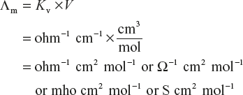
Hence, Λeq = Kv × V can be written as

Units

Hence,
![]()
5.3.5 Molar Conductivity
The molar conductivity of a solution is defined in a manner similar to that of equivalent conductivity. The term molar conductivity is sometimes also called as molar conductance or molecular conductivity. It is usually represented as Λm or μ.
The molar conductivity of a solution is defined as the conductance of all the ions produced from one mole of the electrolyte dissolved in V cm3 of the solution when the electrodes are one cm apart and the area of the electrodes is so large that whole of the solution is contained between them.
Similar to equivalent conductivity, molar conductivity is given by following expression as follows:
![]()
or

Units
5.3.6 Measurement of Electrolytic Conductance
As we know that conductance is the reciprocal of the resistance. Hence conductance can be obtained by the measurement of the resistance and resistance can be found by the principle of Wheatstone bridge method.
In finding the resistance of the solution of an electrolyte, a special type of cell has to be used such that the solution is present between the two electrodes. The cell thus used is called as conductivity cell. It consists of platinised Pt electrodes at a fixed distance apart and resistance is measured using alternating current to prevent any deposition on the electrodes during electrolysis as represented in Figure 5.3. In this process, an alternating current of frequency 500-2000 Hz is used. A signal generator such as a variable frequency oscillator, a null detector-indicator such as ear phone or a sensitive micro ammeter is used as a detector.

Figure 5.3 Wheatstone bridge circuit
Hence, Wheatstone bridge circuit consists of
- Source of alternating current which is either from induction coil or a vacuum tube oscillator.
- An earphone
- Platinised Pt electrodes
- Variable resistance with standard resistance box
In this method, a suitable value of resistance R is introduced from the standard resistance box such that when the sliding contact i.e., the Jockey J is moved along the stretched wire, the sound in the earphone is reduced to minimum at the point somewhere in the middle of the wire AB, say at the point C. Then if X is the resistance of the electrolytic solution, then by Wheatstone bridge principle,

Thus, knowing the resistance R and the balance point C, resistance X of the electrolytic solution can be calculated.
Hence,
![]()
To calculate specific conductivity, which is related with the conductance according to the expression
![]()
Thus specific conductivity of a solution can be determined by measuring its conductance and the distance (l) between the electrodes and area (a) of cross section of each of the electrodes.
For a particular cell, ![]() is constant and this constant is called as cell constant.
is constant and this constant is called as cell constant.
Hence,
![]()
Thus, the cell constant of any particular cell can be found by measuring the conductance of a solution whose specific conductivity is known. First of all we have to remove all types of organic as well as other oily impurities which are sticking to the walls of the cell and electrodes by cleaning with dilute chromic acid. Then we dipped the electrodes of the cell in ![]() KCl solution whose specific conductivity is known.
KCl solution whose specific conductivity is known.
By Kohlrausch it is verified that at 25 °C value of specific conductivity of ![]() KCl is 0.002765 ohm−1 cm−1. Hence by knowing the value of cell constant, the specific conductivity of the given solution can be determined by measuring its conductance and multiplying the value with the cell constant.
KCl is 0.002765 ohm−1 cm−1. Hence by knowing the value of cell constant, the specific conductivity of the given solution can be determined by measuring its conductance and multiplying the value with the cell constant.
Equivalent conductivity (Λeq) can be calculated by using the relation

Molar conductivity (Λm) can be calculated by using the relation
Hence, by knowing the molar concentration, C and specific conductivity K, Λeq (equivalent conductivity) and Λm (molar conductivity) can be calculated.
5.3.7 Variation of Conductivity with Concentration
As we know that, specific conductivity (K) as well as equivalent conductivity (Λeq) and molar conductivity (Λm) vary with the concentration of the electrolyte.
The specific conductivity K decreasing with increasing dilution (decrease in concentration) of the electrolyte solution while equivalent and molar conductance increases with increase in dilution (decrease in concentration) which is easily understood by the relation.
![]()
and
![]()
As mentioned above, equivalent conductance increases with increase in dilution and this value approaches to a limiting value as the dilution of the electrolytic solution increases. This limiting equivalent conductance value is called the equivalent conductance at zero concentration or infinite dilution Λ0 or Λα. With increasing dilution, dissociation of the electrolyte increases, hence equivalent conductance increases but the number of ions per unit volume decreases so specific conductance K decreases.
On the basis of an empirical relationship between the equivalent conductance and concentration given as
![]()
Where b is a constant depending upon the nature of the solvent.
Λ0 = specific conductivity at infinite dilution
This equation is called Debyl Huckel-Onsagar equation and is found to hold good at low concentrations.
5.3.8 Conductance Behaviour of Strong Electrolyte
In case of strong electrolyte, the equivalent conductance does not vary very much with dilution. A linear graph is obtained for low concentrations but it is not linear for higher concentrations. The curve shows that there is small increase in conductance with dilution. This is because a strong electrolyte is completely dissociated in solution and so the number of ions remains constant with increase in dilution, conductance increases and approaches a maximum limiting value at infinite dilution i.e., Λ0 or Λ∝.
Examples of strong electrolytes include strong acids and bases (NaOH, HCl, H2SO4, and KOH) and solutions of ionic solids (NaCl, KNO3, KCl etc).
5.3.9 Conductance Behaviour of Weak Electrolyte
In case of weak electrolyte, equivalent conductance increases rapidly with decrease in concentration. But conductance of a weak electrolyte is much lower than that of a strong electrolyte at the same concentration. Further the curve obtained for a weak electrolyte shows that there is a very large increase in conductance with dilution especially near infinite dilution as shown in Figure 5.4.
This is because as the concentration of the weak electrolyte is reduced, more of it ionizes. Thus, increase in conductance with decrease in concentration is due to the increase in the number of ions in the solution. However, it does not reach a limiting value, So Λ0 or Λ∝ cannot be determined graphically as in the case of strong electrolyte.
Examples of weak electrolytes include weak acids and bases (acetic acid, other organic acids and ammonia) and weakly dissociating salts.

Figure 5.4 Variation of equivalent conductance of a strong and weak electrolyte with electrolyte concentration

5.4 KOHLRAUSCH’S LAW OF INDEPENDENT MIGRATION OF IONS
The equivalent conductance of an electrolyte solution is equal to the sum of the conductivity of the constituent cations (λ+) and anions (λ−) and is expressed as
![]()
The equivalent conductance of an electrolyte solution increases with increasing dilution. At high concentrations, the greater inter-ionic attraction retard the motion of ions and therefore the conductance falls with increasing concentrations. But with decrease in concentration (increase in dilution) the ions are far apart and therefore the interionic attractions decreases due to which the conductance increases with dilution. So, at infinite dilution, the equivalent conductance reaches its maximum value as the retarding effects of the ionic atmosphere completely disappear.
![]()
Where ![]() and
and ![]() are called the ionic conductivities at infinite dilution for the cation and anion respectively and this equation is known as the Kohlrausch’s law of independent conductance of ions.
are called the ionic conductivities at infinite dilution for the cation and anion respectively and this equation is known as the Kohlrausch’s law of independent conductance of ions.
The equivalent conductivity of an electrolyte at infinite dilution is the sum of two values one depending upon the cation and the other upon the anion. This equation stated as at infinite dilution, each ion makes a definite contribution to the equivalent conductance of the electrolyte whatever be the nature of the other ion of the electrolyte.
In 1875, Kohlrausch made a series of measurement in which he observed that the difference between Λ° values for each pair of sodium and potassium salts having a common anion was same, irrespective of what this anion was. Similarly, the difference in the Λ° values for each pair of salts having the different anions and a common cation was same, irrespective of what this cation was.

The ionic conductivity values of some common ions at 25 °C is presented in Table 5.1.
Table 5.1 Ionic conductivities at infinite dution at 25 °C is in mho cm2

Applications of Kohlrausch’s Law
Conductance measurements have a wide range of numerous applications. A few of them are discussed below:
- Determination of equivalent conductivity at infinite dilution (Λ0) for weak electrolytes: As already mentioned, the equivalent conductivity of a weak electrolyte at infinite dilution cannot be determined experimentally, firstly because the conductance of such a solution is low and secondly because the dissociation of such an electrolyte is not complete even at very high dilutions. The equivalent conductivity at infinite dilution can be calculated using Kohlrausch’s law.
Consider the example of acetic acid (CH3COOH) as the weak electrolyte. By Kohlrausch’s law

This equation can be arrived at by knowing the molar conductivities at infinite dilution for the strong electrolytes KCl, CH3COOK and HCl as by Kohlrausch’s law

Hence, we required

- Determination of the degree of dissociation or ionisation of weak electrolyte:
According to Arrhenius theory of electrolytic dissociation, the increase in the equivalent conductivity with dilution due to the increase in the dissociation of the electrolyte and reaches upto a limiting value at infinite dilution. Thus if ΛC is the equivalent conductivity of a solution at any concentration and Λ0 is the equivalent conductivity at infinite dilution (i.e., zero concentration).
So,

The value of Λ0 for the weak electrolyte can be calculated by using Kohlrausch’s law.
- Determination of dissociation constant of a weak electrolyte:
Knowing the degree of dissociation (α), the dissociation constant (K) of the weak electrolyte at concentration (C) can be calculated using the formula:


Thus by knowing degree of dissociation (α), dissociation constant (K) can be easily calculated.
- Determination of ionic product of water:
It is found that ionic conductances of H+ and OH− at infinite dilution are

By Kohlrausch’s law

Specific conductance of pure water at 25 °C found to be,

Applying the formula,

Here, Kw is ionic product of water.
- Determination of solubility of sparingly soluble salts:
Salts such as AgCl, BaSO4, PbSO4 etc which dissolve to a very small extent in water are called sparingly soluble salts. As they dissolve very little, their solutions are considered as infinitely dilute. Further as their solutions are saturated, their concentration is equal to their solubility.
Thus, by knowing the specific conductance (K) and equivalent conductance (Λ) of such a solution, we have

Hence, Solubility

Since the solutions are extremely dilute, the conductance contribution of water is also considered. So we have to be subtracted the value of water from the total conductance.
Therefore

Where Kω is the specific conductance of pure water.
And value of Kω is 1.60 × 10⁻⁶ S cm−1 at 25 °C.
Ionic Mobility
The ionic mobility is defined as the velocity with which an ion moves under a potential gradient of 1 volt per cm in a solution.

Hence,
Units of ionic mobility:
In CGS system: cm2 s−1 v−1
In S.I system: m2 s−1 v−1
Ionic mobility at infinite dilution (u0) is related to ion conductance at infinite dilution λ0 and it is obtained by dividing the equivalent conductance of the ion by the Faraday.
i.e., Ionic mobility

Hence,

and

Where
 and
and  are the equivalent conductance of the cation and anion of the electrolyte.
5.5 CONDUCTOMETRIC TITRATIONS
Conductometric titration is a simple and accurate technique used in volumetric analysis to determine the end point of a titration.
Principle
Conductometric titration is based on the fact that the conductance of a solution at a constant temperature depends upon the following points:
- The number of ions present in solution
- Charge on the ions in solution
- Mobility of the ions present in solution
Conductance change during titration because in titration process one type of ions are replaced with other kind of ions which differ in their mobilities. At the end point, there is a sharp change in conductance.
Process
In this process, titrant is added from a burette into a solution taken in a beaker. Conductivity cell is dipped into this beaker by which conductance is measured after every addition of a titrant.
Conductance of a solution is plotted against volume of titrant added by taking conductance along y-axis and volume of titrant along x-axis.
Two straight lines are plotted and end point is the point of intersection of two straight lines.

Figure 5.5 Arrangement for conductometric titration
Types of conductometric titrations:
- Acid-base or neutralization titrations
- Displacement titrations
- Precipitation titrations and complexation titrations
- Acid-base titrations:
- Titration of a strong acid with a strong base:
Reaction between a strong acid (HCl) with a strong base (NaOH) is written as

By taking acid solution (HCl) in a beaker and base (NaOH) into the burette, conductance of 20 ml of HCl is measured with conductometer on every 1 ml addition of NaOH solution from the burette. A graph is plotted by taking volume of base along x-axis and conductance along y-axis.
From the graph, it is clear that conductance first decrease due to replacement of fast moving H+ ions with slow moving Na+ ions till the end point. After end point, conductance sharply increases due to presence of fast moving OH− ion in the solution.
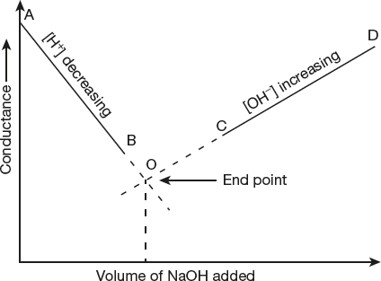
Figure 5.6 Titration curve of strong acid vs strong base
- Titration of a strong acid with a weak base:
The reaction between a strong acid with a weak base is written as

When a strong acid is titrated against a weak base, a graph as shown below is obtained.
From the graph, it is clear that conductance first decrease sharply due to replacement of fast moving H+ ions with slow moving NH4+ ions. After the end point, there is very small increase in conductance because of presence of weak base in the solution.

Figure 5.7 Titration curve for strong acid vs weak base
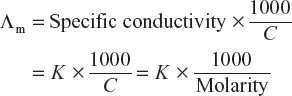
- Titration of a weak acid with a strong base:
The reaction between a weak acid with a strong base is written as

During titration of a weak acid with a strong base, a graph as shown below is obtained.
From the graph, it is clear that conductance first decrease due to formation of strong salt (CH3COONa) having a common ion effect (CH3COO–) which suppresses the ionization of weak acid. There is a small increase in conductance up to end point, due to formation of strong salt (CN3COO– Na+) which completely ionizes in the solution.
After the end point, conductance sharply increases due to presence of strong base (Na+OH–) in the solution.

Figure 5.8 Titration curve of weak acid vs strong base
- Titration of a weak acid with a weak base:
The reaction between a weak acid (CH3COOH) with a weak base (NH4OH) is written as

From the graph, it is clear that conductance first decreases due to formation of common ion (CH3COO–), which suppresses the dissociation of weak acid. Further increase in conductance up to end point is observed due to formation of strong salt (CH3COONH4) which completely dissociates into ions. After the end point, there is small increase in conductance due to presence of weak base (NH4OH) in the solution.

Figure 5.9 Titration curve of weak acid vs weak base
- Titration of a mixture of strong acid and weak acid with a strong base:
In such titrations of a mixture of strong acid (HCl) and weak acid (CH3COOH) with a strong base (NaOH), the graph obtained is shown hereunder.
When NaOH solution is added to the mixture of acids, the strong acid (HCl) is neutralized first due to high ionization.
Two end points ‘x’ and ‘y’ are obtained and point ‘x’ corresponds to neutralization of strong acid (HCl) with a strong base (NaOH).
Point ‘y’ corresponds to neutralization of weak acid (CH3COOH) with a strong base (NaOH).
After end point ‘y’, there is sharp increase in conductance due to presence of strong base (Na+OH–) in the solution.

Figure 5.10 Titration curve of strong and weak acid vs strong base
- Titration of a strong acid with a strong base:
- Displacement titrations:
Upon addition of HCl into sodium acetate (CH3COONa), displacement reaction taken place and is written as

From the graph, it is clear that there is small increase in conductance up to end point, which is due to replacement of highly dissociated CH3COONa with strongly dissociated NaCl and undissociated CH3COOH.
After the end point, conductance increases due to presence of HCl in the solution.

Figure 5.11 Displacement reaction of CH3COOH vs HCl
- Precipitation titrations:
Consider a precipitation reaction like AgNO3 vs KCl. The precipitation reaction is written as

From the figure, it is clear that conductance remains constant up to end point due to same mobilities of Ag+ and K+ ions. After the end point, there is a sharp increase in conductance due to presence of free ions (K+ and Cl−) in the solution.

Figure 5.12 Precipitation reaction of AgNO3 vs KCl
Advantages of Conductometric Titrations
- Conductometric titrations are more accurate.
- They can be used for titrating colored solution because the colored solutions cannot be titrated by ordinary volumetric methods using indicators.
- They can be employed even for titrating very dilute solutions.
- They can be used for titrating weak acids and weak bases.
- No observation is required near the end point because end point is detected graphically.
Limitations of Conductometric Titrations
- It can be applied only to a limited number of titrations.
- When the total electrolytic concentration is high, the results from conductometric titration become less accurate, less precision and less satisfactory.
5.6 ELECTROCHEMICAL CELLS
A device used to convert the chemical energy produced in a redox reaction into electrical energy is called an electrochemical cell or simply a chemical cell.
Electrochemical cells are also called galvanic cells or voltaic cell after the names of Luigi Galvani and Alessendro Volta, who were the first to perform experiments on the conversion of chemical energy into electrical energy. The galvanic cell consists of two half-cells combined in such a way that oxidation takes place in one beaker and reduction takes place in another beaker and both two electrodes are connected externally by a piece of metal wire and an electric current flows through the external circuit.
The practical application of galvanic cell is Daniel cell as shown in Figure 5.13. It consists of a zinc rod dipped in zinc sulphate solution taken in a beaker and a copper rod is placed in copper sulphate solution taken in another beaker. The two portions of the cells are called half cells or redox couples in which oxidation half reaction in one beaker and reduction half reaction in another beaker. The two electrodes are connected by a wire and two solutions are connected by a salt bridge.

Figure 5.13 Daniel cell
Salt bridge is an inverted U-shaped tube containing concentrated solution of an inert electrolyte like KCl, KNO3, K2SO4 etc., or solidified solution of such an electrolyte in agar-agar and gelatine. The inert electrolyte does not take part in the redox reaction. The main functions of the salt bridge are
- To complete the electrical circuit by allowing the ions to flow from one solution to the other without mixing of the two solutions.
- To maintain the electrical neutrality of the solutions in the two half-cells.
The oxidation and reduction reactions that occur at the two electrodes may be represented as:
At the anode:
![]()
At the cathode:
![]()
The overall cell reaction is:
![]()
or
![]()
Some important features of the electrochemical cell may be summed up as follows:
- The zinc electrode at which oxidation takes place is called the anode. The copper electrode at which the reduction takes place is called the cathode.
- Due to oxidation of zinc electrode, electrons are produced at the zinc electrode and it pushes the electrons into the external circuit and hence it is designated as negative pole. The other electrode required electrons for the reduction of Cu2+ into Cu. Therefore, it acts as the positive pole.
- The electrons flow from the negative pole to the positive pole in the external circuit and conventional current is flowing in opposite direction.
- The oxidation of zinc into ions produces excess of Zn2+ ions in the left beaker. Similarly, reduction of copper ions to copper leaves the excess of SO42− ions in the solution in the right beaker.
- To maintain electrical neutrality of the solution in the two beakers, the cations and anoins move through the salt bridge which helps to complete the inner circuit.
Representation of a Galvanic Cell
An electrochemical cell is represented in a manner as illustrated below for the Daniel cell:
![]()
or
![]()
- The electrode on which oxidation takes place is written on the left hand side and other electrode on which reduction takes place is written on right hand side.
- Anode is written by writting the metal first and then the electrolyte and cathode is written by first writing the electrolyte and then metal.
- Single vertical lines represent the phase boundaries of the electrodes and double line represents the salt bridge.
Electrode Potential
Consider a metal rod (M) placed in contact with a 1 M solution of its own ions (Mn+) at 25 °C, then there are possibilities such as
- The metal atoms of the metal rod (M) may lose electrons and changed into Mn+ ions, i.e., metal atoms get oxidized
 (1)
(1) - The Mn+ ions, on collision with the metal rod may gain electrons and changed into metal atoms i.e., Mn+ ions are reduced.
![]() (2)
(2)
What actually happens depends upon the relative tendency of the metal or its ions. If metal has relatively higher tendency to get oxidized then reaction (1) will occur. If the metal ions have relatively higher tendency to reduced, then reaction (2) will occur. During oxidation negative charge is developed on metal rod and during reduction positive charge develops on metal rod.

Thus in either case, there is a separation of charges between the metal rod and its ions in the solution. As a result, a potential difference exists between them.
“The electrical potential difference set up between the metal and its ions in the solution is called electrode potential or the electrode potential may be simply defined as the tendency of an electrode to lose or gain electrons when it is in contact with solution of its own ions”.
The electrode potential is termed as oxidation potential if oxidation takes place at the electrode with respect to standard hydrogen electrode and is called as reduction potential if reduction takes place at the electrode with respect to standard hydrogen electrode. The electrode potential is called standard electrode potential if metal rod is suspended in a solution of one molar concentration and the temperature is kept at 298 K.
Measurement of Electrode Potential
The absolute value of the electrode potential of a single electrode potential cannot be determined because oxidation half reaction or reduction half reaction cannot take place alone. It can only be measured by using some electrode as the reference electrode. The reference electrode used is the standard or normal hydrogen electrode (S.H.E or N.H.E).
It consist of platinum foil or wire coated with platinum black dipped into a molar (1M) solution of H+ ion and hydrogen gas at 1 atmospheric pressure is continuously passed through it at 298 K. This electrode may serve as anode or cathode depending upon the nature of another electrode to which it is connected.

The reaction, when electrode acts as the anode i.e., oxidation takes place
![]()
When this electrode act as the cathode i.e., reduction takes place
![]()
This electrode is usually represented as
![]()
The electrode potential of the standard hydrogen electrode is taken as 0.000 at 298 K. The standard electrode potential of the other electrode can be determined by connecting it with S.H.E and finding EMF of the cell experimentally. As the EMF of the cell is the sum of oxidation potential where oxidation takes place and reduction potential of the electrode where reduction takes place and as the electrode potential of S.H.E is zero, so EMF of the cell will directly gives the electrode potential of the electrode under investigation.
EMF or Cell Potential of a Cell
As we know that electrochemical cell is made up of two electrode i.e., two half cells. One of these electrodes must have a higher electrode potential than the other. As a result of this, the electrons flow from an electrode at a higher potential to the electrode at a lower potential.
The difference between the reduction potentials of the two half cells is known as electromotive force (EMF) of the cell or cell potential or cell voltage.

The EMF of the cell depends on
- The nature of the reactions
- Concentration of the solution in the two half cells reactions
- Temperature.
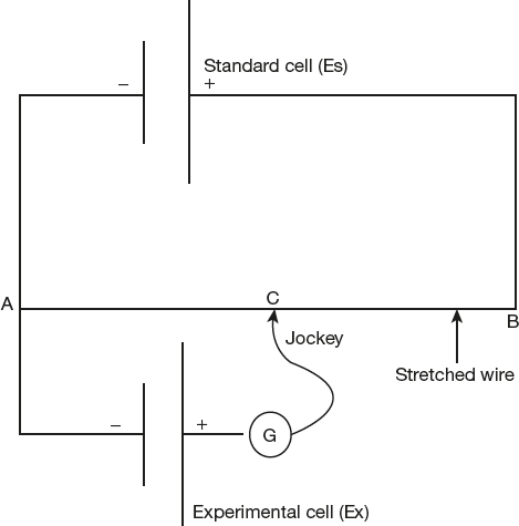
EMF Measurement
EMF of any electrochemical cell is determined by potentiometric method. The measurement becomes possible when the positive pole of the cell is connected to the end B of the potentiometer wire and the negative pole to the sliding contact. If the connections are wrong the balance point cannot be determined and hence the polarity of the electrodes is also indicated by the circuit. The emf of the cell (Ex) is measured by comparing with the emf of a standard cell (Es), Whose EMF is accurately known and remains constant at a given temperature.
The sliding contact jockey J is moved along the wire AB till there is no deflection (zero current flow) in the galvanometer (point C on the wire). The emf of the standard cell (Es) is proportional to the length AB and emf of the cell (Ex) is proportional to the length AC and the emf of the unknown cell Ex is calculated by the formula for no deflection in the galvanometer G.

Electrochemical Series
As we know that emf or cell potential or cell voltage can be calculated as
![]()
or
![]()
If the electrode potential or half - cell potential are measured at 25 °C (298K), then

In the Daniel cell,
![]()
Where E°Cu2+/Cu and E°Zn2+/Zn are the standard reduction potential for copper and zinc ion.
(Always remember that when no specific mention is made the electrode potential is always the reduction potential.)
“Electrochemical series is a series in which various electrodes have been arranged in order of their increasing values of standard reduction potential”. Electrochemical series as shown in Table 5.2.
Table 5.2 Electrochemical series

Applications of Electrochemical Series
- To compare the relative oxidizing and reducing powers:
In an electrochemical series, the species which are placed above hydrogen are more difficult to be reduced and their standard reduction potential values are negative. The Li, Li+ electrode has the least E° Value and therefore, it is reduced with most difficulty. Therefore, Li is the strongest reducing agent and the species which are placed below hydrogen are easily reduced and their standard reduction potential values are positive. The F2, 2F− electrode has the highest E°value and therefore, F2 has the greatest tendency to get reduced, so F2 is the strongest oxidizing agent.
- To compare the relative activities of metals:
Lesser the reduction potential of a metal, more easily it can lose electrons and hence greater is its reactivity. So, as a result, a metal with less reduction potential can displace metals with higher reduction potentials from their salt solutions.
For example, Reduction potential of Mg, Zn, Fe, Cu and Ag are in the order: Mg < Zn < Fe < Cu < Ag.
Hence, each metal can displace metals on its right from the salt solutions.
- To predict whether a metal reacts with acid to give hydrogen gas:
Metal (M) may react with an acid to give hydrogen gas (H2), the following reaction takes place.

Which can split into two half reactions as:

Thus, the metal should have the tendency to lose electrons i.e., undergo oxidation, w.r.t hydrogen so; the metal should have a negative reduction potential. Thus, all the metals above hydrogen in electrochemical series react with the acid to give hydrogen gas.
- To predict the spontaneity of any redox reaction:
For a spontaneous reaction, EMF of the cell must be positive and EMF can be calculated by using the formula.

- To determine the equilibrium constant:
As we know that

and

Therefore, by measuring of E° helps us to determine the equilibrium constant for the electrode reaction.
Nernst Equation for Electrode Potential
Nernst equation tells us the effect of electrolyte concentration and temperature on the electrode potential.
For this purpose, the electrode reaction is written as reduction reaction.
![]()
Since ΔG: −nFE and ΔG° = −nFE°
Hence

For pure solids or liquids or gases at one atmospheric pressure, the molar concentration is taken as unity

We get ![]()
In case of an electrochemical cell,
![]()
Then applying Nernst equation, we have

Where n is the number of electrons involved in the cell reaction.
5.7 TYPES OF ELECTRODES
Different types of single electrodes other than the one seen in Daniel cell are also presents in an electrochemical cell. Half cell reactions of such types of electrodes are discussed by using Nernst equation. Single electrodes may be grouped into the following types:
- Metal-metal ion electrode:
Such type of electrode consist of a pure metal (M) is dipped in a solution of its cation (Mn+)
The reaction may be represented as

Thus single electrode potential by Nernst equation is given by

Since [M] = 1 in pure solids or liquids form.
Hence,

Ex.: When Zinc rod is dipped in ZnSO4 or copper rod is dipped in CuSO4 soln.
- Metal-amalgam electrode:
Such type of electrode is set up when metal – amalgam (i.e., When metal dissolved in mercury to form metal – amalgam) is in contact with a solution of metal ion (Mn+). Generally, more active metals such as sodium metal is used for metal – amalgam solution.
The reaction may be represented as:

and electrode potential by Nernst equation

or

Where E°M/Mn+ is the standard potential of pure metal, [M(Hg)] is the activity of the metal in amalgam which is not unity.
- Metal-metal insoluble salt electrode:
Such type of electrode is set up when metal (M) is in contact with sparing soluble salt (MX) and dipped in a solution containing a common anion (X−).
The reaction is represented as

Electrode reaction as:

Electrode potential as by Nernst equation

Ex.: (i) Silver – silver chloride electrode in which silver metal is dipped AgCl solution and then KCl solution Ag|AgCl|Cl−.
(ii) Calomel electrode in which mercury is in contact with solid mercurous chloride and a solution of KCl.

- Gas electrode:
Such type of electrode is set up when inert metal (e.g. Pt) dipped in a solution containing ions to which the gas is reversible and then gas is continuously bubbled through the solution.
Example: Hydrogen electrode consist of a platinum wire coated with platinum black and dipped in a solution of H+ ions through which hydrogen gas is bubbled.
The hydrogen electrode is represented as

and electrode reaction is represented as

and electrode potential is given by

Since activity of [H2] = 1
So

We know that pH = −log[H+]
Hence

- Redox electrode:
Such type of electrode is set up when inert metal (e.g., Pt) dipped in a solution containing common ions in two oxidation states of the substance.
Example: When Pt wire is in contact with common ions in different oxidation state such as Fe2+ and Fe3+
Electrode is represented as

Electrode reaction is represented as

Electrode potential is given by

5.8 REFERENCE ELECTRODE
As we know that, each electrochemical cell is made up of two electrodes. It is not possible to determine experimentally the potential of a single electrode. Electrodes whose potentials are exactly known and can be used for the construction of the electrochemical cell and by which we can determine the single electrode potentials are called as reference electrodes.
The common examples of reference electrodes used include the standard hydrogen electrode (SHE), calomel electrode and silver-silver chloride electrode.
References electrode are broadly classified into two types:
- Primary reference electrode
- Secondary reference electrodes
- Primary reference electrode:
Standard hydrogen electrode (S.H.E) is used as a primary reference electrode because its standard potential is taken as zero at all temperature. But it is not always convenient to use standard hydrogen electrode because it is difficult to maintain the activity of H+ ions in the solution at unity and also to keep the pressure of the gas uniformly at one atmosphere.
So, for these reason, some secondary reference electrodes like Ag − AgCl, calomel electrode, Quinhydrone electrode etc. are used.
- Secondary reference electrodes:
They include Ag – AgCl electrode, glass electrode, calomel electrode, Quinhydrone electrode, their standard potentials are accurately determined and they are generally used in place of standard hydrogen electrode.
- Standard calomel electrode (SCE):
Calomel electrode is commonly used as a secondary reference electrode for potential measurements Calomel electrode consist of mercury, solid mercurous chloride and a solution of potassium chloride.
The electrode is represented as Hg, Hg2Cl2(s); KCl solution.
Construction of calomel electrode:
It consist of pure mercury (Hg) placed at the bottom of a glass tube having a side tube on each side. Mercury (Hg) is covered with a paste of mercurous chloride Hg2Cl2 (Calomel), as shown in diagram. After that a solution of potassium chloride (KCl) is placed over the paste through the right side tube and the solution is also filled along the left side also after that a platinum wire is dipped into glass tube to make electrical contact of the electrode with the circuit as represented in Figure 5.14.
Working of calomel electrode:
- If reduction occurs on calomel electrode then reactions may be represented as follows:

It results into increase in the concentration of chloride ions in solution.
- If oxidation occurs on calomel electrode then reactions may be represented as follows:
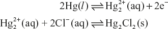

Figure 5.14 Saturated calomel electrode
It result into decrease in the concentration of Cl− ions and increase the
 ions in the solution.
Thus, in case of the calomel electrode, the electrode reaction is generally represented as

Electrode potential is given by

Thus, potential of calomel electrode depends upon the concentration of chloride Cl− ions.
The reduction potential of calomel electrode also varies with the concentration of KCl solution and reduction potential of the calomel electrode at 298 K for various KCl concentrations are on hydrogen scale are discussed below in Table 5.3:
Table 5.3 Electrode potential of KCl solution at different concentration at 298 K

To obtain the potential of any other electrode it is combined with the calomel electrode and the emf of the resulting cell is measured. By which we can easily measure the potential of other electrode.
Advantages
- Calomel electrode is simple to construct.
- It does not vary with temperature.
- It is stable for a long time.
- If reduction occurs on calomel electrode then reactions may be represented as follows:
- Quinhydrone Electrode:
This electrode is also used as a reference electrode. This is a redox electrode in which oxidation reduction takes place simultaneously.
It consists of a platinum wire dipped in a solution containing equimolar ratio of hydroquinone (QH2) and Quinone (Q).
The electrode reaction is represented as:

The electron is represented as

Hydroquinone is reversible with [H+] concn
The electrode potential at 298 K is given by

Since, concentration of Quinone and hydroquinone is unity because both are taken in equimolar ratio.

Hence,

As we know that

So,

Quinhudrome (QH2) is used for the measurement of the pH of the solution. This electrode is not suitable for alkaline medium
The standard electrode potential of the quinhydrone electrode,

Hence,

Thus potential of quinhydrone electrode, depends upon the pH of the solution.
- Standard calomel electrode (SCE):
5.9 ION SELECTIVE ELECTRODES (ISE)
An ion selective electrode consists of specially prepared membranes placed between two electrolytes and having the ability to respond to certain specific ions. So, it is also called as specific ion electrode (SIE). In such type of electrode the potential developed across the membrane which is related to the activities of the specific ion dissolved in a solution and this potential is measured by potentiometric device like a voltmeter or pH meter.
5.9.1 Electrochemical Circuit and Working of ISE
The ISE consist of a tube, in which one end of the tube is fused to an electrically conducting membrane and the tube contains a gel incorporating the ion to which the electrode is sensitive and inert electrolyte such as potassium chloride. A silver wire in contact with the gel together with the inert electrolyte constitutes the internal silver-silver chloride reference electrode. After that ion selective electrode is coupled to a SCE and immersed in sample solution. The potential difference developed across the membrane and this potential difference is related with the activity of ions present in gel as well as in sample solution as shown in Figure 5.15.

Figure 5.15 Electrochemical circuit
The cell is represented as

The potential difference developed across the membrane is given by
![]()
and emf of the cell is given by
![]()
- When same reference electrodes are used then ΔEref = 0
- When different reference electrodes are used then ΔEref = constant (k)
Suppose in a cell the reference electrode is cathode and so, ISE is cathode.
![]()
Here, k is a constant depends upon the internal and external reference electrode and C1 and C2 are the concentration of the external and internal solution respectively.
5.9.2 Types of Ion – Selective Membranes
There are four main types of ion – selective membranes used in ion selective electrode
- Glass membranes
- Solid state membranes/crystalline membranes
- Gas sensing membranes
- Liquid ion-exchange membranes
- Glass membranes:
The electrode which is having glass membrane is very highly selective for some cations such as Na+,
 , Ag+ and Li+ and also selective for some double-charged metal ions, such as Pb2+ and Cd2+.
Glass membranes are made from ion-exchange type of glass containing Na2O, CaO and SiO2 as shown in Figure 5.16(a).
- Solid state membranes/Crystalline membranes:
This type of membrane is selective for both cation and anion of the membrane forming substance.
This type of membrane is made up from lanthanum trifluoride (LaF3) Crystal doped with europium difluoride (EuF2) is sensitive for Fluoride F− ion and selectivity for other halides, cyanide, silver, lead, membranes is formed by pressing pellet with pure silver sulphide(Ag2S). For example, for chloride (Cl−) ion, pellet of (AgCl & Ag2S) is pressed together within membrane as shown in Figure 5.16(b).
- Gas sensing membranes:
The electrode having gas sensing membrane is used to measure the concentrations of dissolved gases such as carbon dioxide (CO2), ammonia (NH3), Sulphur dioxide (SO2) Nitrogen oxide (NO2) and oxygen (O2). Gas molecules diffuse across the membrane until the gas concentration are the same in the internal electrolyte and the sample solution. Any change in the gas concentration in internal electrolyte brings about a change in pH of the electrolyte and this pH is measured by glass electrode.
For example, The CO2 gas sensing electrode has a sodium hydrogen carbonate (NaHCO3) solution as the internal electrolyte and cell reaction is

The concentration of
 bicarbonate ion is considered as constant in the internal electrolyte. The pH of the glass electrode is a function of dissolved carbon dioxide in the sample solution.
 - Liquid ion-exchange membranes:
Such type of membrane is usually consisting of a large organic molecule capable of specifically interacting with an anions or cations.
For cations such as calcium dialkyl phosphoric acid in which calcium chloride is taken as an internal solution.
For alkali and alkaline earth metal cation, membrane is made up from phosphate diesters and neutral monocyclic crown ethers.
For anions such as
 membrane is made up from tris–1,10-Phenanthroline Fe2+(ClO−4)2
Figure 5.16 (a) Ion selective electrode of glass membrane

Figure 5.16 (b) Ion selective electrode of solid membrane and
(c) Ion selective electrode of liquid membrane
5.9.3 Applications of Ion Selective Electrodes
Ion selective electrodes have become extensively important in recent years, because of the fact that the potential of these electrodes solves a large number of practical problems. They have been widely used in clinical, biological, water, air, oceanographic and pharmaceutical research, and in general analytical determinations. These are commercially available and reliable for H+, NH3, F−, Cl−, Br−, I−, Cd2+, CN−, ![]() , Pb+2,
, Pb+2, ![]() , K+, Ag+, S2−, Na+, SCN−, SO2 and a variety of enzymes.
, K+, Ag+, S2−, Na+, SCN−, SO2 and a variety of enzymes.
The electrodes have been used for the following individual measurements and titrations:
- It is possible to determine lead poisoning in blood and urine samples by atomic absorption or ashing the sample and using a colourimetric reagent for the lead in the residue. Lead can be measured directly in blood or in urine samples with a PbS/Ag2S electrode. No pre-treatment or separation is required.
- Chloride ion can be determined in a variety of industrial and physiological samples by making use of chloride electrode. Rapid accurate clinical determination of Cl− ion in sweat is an example.
- The distillation and titration procedure in Kjeldahl method may be avoided by using ammonia electrode. Nitrogen is converted into
 ion and the solution is made basic and the concentration of NH3 is determined with ammonia electrode.
 - Calcium electrode has been used to determine Ca+2 ion in beer, boiler water, soil, milk, minerals, serum, sea water, sugar, wine, etc. Ca2+ is one of the most important electrolytes in human physiology. The determination of Ca+2 in biological fluids and related samples is, thus, very important.
Successful measurements of this type have been made with calcium ion exchange electrode and flow through electrode. The latter electrode is ideally suited for serum and other biological fluids because of increased selectivity of Ca2+ over Na+ and K+.
- The electrode has also been used for measuring stability constants of Ca2+ complexes and to follow the kinetics of complex formation.
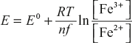
The potentials of each electrode can be expressed by the Nernst equation. For example, for a reaction

The Nernst equation may be written as

where E0 is the standard potential of the reaction recorded on the scale in which the normal hydrogen electrode is zero. [OX] and [Red] are molar concentrations of the oxidised and reduced species, respectively. Actually, activities should be used rather than concentration. However, for potentiometric titration close to the end point, activity charges are very close to the concentration charges, and hence, concentrations are used for simplicity.
5.10 GLASS ELECTRODE
Principle: pH of an aqueous solution depends upon the concentration of H+ ions and pH is determined by using glass electrode. When glass electrode is immersed in solution, whose pH value is to be determined, the potential difference develops across the membrane and this potential difference is proportional to the concentration of H+ ions.
5.10.1 Construction of Glass Electrode
The glass electrode consists of an electrically conducting glass membrane which is made up from Na2O, CaO and SiO2. Glass electrode taken in the form of bulb and then sealed to the bottom of a glass tube as shown in Figure 5.17. The bulb contains 0.1 M HCl solution and internal reference electrode such as Ag-AgCl electrode or platinum wire is dipped in solution to make electrical contact with the solution. Electrode is represented as
![]()

Figure 5.17 Glass electrode
Theory
The glass membrane of glass electrode undergoes on ion-exchange reaction with the Na+ ions of the membrane with H+ ions.
![]()
The potential difference developed across the gel layer of glass membrane between the two liquid and this potential difference developed due to the concentration (C1) of acid solution inside the bulb and concentration (C2) of acid solution into which glass bulb is dipped.
![]()
As we known that C1 = 0.1M
![]()
As we know that pH = −log[H+]

For the measurement of pH of any unknown solution, the glass electrode is immersed in that solution, and then it is combined with a reference saturated calomel electrode.
The electrochemical cell is represented as
Ag |AgCl|0.1 MHCl| Glass |Solution of unknown pH| saturated calomel electrode
EMF of the cell at 298 K is given as

EMF of calomel electrode at standard condition is

The value of ![]() is obtained by measuring with the solution of known pH and EMF of such a cell is determined by a potentiometer. So, we can easily determine the pH of unknown solution cell arrangement is represented in Figure 5.18 for unknown solution.
is obtained by measuring with the solution of known pH and EMF of such a cell is determined by a potentiometer. So, we can easily determine the pH of unknown solution cell arrangement is represented in Figure 5.18 for unknown solution.

Figure 5.18 Glass electrode-calomel electrode cell arrangement for pH determination
Advantages of Glass Electrode
- It can be used even in strong oxidising solutions as well in alkaline solutions.
- The results obtained are quite accurate.
- It is simple to operate and most convenient.
- It is not easily poisoned.
- pH is easily determined with few milliliters of solutions.
- It can easily used in the presence of metallic ions.
Limitations of Glass Electrode
The glass electrode is sensitive zeta ions such as Na+ in addition to H+, particularly at pH > 9 which result into the alternation of the linear relationship between pH and EMF of the glass electrode.
5.11 CONCENTRATION CELL
In concentration cell, EMF arises due to transfer of matter from one half-cell to the other because of a difference in the concentration of the species involved in two half-cell.
Concentration cells may be classified into two types
- Electrode – concentration cells
- Electrolyte – concentrations cell

- Electrode concentration cells:
These cells consist of two like electrodes at different concentration are dipping in the same solution of the electrolyte. For example, two hydrogen electrodes at different gas pressures immersed in the same solution of hydrogen ions constitute an electrode – concentration cell.
This cell is represented as

electrode reaction is represented as,
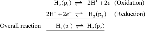
According to nearest equation, EMF of the cell is 25 °C is given by
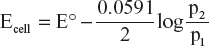
E° for concentration cell is zero

The process is spontaneous when expansion of hydrogen gas from pressure p1 at one electrode to pressure p2 at the other electrode it means p2 < p1.
Another example of such type of cell is that of an amalgam with same metal at two different concentrations.

The electrode reaction is written as:

EMF of the cell is given by

If C1 > C2, then EMF is positive, it means the whole process is spontaneous.
- Electrolyte-concentration cells:
In these types of cells two identical electrodes are dipped in two metal ions solution at different concentration.
Such type of cells is represented as

Example:

Here C1 and C2 are the concentration of metal ion (Mn+) in the two electrolyte and these two electrolytes are separated from each other by salt bridge and C2 > C1 for a spontaneous process.

EMF of the cell

If (i) C1 = C2

(ii) C2 > C1, EMF of the cell comes out to be positive, it means reaction is spontaneous in nature.
For example:

The cell reaction is

EMF of the cell

5.12 POTENTIOMETRIC TITRATIONS
Potentiometric titrations are those in which EMF of any cell is determined by plotting a graph between variation of electrode potential versus volume of titrant added.
They are generally are of three types:
- Acid-Base titrations
- Oxidation-Reduction titrations
- Precipitation titrations
- Acid-Base titrations:
For determining the strength of acid solution, we want to titrate a solution of HCl against NaOH. Any type of electrode whose electrode potential is depends upon the concentration of H+ ions (e.gs, quinhydrone electrode, glass electrode) is dipped in the HCl solution and then that electrode is connected with a reference electrode (e.g calomel electrode, Ag–AgCl(S) electrode) to form a electro chemical cell.
For example, suppose hydrogen electrode is used as H+ indicating electrode and a saturated calomel electrode is used as the reference electrode and then both electrodes are dipped in acid solution which is taken in beaker.
The electrochemical cell is represented as

EMF is measured by potentiometer which is connected to both the electrodes during the addition of alkali solution from a burette.

By knowing the EMF of the cell, we can determine the pH of the acid solution.
During the titration i.e., when we titrating acid solution (HCl) with titrant (alkali solution NaOH), concentration of H+ ion goes on decreasing i.e., pH of the solution goes on increasing. Hence according to equation-1 EMF of the cell goes on increasing. After that a graph is plotted against electrode potential versus volume of alkali (NaOH) added and we obtained a sigmoid curve in which end point is analysed. The titration curve is steep near the end point.

Figure 5.19 Potentiometric acid-base titration curve
As it is clear from the Figure 5.19 that for accurate determination of end point, curve should be steep near the end point, more accurately we can determined the end point by plotting a curve between
 versus volume of NaOH added and end point is determined by drawing a vertical line from the peak to the volume axis as shown in Figure 5.20.
Figure 5.20 Determination of end-point in acid-base titration curve
- Oxidation-reduction titrations:
The redox titrations are also carried out potentiometrically same as in acid-base titrations. In redox titrations electrode reversible with respect to H+ ions is replaced by an inert metal, such as Pt wire, immersed in a solution containing both the oxidized and reduced form of the same species.
The electrode acts as an oxidation-reduction electrode and this electrode is combined with a reference electrode, e.g., a saturated calomel electrode (SCE) to form a galvanic cell.
The cell is represented as

The EMF of the cell is measured potentiometrically at each stage of titration and end point is obtained near the steep point of the curve as in case of acid-base titration curve.
- Precipitation titrations:
In such type of titrations, potential of the half-cell is measured by connecting it with the calomel electrode. For example, precipitation reaction of silver nitrate (AgNO3) with potassium chloride (KCl)

Silver electrode is connected with the calomel electrode and silver nitrate (AgNO3) placed in the micro burette and potassium chloride (KCl) in the beaker and emf of the cell is measured and plotted against the volume of silver nitrate added. The steep rise in the curve shows the end point of the titration same as in acid-base titration curve.
5.13 ELECTROCHEMICAL SENSORS
Electrochemical sensors are devices which are used to measure electrical parameters such as potential difference, current, conductance etc., of the sample under analysis.
The sensor which is measure the potential difference is called potentiometric sensor and which measure current is called amperometric sensor.
Electrochemical sensors produces an electrical signal which is related to the sample under study.
Biological processes such as analysis of glucose in blood and urea are analysed by potentiometric or amperometric sensor.
5.13.1 Potentiometric Sensor
A potentiometric sensor is a type of chemical sensor which measure potential difference of an electrode when there is no current flow.
Principle
Potentiometric sensor is used to determine analytical concentration of gas or solution. Working electrode and the reference electrode gives potential difference which is measured by potentiometer.
In the potentiometric sensor the ion-selective electrode (ISE) is coupled with the reference electrode to complete electrical circuit and the sensor measured the potential difference between two electrodes is shown figure.

Glass electrode is used to measure pH of the solution taken as ion-selective electrode and connected with reference electrode.
5.13.2 Analysis of Glucose in Blood
For analysis of glucose in blood glucose sensor which is a potentiometric sensor is used.
Glucose is converted into ions, which is detected by ion-selective electrode (ISE). Glucose is oxidised into gluconic acid which further undergoes decomposition and gives H+ ions which are detected by pH electrode.
The reaction can be written as
![]()
Formed H2O2 undergoes reaction at the electrode as shown below
![]()
H+ ions is measured by pH meter i.e, glass electrode and a potential difference is set-up between glass electrode and reference electrode which is sense by potentiometric sensor which analyse the glucose level in blood.
5.13.3 Analysis of Urea
Analysis of urea in serum or urine sample is very common. For this analysis, enzymatic potentiometric sensor or urea bio sensors is used.
Urea concentration is determined during enzymatic reaction of urea with urease which release ![]() ions and
ions and ![]() ions. By using ammonium ion-selective electrode analyse the ammonium ions (
ions. By using ammonium ion-selective electrode analyse the ammonium ions (![]() ) concentration.
) concentration.
![]()
Electrode is modified with a gel containing the urease enzyme. The signal is determined by potentiometric bio sensor which sense the presence of urea in different sample.
5.14 VOLTAMMETRY
Amperometry is an electrochemical technique in which a current is measured as a function of an independent variable, that is, time or electrode potential. Voltammetry is a sub-class of amperometry in which current is measured by varying the potential applied to the electrode. Polarography is a sub-class of voltammetry that uses a dropping mercury electrode as the working electrode. Coulometry uses applied current or potential to completely convert an analyte from one oxidation state to another. In these processes, the total current passed is measured directly or indirectly to determine the number of electrons passed. Potentiometry measures the potential of a solution between two electrodes. Here, one electrode is used as a reference electrode; it has the constant potential, and the other is used as an indicator electrode, whose potential changes depend on the sample.
Electroanalytical methods that depend on the measurement of current as a function of applied potential are called voltammetric methods. Voltammetry comprises a group of electroanalytical methods that are based upon the potential current behaviour of a polarizable electrode in the solution being analysed. In voltammetry, a measured small potential is impressed across a pair of electrodes one of which is a non-polarizable reference electrode and the other a polarizable inert electrode. The current, which flows, depends upon the composition of the solution. In other words, voltammetry and voltammetric analysis are concerned with the study of current voltage relation at a micro electrode called working electrode. In order to ensure polarization of the electrode, its dimensions generally are made small. Therefore, electrode may be of some inert metal, such as platinum or gold. A three-electrode cell is, however, preferred in general voltammetry. The third electrode can be a simple wire of platinum or silver or mercury pool. The reference electrode may be of any convenient form since it does not carry current (Figure 5.21).
Several voltammetric techniques such as Linear sweep voltammetry, Staircase voltammetry, Square wave voltammetry, Cyclic voltammetry, Anodic stripping voltammetry, Cathodic stripping voltammetry, Adsorptive stripping voltammetry, Alternating current voltammetry, Polarography, Rotated electrode voltammetry, Normal pulse voltammetry, Differential pulse voltammetry, and Chrono-amperometry play their own importance roles.
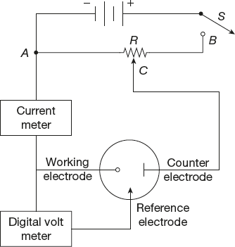
Figure 5.21 Voltammetric instrument
5.14.1 Linear Sweep Voltammetry (LSV)
The effectiveness of this technique is based on its capability for observing the redox behaviour rapidly over a long potential range. Since a rapid linear sweep of the potential is employed, the technique is commonly termed as linear sweep voltammetry (LSV) or stationary electrode voltammetry (SEV). Only stationary or quasi-stationary electrode like dropping mercury electrode is employed as the indicator electrode in an unstirred solution.
During the early period, such fast-scan rates could only be monitored over a cathode-ray oscilloscope; therefore, the LSV was then known as cathode-ray polarography. Now-a-days, fast-scan rate X-Y recorders can be used during such experiments. LSV is usually applied at a mercury drop or at any solid stationary electrode, wherein the potential scan rate can be moderate to fast. When a DME is used, the entire potential range is covered on a single drop. Since the sweep rate is fast as compared to drop-time, the recording is made during the end period of the drop’s life. This is done to minimize the condenser or charging current component. It also ensures that the growth of the mercury drop during the sweep period remains negligible.
In the single-sweep method, the potential of the working electrode increases linearly to a fixed value. It may then fall instantaneously to its starting value. The potential sweep has the appearance of a saw-tooth. The entire i-E curve is recorded during the linear rise of the applied potential. Due to fast potential sweep, there occurs a depletion of the depolarizer around the electrode surface and a peak-shaped i-E curve is recorded. The potential of the peak is characteristic of the depolarizer and its length on the current axis is proportional to concentration of the depolarizer. The following relation holds good for a reversible system.
![]()
Where Ep is the peak potential, E1/2 is the equivalent de polarographic half-wave potential and n the number of electrons taking part in the electrode reaction. The positive sign holds for the anodic reaction, whereas the negative sign holds for cathodic reaction.
Linear sweep voltammetry has been employed both for qualitative and quantitative analyses. It has a reasonably low detection limit, which goes down to 10−5 m. The sensitivity is improved by increasing the scan rate. LSV, being a transient technique, was earlier known as chronoamperometry with potential sweep since the potential axis may be taken as time axis.
During periodic polarization (multi-sweep), a saw-tooth voltage is applied with delay. A controlled drop-time is ensured with a DME.

Figure 5.22 A triangular excitation signal applied in cyclic voltammetry
5.14.2 Ferric Fe3+/Fe2+ System
Unlike potential step measurements, in LSV measurements, the current response is plotted as a function of voltage rather than time.
![]()
For the abovementioned system, if an electrolyte solution containing only Fe3+, then the following voltammograms would be seen for a single voltage scan.

Figure 5.23
The scan begins from left-hand side of the current/voltage plot where no current flows. As the voltage swept further to more reductive values, that is, towards right, a current begins to flow and reaches a peak before dropping.
To justify this behaviour, we need to consider the influence of voltage on the equilibrium established at the electrode surface. The rate of electron transfer is fast in comparison to the voltage sweep rate in electrochemical reduction of Fe3+ to Fe2+.
An equilibrium is established identical to that predicted by thermodynamics at the electrode surface.
Nernst Equation
Nernst equation can explain the relationship between concentration and voltage or potential difference.
Where E = Applied potential difference, E0 = Standard electrode potential.
Hence, when the voltage swept from V1 to V2, the equilibrium position shifts from V1 (no conversion) to V2 (full conversion) of the reactant at the electrode surface. The exact form of the voltammogram can be justified by considering the voltage and mass transport effects.
When the voltage is initially swept from V1, the equilibrium at the electrode surface begins to alter and the current begins to flow in the following ways:
The current rises as the voltage is swept further from its initial value as the equilibrium position is shifted further to the right due to conversion of more reactant. The peak occurs, and at the same point, the diffusion layer has grown sufficiently above the electrode so the flux of reactant to the electrode is not fast enough to satisfy Nernst equation. In this situation, the current begins to drop just as it is in the potential step measurement. The drop in current follows the same behaviour, which can be explained by Cottrell equation.
The above voltammogram recorded at a single scan rate. If the scan rate alters the current, then the response also changes. Figure 5.24 shows a series of linear sweep voltammograms recorded at different scan rates for an electrolyte solution containing only Fe3+.

Figure 5.24
Each curve has same form except total current. Here, total current increases with increasing scan rate. This again can be justified by considering the size of the diffusion layer and the time taken to record the scan. If the scan rate decreases, then LSV voltammogram will take longer time to record. The size of the diffusion layer above the electrode surface will be different depending on voltage scan rate. The diffusion layer will grew much further from the electrode in slow voltage scan when compared to fast scan. Hence, the flux to the electrode surface is smaller at slow scan rate than fast scan rate.
“Current is proportional to the flux towards the electrode and the magnitude of the current will be lower at slow scan and higher at high scan rate”.
“The position of the current maximum peak occurs at the same voltage; this is the important characteristics of electrode reaction which have rapid electron transfer kinetics and also often referred to as reversible electron transfer reaction”.
If the electron transfer processes were slow relative to the voltage scan rate, then the reactions are known as quasi-reversible or irreversible electron transfer reactions. Figure 5.25 represents a series of voltammograms recorded at a single-voltage sweep rate for different reduction rate constants.

Figure 5.25
In this kind of situations, the voltage applied will not result in the generation of concentrations at the electrode surface according to the Nernst equation. As the kinetics of the reaction is slow, the equilibria are not established rapidly according to voltage scan rate. In this kind of situation, the overall voltammogram recorded is similar to the graph shown in Figure 5.25, but unlike reversible reaction, the position of the current maximum shifts depending on the reduction rate constant and the voltage scan rate. This is due to the reason that current takes more time to respond to the applied voltage than the reversible case.
5.14.3 Cyclic Voltammetry
Cyclic voltammetry is a very versatile and useful technique and is ideal for studying the mechanism of redox reactions of diffusion coefficients and half-cell potentials. Actually, it is a logical extension of LSV. In cyclic voltammetry, a triangular potential wave is impressed on a solid indicator electrode. Therefore, both forward and reverse reactions are monitored, and complete current-potential characteristics of a redox system are supplied.
On repeating the triangular potential excitation signal during cyclic voltammetry, the potential of the electrode charges back and forth between two fixed values. These are known as the switching potentials. During a positive scan, the potential becomes increasingly positive, whereas the reverse is known as a negative scan. For recording the cyclic voltammogram, the resulting current is plotted during the positive and negative potential scans.
The cyclic voltammogram of a reversible system is shown in Figure 5.26. Here, reduction occurs during the negative scan and the reduced product is oxidized back during the positive scan. The cathodic and anodic peak heights appear equal in a reversible system. The nature and shape of a cyclic voltammetry curve is altered, if the reaction is accompanied by adsorption. Cyclic voltammetry is, thus, useful in diagnosing the mechanism of the electrode reactions. It also enables one to detect unstable intermediates of electrode reaction.

Figure 5.26 A typical cyclic voltammogram
In a reversible system, the difference between anodic and cathodic peak potentials is expressed by the following expression at 25°C.
![]()
A reversible redox couple can be identified from its cyclic voltammogram by measuring the potential difference between the two peaks. The mean between the two peak potentials will correspond to the formal electrode potential (E°) of the redox couple.
When the potential scan rate (V) is increased, both (ip)anodic and (ip)cathodic increase in proportion to V1/2. A plot of (ip)a and (ip)c versus V1/2 is linear for a reversible system.
The ratio of (ip)a/(ip)c remains unity and independent of the scan rate for a reversible couple with no kinetic complications. This ratio is influenced by coupled chemical reactions and such behavioural study makes cyclic voltammetry a very powerful tool for studying electrode reactions and their mechanisms.
The spacing between the two peak potentials is larger with irreversible systems as compared to reversible systems. With increasing irreversibility, the peaks get rounder, and finally, one of them disappears. The difference between the two peak potentials (ΔEp) is used to calculate the heterogeneous charge transfer rate constant after changes occur in the shape of CV on repeating.
The greatest utility of cyclic voltammetry is its ability to generate a species during a potential scan and then study its fate in the subsequent scan(s).
5.14.4 Applications of Voltammetry
Modern voltammetric methods continue to be potent tools used by analytical, inorganic, physical and biological chemists for fundamental studies of oxidation and reduction processes in various media, adsorption processes on surfaces and electron transfer mechanisms at chemically modified electrode surfaces.
Several types of voltammetry in current use are as follows:
- Voltammetric sensors have lot of importance in the determination of specific species that are of interest in industry and research; these devices are sometimes called electrodes but are in fact complete voltammetric cells and are better referred to as sensors.
- Stripping voltammetry is a significant trace analytical method, particularly for the determination of metals in the environment.
Anodic stripping voltammetry is a quantitative, analytical method for trace analysis of metal cations. The analyte is deposited (electroplated) onto the working electrode during a deposition step and then oxidized during the stripping step. The current is measured during the stripping step.
Cathodic stripping voltammetry is a quantitative, analytical method for trace analysis of anions. A positive potential is applied, oxidizing the mercury electrode and forming insoluble precipitates of the anions. A negative potential then reduces (strips) the deposited film into solution.
- Differential pulse polarography and rapid scan voltammetry are important for the determination of species of pharmaceutical interest.
- Polarography is a sub-class of voltammetry where the working electrode is a dropping mercury electrode (DME), useful for its wide cathodic range and renewable surface.
- Voltammetry and other electrochemical detectors are frequently employed in high-performance liquid chromatography and capillary electrophoresis.
- Amperometric techniques are widely used in sensor technology, monitoring titrations and reactions of biological interest.
- Adsorptive stripping voltammetry is a quantitative, analytical method for trace analysis. The analyte is deposited simply by adsorption on the electrode surface (i.e., no electrolysis) and then electrolyzed to give the analytical signal. Chemically modified electrodes are often used.
- Rotated electrode voltammetry is a hydrodynamic technique in which the working electrode, usually a rotating disk electrode (RDE) or rotating ring-disk electrode (RRDE), is rotated at a very high rate. This technique is useful for studying the kinetics and electrochemical reaction mechanism for a half-reaction.
5.15 BATTERIES
A battery is a device in which numbers of electrochemical cells are connected in series. It converts chemical energy into electrical energy at a constant voltage.
Batteries are generally used at a commercial level.
5.15.1 Advantages of Batteries
- In batteries, there is no need to be connected to an electrical system.
- Batteries act as a portable source of energy.
- Batteries can be easily replaced.
- Different types of batteries have their specific applications e.g. miniature batteries (primary cell) is generally used in electric watches, calculator, medical devices and secondary cells are generally used in portable equipments like portable radio and TV, mobile phones, lap–top, computers etc.
5.15.2 Disadvantages of Batteries
- Batteries can be used for only a limited time, even rechargeable batteries can be recharged a certain number of times.
- Some batteries are dangerous and can lead to fire, explosion, chemical pollution etc.
- Some types of batteries need to be maintained and checked periodically.
Requirements should be Possessed by the Batteries
- It should have the compactness, lightness and ruggedness for portability.
- Long life cycle is required.
- Operating voltage is required i.e., voltage should not drop much during use.
- It should be stable with time, temperature, vibration shock etc.
Classification of Various Commercial Cells
- Primary cells
- Secondary cells
- Fuel cells
- Primary cells: Primary cells are those in which redox reaction occurs only once and cell becomes dead after some time.
These are non-rechargeable and cell becomes dead after some time.
For example: dry cell, mercury cell and lithium cell etc.
- Secondary cells: Secondary cells are those which can be recharged by passing an electric current through them and hence can be used over and again.
For example: Lead storage cell, Ni – Cd storage cell etc.
- Fuel cells: Fuel cells are those in which the energy produced from the combustion of fuel such as H2, O2, CH4 etc. is directly converted into electrical energy.
A Brief Description of Example of Each Type of Cell
- Primary Batteries
- Dry cell:
Dry cell is a compact form of the Leclanche cell. This is also known as carbon – zinc cells.
It consists of a cylindrical zinc container which acts as the anode. A graphite rod placed in the center acts as the cathode. Dry cell does not use any liquid that’s why it is called as dry cell.
It consists of a mixture of NH4Cl, ZnCl2 and MnO2 made into a paste by the addition of starch which acts as electrolyte. The zinc container is covered with cardboard to protect it from the atmosphere as shown in Figure 5.27.
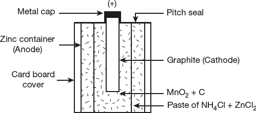
Figure 5.27 The dry cell
The reactions of the cell are:
At anode:

At cathode:

Overall reaction:

The NH3 formed is combined immediately with the Zn2+ ions and Cl− ions to form the complex salt [Zn (NH3)2Cl2]

The dry cell gives a voltage of about 1.5 V. The dry cell is generally used in flash lights, calculators, toys etc.
- Lithium cells:
Lithium cells are primary (disposable) batteries. Lithium cells have lithium metal as anode comprising many type of cathodes and electrolytes. Lithium cells are safer, less expensive, and non-toxic and meet the needs of present as well as future generation.
Due to its high electrode potential, it can produce voltages from 1.5 V to about 3.7 volt, which is twice the voltage of an ordinary battery.
Lithium cells are generally used in portable consumer electronic devices like radios, clocks, MP3 players, hearing aids, heart pacemakers etc.
Lithium cells can be classified into three categories:
- Lithium cells with solid cathodes
- Lithium cells with liquid cathodes
- Lithium cells with solid electrolyte
- Lithium cells with solid cathodes:
These cells use solid cathode materials such as MnO2, CuO, V2O5 and carbon monofluoride (CF)n. They cannot be discharged as rapidly as liquid cathode cells. Most commonly lithium batteries in use are of the Li|MnO2 type. Due to its low discharge characteristic it is generally suitable for memory backup, watches, calculators, cameras, etc.
The Li|MnO2 cell gives a voltage of about 3.2 V and it is capable to perform at low or high discharge rates on pulse and perform at wider range of temperature of the cell. It has a shelf life of around 5–7 years.

Cell reaction

Oxidation of lithium metal at the anode takes place which produce positively charged lithium ions (Li+) and electrons (e−). The Li+ ions go into the solutions and diffuse through electrolyte and electrons (e−) reach at the cathode where MnO2 is reduced from tetravalent to trivalent state.
- Lithium cells with liquid cathodes:
In these cells, the cathode material is reduced during discharging is present in the liquid form. Examples are
- • SO2 dissolved in a solution of Lithium bromide and acetonitrile
- • Liquid thionyl Chloride (SOCl2) as a solvent with lithium aluminium chloride as solute.
It is incompatible with standard batteries, that why they are mostly used for military applications such as munitions, transceivers and surveillance equipments. This type of cells gives a voltage of about 2.8 V to 3.5 V for different systems. It has a shelf life about 10 years at normal and cooler temperature.
- In Li-SO2 cell
Anode: Lithium metal
Cathode: SO2
Electrolyte: Lithium bromide and small amount of acetonitrile
There is a liquid cathode; it forms a protective layer at the interface of the lithium and SO2. To maintain the SO2 in a liquid form, Li–SO2 cells internal pressure is 3 bars at +20 °C temperature and 14 bars at +70 °C temperature.
Overall reaction

- In Li–SOCl2 cell
Anode: Lithium metal
Cathode: SOCl2
Electrolyte: LiAlCl4 (lithium terachloro aluminate)
In this, porous carbon material acts as a cathode current collector which receives electrons from the external circuit. It is not sold in the consumer market but having more application in industrial as well as military level.
Thionyl chloride is a corrosive liquid and reacts with lithium to produce LiCl, S and SO2. LiCl is precipitated on carbon electrode and SO2 and S are soluble in electrolyte, at lower depth of discharge.

Due to incomplete protective layer at surface of lithium, additives are used. It provides a voltage of around 3.5 V. It has poor shelf life.
- Lithium cells with solid electrolyte:
In such type of cell, solid such as lithium iodide (LiI) {which are electronic insulators but ionic conductors} can be used as the electrolyte in solid electrolyte batteries. Such batteries have extremely long shelf life at low drain currents or even at high temperature.
Such types of cells are generally used in heart pacemakers, and for preserving volatile computer memory.
Anode: Li metal
Cathode: Poly-2-vinyl pyridine (p2vp)
Electrolyte: Solid LiI (In situ)/ I2 (iodine)
There is a solid electrolyte and it provides a voltage of around 2.8 V. LiI is formed in situ by direct reactions of the electrodes.
Overall reaction

It is suitable only for low-current application and its voltage decreases with degree of discharge due to precipitation of lithium iodide. It has very low self–discharge voltage.
- Dry cell:
- Secondary batteries:
- Lead-acid cells: or (Lead storage cell)
This type of cells is called as storage battery or a storage cell. A storage cell is that which can work both as voltaic cell as well as electrical cell. During its operation it works as a voltaic cell i.e., it supplies electrical energy due to a chemical energy and it becomes discharged. Then during its charging, it works as an electrolytic cell i.e., chemical is produced by supplying of electrical energy. It is also called as lead storage battery.
It consist of

A lead storage battery consists of 6 cells each producing 2V output. To increase the current output of each cell, the cathode plates are joined together and the anode plates are also joined together and connected in series, we get an output of 12V as shown in Figure 5.28.

Figure 5.28 Lead storage battery
Electrode reactions during discharge
At anode: Lead (Pb) undergoes oxidation

The Pb2+ ions combine with
 (H2SO4) ions to produce PbSO4
At cathode:
Lead Oxide (PbO2) undergoes reduction due to flow of electrons from anode to cathode

and the Pb2+ ions combines with
ions to produce PbSO4
Overall reaction

Electrode reaction during charging
The lead storage battery is rechargeable. Now the cell is operated like an electrolytic cell.
The following reactions occur during charging:
At Anode:

At Cathode:

Overall reaction:

The PbSO4 formed during discharge is a solid and sticks to the electrodes. So, it is in position to gain or receive the electrons during electrolysis.
Such type of cell is generally used for electrical vehicles, Automobiles, railway, laboratories, hospitals, power stations, in telephone exchange, UPS system etc.
- Ni-Cd Storage cell (or NiCad cell):
This is also rechargeable cell which is generally used in calculators. It has a longer life than lead storage cell.
It consist of

Normally Ni-Cd cells have a potential of 1.2V and by using six cells, a voltage of 7.2V can be produced.
Electrode reactions during discharge
At Anode:

At Cathode:

Overall Reaction:

During recharge, the reactions go from right to left. The alkaline electrolyte (KOH) is not consumed in this reaction.
Such types of cells are used in cordless and wireless telephones, emergency lighting, remote controlled electric model airplanes, boats, and cars etc.
- Lithium ion cells:
Lithium ion batteries (sometimes abbreviate as Li-ion batteries) are a type of rechargeable battery in which the cathode (positive electrode) contains lithium and the anode (negative electrode) is generally made of a type of porous carbon.
During discharging, the current flows within the battery from the anode to the cathode; the internal process is the movement of Li+ ions from anode to the cathode, through the non-aqueous electrolyte.
During charging, an external power source, the current to pass in the reverse direction. The positive terminal of the charging circuit is connected to the cathode of the battery and negative terminal is connected to the anode.
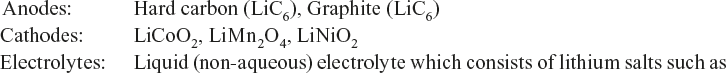
LiPF6, LiBF4 in an organic solvent, such as ethylene carbonate.
The cathode half reaction

The Anode half reaction

In Lithium-ion battery the lithium ions are transported to and from the cathode or anode, with the transition metal, Co in Li1-xCoO2 being oxidized from Co3+ to Co4+ during charging, and reduced from Co4+ to Co3+ during discharge.
Applications: Used in cell phones, laptops, electric equipments.
Lithium-ion batteries are common in portable consumer electronics because of high energy-to-weight ratios, lack of memory effect, and slow-discharge when not in use.
Lithium-ion batteries are not to be confused with lithium batteries; the difference is that lithium batteries, containing metallic lithium acts as primary batteries, while lithium-ion batteries are secondary batteries, containing an intercalation anode material.
- Lead-acid cells: or (Lead storage cell)
- Fuel cells:
Fuel cell is a device which converts the energy produced during the combustion of fuels directly into electrical energy.
The process in a fuel cell is:

Fundamental principles of fuel cell and electrochemical cells are the same, but only difference between them is that in fuel cell, chemical energy is provided by a fuel and oxidant is stored outside the cell in which that reactions take place.
Fuel cells have the most important characteristics:
- High efficiency
- Low emission levels
- Low noise levels
- Fuel cells are free from vibration, heat transfer and thermal pollution
Examples of Fuel Cells
(i) Hydrogen-oxygen fuel cell:
A common type of fuel cell based on the combustion of hydrogen gas:
![]()
This is known as Hydrogen–oxygen fuel cell. The design of H2–O2 fuel cell is as shown in Figure 5.29.

Figure 5.29 H2–O2 fuel cell
It consists of two electrodes made of porous graphite impregnated with a catalyst (platinum, silver or a metal oxide). The electrodes are placed in an aqueous solution of KOH or NaOH. Through the anode, H2 gas is bubbled and through the cathode, oxygen gas is bubbled under pressure of about 50 atm. The gases diffuse into the electrode pores and so does the electrolyte solution.
The half-cell reactions which occur at the electrodes are as follows:
At Anode:
![]()
At Cathode:
![]()
Overall fuel cell reaction:
![]()
The standard EMF of the H2–O2 cell is
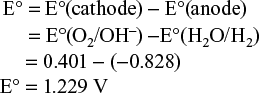
In actual practice, the emf of the cell is 0.8 to 1.0 V. A fuel cell battery or fuel battery comprise of an arrangement of such cells in parallel or series (modules/stack of cells).
Uses of H2−O2 Fuel Cells
- H2−O2 fuel cell is generally used in space craft because of their high efficiency, lightness and product water is a source of fresh water for the astronauts.
- It is also used in submarines or other military vehicles.
- This cell is used as the primary source of electrical energy on the Apollo moon flights.
Approximately 200 kg of fuel is sufficient for 11 days in space.
Types of H2−O2 Fuel Cell
On the basis of the type of electrolyte used in fuel cell, they are of five types:

Fuel Cells and their Characteristic Features

(ii) Methanol-oxygen fuel cell: The Half cell reactions for such cells are:

Advantages of Fuel Cell
- The energy conversion (chemical into electrical) is very high by fuel cells (75−82.8%).
- H2−O2 fuel cell produces H2O, which is used as drinking purpose by astronauts.
- Noise and thermal pollution are low.
- Such type of cells never becomes dead, because of continuous supply of fuel.
- Modular and other parts of fuel cells are exchangeable.
- Fuels cells having low maintenance cost.
- Fuels cells saves fossil fuels.
- The regenerative H2–O2 fuel cell is an energy storage system for space application, submarines and other military vehicles.
Limitations of Fuel Cells
- High initial cost.
- Large weight and volume of gas-fuel storage system.
- High cost of pure hydrogen.
- Liquifaction of hydrogen requires 30% of the stored energy.
- Life-times of such type of cells are not accurately known.
- Most alkaline cells suffer from CO2 degradation and hence CO2 should be removed from the fuels and the air.
5.16 REVIEW QUESTIONS
5.16.1 Fill in the Blanks
- The electrolyte whose solution conducts electricity to a small extent is called a _______
[Ans.: Weak electrolyte]
- The electrolytic conductance _______ with temperature.
[Ans.: increases]
- The unit of specific conductance is _______
[Ans.: ohm−1 cm−1]
- Specific conductance is the conductance of _______ of the solution
[Ans.: 1 cm3]
- The equivalent conductance _______ with dilution.
[Ans.: Increase]
- The Λ°For a weak electrolyte is calculated by using _______ law.
[Ans.: Kohlrausch]
- An electrochemical cell converts _______ energy into _______ energy.
[Ans.: Chemical, electrical]
- The electrode used in the fuel cell is _______.
[Ans.: Concentrated KOH solution]
- The effect of concentration on the electrode potential is studied by _______ equation.
[Ans.: Nernst]
- Arrangement of electrodes in order of reducing potential is known as _______.
[Ans.: Electrochemical series]
- Calmol electrode having _______ solution an electrolyte
[Ans.: saturated KCl]
- A device which convert the energy of fuel direct into electrical is called as _______ cell.
[Ans.: fuel]
- The substance which conducts electricity without any decomposition is called as _______ conductor.
[Ans.: electronic]
- A unit of molar conductivity is _______.
[Ans.: ohm−1 cm2 mol−1]
- Degree of dissociation (α) =

[Ans.: Λ0]
- The tendency of electrode to loss or gain electrode is called as _______.
[Ans.: Electrode potential]
- Calomel electrode act as _______ electrode.
[Ans.: reference]
- Electrode potential of saturated calomel electrode is _______
[Ans.: 0.2422 V]
- When two like electrodes at different concentrations are dipped in some solution of the electrolyte is called as _______ concentration cell.
[Ans.: Electrode]
- _______ cells are not reversible in nature.
[Ans.: Primary]
- Lithium ion cell is an example of _______ cell.
[Ans.: Secondary]
- In Lead-acid cell _______ is act as electrolyte.
[Ans.: Dilute H2SO4]
5.16.2 Multiple-choice Questions
- The effect of temperature increases on concentration is as follows:
- Metallic conduction increases, electrolytic conduction decreases
- electrolytic conduction increases, metallic conduction decreases
- Both metallic and electrolytic conduction decreases
- Both metallic and electrolytic conduction increases
[Ans.: b]
- The units of equivalent conductance are:
- Ohm−1
- ohm−1 cm−2
- Ohm−1 cm2
- mho cm2
[Ans.: c]
- The cell constant is


- a × l

[Ans.: a]
- Effect of dilution on conduction is as follows:
- Specific conductance increases, molar conductance decreases
- Specific conductance decreases, molar conductance increases
- Both increases with dilution
- Both decreases with dilution
[Ans.: b]
- The units of the cell constant is
- cm−1
- cm2
- cm3
- cm−2
[Ans.: a]
- The potential of a single electrode is a half cell is called as
- Reduction potential
- Half-wave potential
- Single electrode potential
- Cell potential
[Ans.: a]
- Which of the following constitutes Daniel Cell?
- Zn − Ag cell
- Cu − Ag cell
- Zn − Cu cell
- none of these
[Ans.: c]
- EMF of a cell in terms of reduction potential of its left and right electrode
- E = Eleft + Eright
- E = Eleft − Eright
- E = Eright − Eleft
- None of these
[Ans.: c]
- Which of the following is a secondary cell
- Dry cell
- Mercury cell
- Ni – Cd cell
- H2 – O2 cell
[Ans.: c]
- An electrochemical cell stops working after some time because
- One of the electrodes is eaten away
- electrode potentials of both electrodes becomes equal in magnitude
- electrode potentials of both the electrodes go on decreasing
- electrode potentials of both the electrodes go on increasing
[Ans.: b]
- The standard EMF (E°) for the cell reaction
Zn + Cu2+ → Zn2+ + Cu is 1.1 volt at 25 °C. The EMF(E) of the cell reaction when 0.1M Cu2+ and 0.1 M Zn2+ solutions are used, at 25 °C is
- 1.10 V
- 0.10 V
- −1.10 V
- −0.110 V
[Ans.: a]
- In an electrochemical cell
- Potential energy decreases
- Kinetic energy decreases
- Potential energy changes into electrical energy
- Chemical energy changes into electrical energy
[Ans.: d]
- As lead storage battery is charged
- lead dioxide dissolves
- sulphuric acid is regenerated
- lead electrode becomes coated with lead sulphate
- the concentration of sulphuric acid decreases
[Ans.: b]
- In an electrochemical series electrodes are arranged in the
- Increasing order (downwards) of standard reduction potential
- Decreasing order of standard reduction potential
- Increasing order of standard oxidation potential
- Increasing order of equivalent weight
[Ans.: a]
- Electrode potential of standard calomel electrode is
- 0.2422 V
- 0.2400 V
- 0.2810 V
- 0.3335 V
[Ans.: a]
- Silver – Silver chloride electrode is a type of
- Redox electrode
- Metal – Metal Ion electrodes
- Metal – Amalgam electrode
- Gas – ion electrode
[Ans.: b]
- Calomel electrode consist of calomel with a solution of
- Saturated NaCl
- Saturated Ca (OH)2
- Saturated KCl
- Saturated AgCl
[Ans.: c]
- Which electrode is used for pH measurement
- Silver electrode
- Redox electrode
- Glass electrode
- Calomel electrode
[Ans.: c]
- Lechanche cell is an example of
- Primary cell
- Secondary cell
- Tertiary cell
- Fuel cell
[Ans.: a]
- A fuel cell converts
- Chemical energy into electrical energy
- Chemical energy into potential energy
- Chemical energy into heat
- Chemical energy into pressure
[Ans.: a]
- Which is produced during H2−O2 fuel cell
- CH3OH
- H2O
- H2O2
- H3O+
[Ans.: b]
- The cathode of Ni – Cd cell is made up from
- NiOH
- Ni (OH)2
- NiO2
- NiO (OH)
[Ans.: d]
- During Charging of lead – acid cell, concentration of H2SO4
- Increases
- Decreases
- Remains unchanged
- First increases then decreases
[Ans.: a]
- In potentiometric titration, graph is plotted between variations of
- Electrode potential with temperature of titrant
- Electrode potential with pressure of titrant
- Electrode potential with volume of titrant
- Electrode potential with concentration of titrant
[Ans.: c]
- At equilibrium, EMF of the cell is
- 0 V
- 100 V
- Less than 0 V
- More than 0 V
[Ans.: a]
- In glass electrode, the glass membrane undergoes exchange of Na+ ion with
- Ca2+
- Mg2+
- H+

[Ans.: c]
- Quinhydrone – electrode consist of hydroquinone (QH2) and quinone (Q) in the ratio of
- 1: 2
- 1:1
- 2:1
- 1:15
[Ans.: b]
- Conductance of an electrode depends upon
- Number of free ions present in solution
- Number of free ions present in solvent
- Concentration of the solution
- Temperature of the solution
[Ans.: a]
- Four metals A, B, C and D are having their reduction potentials as −3.05, −1.66, −0.40 and −0.80 V respectively. Which one of these will be most reducing agent.
- A
- B
- C
- D
[Ans.: a]
- Equivalent conductance of NaCl, HCl and C2H5COONa at infinite dilution are 126.45, 426.16 and 91 ohm−1 cm2 respectively. The equivalent conductance of C2H5COOH at infinite dilution is
- 201.28 ohm−1 cm2
- 390.71 ohm−1 cm2
- 698.28 ohm−1 cm2
- 540.48 ohm−1 cm2
[Ans.: b]
- Saturated Solution of KNO3 is used to make salt bridge because
- Velocity of K+ is greater than that of

- Velocity of is greater than that of K+
- Velocities of both K+ and are nearly the same
- KNO3 is highly soluble in water
[Ans.: c]
- Velocity of K+ is greater than that of
- The specific conductance of
 solution of KCl at 25 °C is 0.002765 ohm−1. If the resistance of the cell is 400 ohms, then what is the value of cell constant
- 2
- 1.106
- 3
- 3.2
[Ans.: b]
- The EMF of the cell Ni | Ni2+ (1.0M) | Au3+(1.0M) | Au
Given that

- 1.25 V
- −1.25 V
- 1.75 V
- 2.00 V
[Ans.: c]
- The conductivity of a saturated solution of BaSO4 is 3.06 × 10⁻⁶ ohm−1 cm2 and its equivalent conductance is 1.53 ohm−1 cm2 equiv−1. The Ksp for BaSO4 will be
- 4 × 10⁻¹²
- 2.5 × 10⁻⁹
- 2.5 × 10⁻¹³
- 4 × 10⁻⁶
[Ans.: d]
- Which of the following does not conduct electricity
- Molten NaCl
- Aqueous NaCl
- Solid NaCl
- Aqueous NH4Cl
[Ans.: c]
5.16.3 Short Answer Questions
- How can you test whether the given electrolyte is a strong electrolyte or a weak electrolyte?
Ans.: If the aqueous solution of the electrolyte conducts electricity to a large extent, it is a strong electrolyte and if to a small extent, it is a weak electrolyte.
- Define specific conductivity and mention its units.
Ans.: The specific conductance of a solution is defined as the conductance of 1 cm3 of the solution of the electrolyte. Its unit is ohm−1 cm−1 (or Ω−1 cm−1) (or S cm−1)
- What is the effect of temperature on the electrical conduction of (i) metallic conductor (ii) electrolytic conductor?
Ans.: With increase of temperature, the electrical conduction of metals decreases whereas that of electrolyte increases.
- Define molar conductance and gives its units.
Ans.: It is defined as the conductance of all the ions produced by dissolving 1 mole of the electrolyte in V cm3 of the solution.
Its units is ohm−1 cm2 mol−1 (or S cm2 mol−1)
- Why do electrochemical cells stop working after some time?
Ans.: Electrochemical cells produce electrical energy at the cost of chemical energy as spontaneous redox reaction takes place in them. When the redox reaction is completed, the cell stops working.
- Give the relationship between molar conductivity and specific conductivity.
Ans.:

Λm = Molar conductivity
K = Specific conductivity
C = Molar concentration
- What is the relationship between specific conductance and equivalent conductance.

- Give the relationship between equivalent and molar conductance.
Ans.:
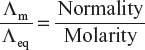
- What is cell constant. Give its units.
Ans.: it is the ratio of the distance between the parallel plates of the cell and the area of electrolyte.

- How is cell constant calculated from conductance values.

- Why voltmeter cannot be used for the precise measurement of EMF of the galvanic cell.
Ans.: Because a part of the cell current is drawn by the voltmeter itself, thereby giving lower value of EMF than the actual one.
- What flows in the internal circuit of galvanic cells?
Ans.: Ions flow in the internal circuits of galvanic cells.
- What is the EMF of the cell when the cell reaction attains equilibrium?
Ans.: At equilibrium, EMF of the cell is zero.
- Can we use a copper vessel to store 1 M AgNO3 solution, given that E °Cu2+/Cu = +0.34 V, E°Ag+/Ag = +0.80 V
Ans.: As the reduction potential of Ag+/ Ag electrode is higher than that of Cu2+/ Cu electrode. So Cu metal is incapable of displacing silver from silver nitrate solution. Thus, we can use a copper vessel to store 1 M AgNO3 solution.
- Why electrode potential of zinc is assigned a negative value; whereas that of copper a positive value.
Ans.: Because Zn electrode is anodic w.r.t. S.H.E and Cu electrode is cathodic w.r.t. S.H.E.
- What is the relationship between the standard EMF of the cell and the equilibrium constant of the cell reaction at 298K?
Ans.:

- What is the electrolyte used in a dry cell.
Ans.: A paste of NH4Cl, MnO2 and C is used in dry cell.
- Why the blue colour of the solution gradually fades when CuSO4 solution is electrolyzed using platinum electrodes.
Ans.: The blue color is due to the presence of Cu2+ ions. During electrolysis these ions are converted into metallic copper hence the blue color fades.
- Define Kohlrausch’s law?
Ans.: At infinite dilution, equivalent conductance of an electrolyte is equal to the sum of ionic conductances of cations and anions at infinite dilution.
- Why D.C current is not used while determining the resistance of an electrolyte?
or
Why only A.C is used and not D.C source in conductometric estimation?
Ans.: If conductometric estimation is carried out by using D.C then the products of electrolysis collect at the electrodes and set up a back emf, Which apparently increases the resistance of the electrolyte. So, such estimations are carried out by using AC and detecting the flow of current.
- What is the basic reason that a lead storage battery can be recharged?
Ans.: PbSO4 is deposited on the electrodes. So, the electrode reactions can be reversed.
- Out of zinc and tin which are protects iron better even after cracks and why?
Ans.: Zinc protects better because oxidation potential of zinc is greater but that of tin is less than that of iron.
- Why does the equivalent conductivity of a weak electrolyte increase with dilution?
Ans.: Because degree of dissociation of weak electrolyte increases with dilution. As a consequence, the total number of ions present per gram equivalent also increases. Hence, equivalent conductivity of weak electrolyte increases with dilution.
- Why equivalent conductivity at infinite dilution for a weak electrolytes solution cannot be determined experimentally.
Ans.: Equivalent conductivity for a weak electrolyte increases steadily with dilution, and the curve between Λeq and
 is not a straight line. The curve does not meet the equivalent conductivity axis. So, the value of Λ∞ cannot be obtained by extrapolation. Hence Λ∞ for a weak electrolyte is determined indirectly by using kohlrausch’s law.
 - Why, with dilution, equivalent conductance increases but specific conductance decreases.
Ans.: With increase in dilution, two things happen, namely degree of dissociation increases, but the total volume increases. The number of ions per cm3 decreases, because the effect of increased volume in decreasing the number of ions per cm3 outweighs the minor increase in conductance with increase of dilution. On the other hand, equivalent conductance increases, because the total number of ions per gram equivalent increases with dilution, due to increased degree of ionization.
- Why a dry cell becomes dead after a long time even if it has not been used?
Ans.: This is because the acidic NH4Cl corrodes the zinc container even if it has not been used.
- Solution of two electrolytes A and B each having a concentration of 0.2 M have conductivities 2 × 10⁻² and 4 × 10⁻⁴ S cm−1 respectively. Which will after greater resistance to the flow of current and why?
Ans.:

Conductivity is reciprocal to resistance. Hence, B will offer greater resistance.
- What is the role of ZnCl2 in dry cell?
Ans.: ZnCl2 combine with NH3 produces to form the complex salt [Zn(NH3)2Cl2] as otherwise the pressure developed due to NH3 would crack the seal of the cell.
- Which types of cells are rechargeable?
Ans.: Those cells are rechargeable in which the products formed during discharge are deposited on the electrodes and these can be decomposed to give the original substances when electrical energy is supplies.
- The standard reduction potential values of three metallic cations X, Y, Z are 0.52, –3.03, –1.18 V respectively. What will be the order of reducing power of the corresponding metals?
Ans.: The standard oxidation potential (equal and opposite in sign of standard reduction potential) of the metals X, Y, Z will be –0.52, 3.03, 1.18 V respectively. Higher the oxidation potential, more easily metal is oxidized and here greater is the reducing power. Hence, the reducing power will be in the order Y > Z > X.
- Why a cell stop working after some time
Ans.: With time, concentration of the electrolytic solutions change. Hence, their electrode potentials change. When the electrode potentials of two half cells become equal, the cell stops working.
- Write any two advantage of H2 – O2 fuel cell over ordinary cell.
Ans.: (i) They do not cause pollution.
(ii) They have high efficiency of 60 – 70%.
- Write the Nearst’s equation for the electrode reaction:

Ans.:

- Define standard hydrogen electrode.
Ans.: Standard hydrogen electrode (SHE) or Normal hydrogen electrode (NHE) is a reference electrode which is obtained by dipping platinum foil in 1M HCl solution through which hydrogen gas is passed at 298 K under 1 atm pressure. Its electrode potential is zero.
- Glass electrode is preferred to quinhydrone electrode in measuring pH of a solution, Give reason.
Ans.: Glass electrode is simple, not easily oxidized and attain equilibrium rapidly. It can safely be used upto pH of 10. On the other hand, quinhydrone electrode can be used upto pH of 8 only. It cannot be used in solutions containing redox system. Hence glass electrode is preferred over quinhydrone electrode in pH measurement of a solution.
- Alkaline dry cells are considered better than Lechanche cell why?
Ans.: Alkaline dry cell lasts longer, because zinc electrode does not corrode easily.
- What is the purpose of MnO2 in dry cell?
Ans.: It acts as an oxidizing agent in dry cell.
- Write the formula for determining the degree of dissociation of weak electrolyte.
Ans.:

- What is the emf of H2 – O2 fuel cell?
Ans.: E° = 1.229 V
- Define fuel cell.
Ans.: Fuel cell is a device which converting energy of a fuel directly into electrical energy.
- What is Lead - acid accumulator?
Ans.: A secondary cell consisting as lead electrodes, the positive one covered with PbO2, dipping into H2SO4 solution. Its emf is about 2V.
- Write major applications of lithium ion cells.
Ans.: Lithium ion cell used in cell phones, laptops, electrical equipment’s etc.
5.16.4 Solved Numerical Problems
- If specific conductivity of
 KCl solution at 298 K is 0.002765 ohm−1 cm−1 and resistance of a cell containing this solution is 100 ohm. Calculate cell constant.
Solution As we know that

Specific conductivity, K = 0.002765 ohm−1 cm−1
Conductance,


- Specific conductivity of a 0.12 N solution of an electrolyte is 0.024 ohm−1 cm−1. Determine its equivalent conductivity.
Solution Equivalent conductivity (Λeq)

Specific conductivity (K) = 0.024 ohm−1 cm−1

- The resistance of a 0.1 N solution of an electrolyte in a conductivity cell was found to be 245 ohms, calculate the equivalent conductivity of the solution if the electrode in the cell were 2 cm apart and each has an area of 3.5 cm2.
Solution

- If the equivalent conductivities at infinite dilution of NaCl, HCl and CH3COONa are 126.4, 426.1 and 91.0 ohm−1 cm2 equiv−1 respectively, what will be the equivalent conductivity at infinite dilution for acetic acid.
Solution According to Kohlrausch’s law

Given that
 (i)
(i) (ii)
(ii) (iii)
(iii)
Adding equations, (ii) and (iii) and subtracting (i), we get λ0(H+) + λ0(Cl−) + λ0(CH3COO−) + λ0(Na+) − λ0(Na+) − λ0(Cl−) = 426.1 + 91.0 – 126.4

- From the following equivalent conductivities at infinite dilution,

Calculate Λ0 for NH4OH
Solution
 (i)
(i) (ii)
(ii) (iii)
(iii) (iv)
(iv)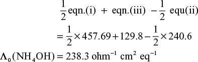
- The equivalent conductivity at infinite dilution of KCl, HCl and CH3COO K are 130.1, 379.4 and 95.6 ohm−1 cm2 eq−1 respectively. Calculate equivalent conductivity at infinite dilution for CH3COOH. If equivalent conductivity of a given acetic acid solution is 48.5 ohm−1 cm2 eq−1 at 25 °C. Calculate the degree of dissociation of CH3COOH at this temperature.
Solution

 (i)
(i) (ii)
(ii) (iii)
(iii)(ii) + (iii) − (i)

- At 291 K the equivalent conductivities at infinite dilution of NH4Cl, NaOH and NaCl are 129.8, 217.4 and 108.9 ohm−1 cm2 respectively. If the equivalent conductivity of a 0.01N solution of NH4OH is 9.33 ohm−1 cm2, what is the percentage dissociation of NH4OH at this dilution? Also calculate the dissociation constant of NH4OH.
Solution
Here, we are given:

By Kohlrausch’s law

Given that, Λ0 for NH4OH = 9.33 ohm−1cm2

Calculation of dissociation constant

So, dissociation constant, K = 1.599 × 10⁻⁵
- The conductivity of a saturated solution of AgCl at 288 K is found to be 1.382 × 10⁻⁶ ohm−1 cm−1. Find it solubility. Given ionic conductances of Ag+ and Cl− at infinite dilution are 61.9 ohm–1 cm2 eq−1 and 76.3 ohm−1 cm2 eq−1 respectively.
Solution
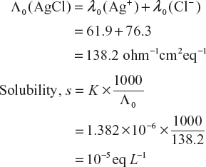
Equivalent weight of CH3 COOH = 143.5g
So, solubility = 143.5 × 10⁻⁵ g L−1
Solubility = 1.435 × 10⁻³ gL−1
- Calculate the standard EMF of a cell which involves the following cell reaction
Zn + 2Ag+→ Zn2+ + 2Ag
Given that E°(Zn2+, Zn) = −0.76 volt
E° (Ag+, Ag) = 0.80 volt
Solution
At L.H.S, Zn → Zn2+ + 2e− (oxidation)
At R.H.S, 2Ag+ + 2e−→ 2Ag (Reduction)

- Can a solution of 1M CuSO4 be stored in a vessel made of nickel metal? Given that
E°(Nl2+, Ni) = −0.25 volt
E°(Cu2+, Cu) = +0.34 volt
Solution In this problem, we want to see.

The cell may be represented as

Thus EMF of the cells comes out to be positive. It means CuSO4 reacts with nickel. Hence, CuSO4 cannot be stored in nickel vessel.
- Calculate the EMF of a Daniel cell at 25 °C, when the concentration of ZnSO4 and CuSO4 are 0.001M and 0.1M respectively. The standard potential of the cell is 1.2 volts.
Solution The cell may be represented as

- Calculate the equilibrium constant for the reaction

Solution
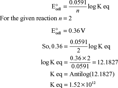
- Calculate the emf of a concentration cell at 25 °C consisting of two Zn electrodes immersed in solutions of Zn2+ ions of 0.1 M and 0.01 M respectively.
Solution EMF of concentration cell at 25 °C is given by

Now for Zn2+/Zn, n = 2

- Find the valency of mercurous ions with the help of following cell:

When the emf measured at 18°C is 0.029 volt.

By solving, n = 2.
- While determining the pH of a solution, the quinhydrone electrode, H+, Q, QH2 was used in conjunction with a saturated calomel electrode as represented below;

The EMF of the cell was found to be 0.2640 volt at 25 °C. Calculate the pH of the solution at this temperature given that

Solution
The EMF of the cell is given by

5.16.5 Descriptive Questions
Q.1 On the basis of electrolytic condition, how are the electrolytes classified.
Q.2 What is an electrochemical series? Discuss its important applications.
Q.3 Explain Kohlrausch’s law of independent migration of ions. Mention one application of kohlrausch’s law.
Q.4 What are concentration cells? Explain with example?
Q.5 What is an ion selective electrode? Explain its principle and working.
Q.6 Explain the following terms.
- Specific conductance
- Molar conductance
- Equivalent conductance.
What will be effect of dilution on them?
Q.7 Discuss briefly conductometric titration.
Q.8 a. In conductrometric titration, more concentrated solution is added from burette, why? What are the advantages of conductrometric titration over ordinary volumetric methods?
b. Draw weak acid – strong base conductometric titration curve and explain it.
Q.9 What is standard electrode potential? Give its importance.
Q.10 a. Why do electrochemical cells stops working after some time?
b. Why does blue color of copper sulphate solution fade when it is electrolyzed using platinum electrodes?
Q.11 What are redox electrodes? Indicate the electrode reaction and electrode potential with suitable example.
Q.12 What is electrochemical series, Give its applications with suitable examples.
Q.13 Describe the following electrodes giving the diagram, electrode notation and electrode reaction
- Standard hydrogen electrode
- Calomel electrode.
Q.14 Write short note on fuel cell, how it is different from commercial cell? Mention the advantages of fuel cells.
Q.15 Write briefly about
- Primary cells
- Secondary cells.
Q.16 Explain the working principle of methanol - oxygen fuel cell.
Q.17 Explain the working principle of Ag - AgCl electrode.
Q.18 Describe the construction of lead-acid battery with the reaction occurring during discharge.
Q.19 How does fuel cell differ from battery?
Q.20 What are reference electrodes? Explain the working of quinhydrone electrode.
Q.21 Explain the composition, applications and advantages of the following cells
- Ni-Cd Cell
- Lithium ion cell
- Dry cell
Q.22 How are specific conductance and equivalent conductance related to concentration of an electrolyte?
Q.23 Explain the measurement of pH of solution using glass electrode. Mention the advantages of this electrode.
Q.24 What is an ion-selective electrode? Explain its working.
Q.25 Explain the construction and functioning of a Daniel cell.
Q.26 Explain the EMF method for determination pH of a solution.
Q.27 What is emf? How is it measured potentiometrically?
Q.28 Derive Nernst equation for the calculation of cell emf.
Q.29 Differentiate primary, secondary and fuel cells with examples.
Q.30 How do you differentiate between EMF series from galvanic series?
5.16.6 Problems for Practice
- The resistance of 0.01 N NaCl solution at 25 °C is 200 ohms. Cells constant of the conductivity cell is unity. Calculate the equivalent conductance of the solution.
[Ans.: 500 ohms−1 cm2]
- Molar conductivity of a 1.5 M solution of an electrolyte is found to be 138.9 S cm2, what would be the specific conductance of this solution.
[Ans.: 0.208 S cm−1]
- The measured resistance of a conductance cell containing 7.5 × 10⁻³ M solution of KCl at 25 °C was 1005 ohms. Calculated (a) specific conductance and (b) molar conductance of this solution. Given that cell constant = 1.25 cm−1
[Ans.: (a) = 0.001244 S cm−1
(b) = 165.87 S cm2 mol−1]
- The resistance of a decinormal solution of a salt occupying a volume between two platinum electrodes 1.8 cm apart and 5.4 cm2 in area was found to be 32 ohms. Calculate equivalent conductance of this solution
[Ans.: 104.1 ohm−1 cm2 eq−1]
- The resistance of 0.2N solution of an electrolyte was found to be 250 ohms at 25 °C. Calculate the equivalent conductivity if the cell constant is 0.75 cm−1
[Ans.: 15 ohm−1 cm2 eq−1]
- Calculate the equivalent conductance at infinite dilution for CH3COOH, given that

[Ans.: 333 ohm−1 cm2 eq−1]
- The equivalent conductance of NaOH, NaCl and BaCl2 at infinity dilution are 2.481 × 10⁻², 1.265 × 10⁻² and 2.800 ×10⁻² ohm−1 m2 eq−1 respectively. Calculate Λ0 for Ba (OH)2.
[Ans.: 5.232 × 10⁻² ohm−1 m2 eq−1]
- If the equivalent conductivities at infinity dilution at 293 K for HCl, CH3COO Na and NaCl are 383.5, 78.4 and 102.0 ohm−1 cm2 respectively. Calculate equivalent conductivity at infinity dilution. The equivalent conductivity of CH3COOH at other dilution is 100.0 ohm−1 cm2 at 293 K, Calculate degree of ionization of acetic acid at this dilution.
[Ans.: Λ0 = 359.9 ohm−1cm2; α = 0.278]
- The specific conductivities of a saturated solution of AgCl is 2.30 × 10⁻⁶ ohm−1 cm−1 at 25 °C. Calculate the solubility of AgCl at 25 °C, Given that
 and λ0(Cl−) are 61.9 and 76.3 ohm−1 cm2 eq−1 respectively.
[Ans.: 2.388 × 10⁻³ gL−1]
- Calculate the percentage dissociation of AgNO3 at 18 °C, given that ionic conductivity of Ag+ and
 ions are 56.7 and 60.5 ohm−1 cm2 eq−1. The specific conductance of a decinormal solution of Ag NO3 at 18 °C is 0.0085 ohm−1 cm−1
[Ans.: 72.52%]
- The equivalent conductivity of 0.025 N HCOOH acid is 46.1 S cm2 eq−1. Calculation its degree of dissociation and dissociation constant. Give that

[Ans.: degree of dissociation, 0.114, Dissociation const, k = 3.67 × 10⁻⁴]
- For the cell show below:

Calculate standard cell potential if standard state reduction electrode potential for Cu2+/Cu and Zn2+/Zn is +0.34 V and – 0.76 V respectively.
[Ans.: 1.10 V]
- Can we use a copper vessel to store 1 M Ag NO3 solution? Given that

[Ans.: No, we can’t use copper vessel to store Ag NO3]
- A galvanic cell consist of a metallic zinc plate immensed in 0.1 M Zn(NO3)2 solution and metallic plate of lead in 0.02 M Pb(NO3)2 solution. Calculate the emf of the cell. Given that standard emf of the cell is 0.63 volts. Also represents the cell reaction.
[Ans.: EMF = 0.6094 volts, cell reaction Zn | Zn2+ || Pb2+| Pb]
- Calculate the EMF of the following cell at 298 K Cd(s) | cd2+ (0.04M) || Ni2+(2.0M) | Ni (s) given that standard EMF of the cell is 0.15 volt.
[Ans.: Ecell = 0.20 volt]
- Calculate the EMF of the following cell
Cr | Cr3+ (0.1M) || Fe2+(0.01M) | Fe
Given that standard EMF of the cell is 0.30 volts
[Ans.: Ecell = 0.2606 volts]
- Calculate the equilibrium constant for the reaction

Given that E° Sn2+/Sn = −0.14 V
E° Pb2+/Pb = −0.13V
[Ans.: Keq = 0.46]
- Calculate the standard emf of the H2–O2 fuel cell, given E° values as −0.40 V and 0.83 V for hydrogen and oxygen half-cell respectively.
[Ans.: 1.23 V]
- Calculate the EMF of the electrode-concentration cell
Pt; H2(p1), HCl, H2(p2); Pt at 25 °C
If p1 = 600 torr and p2 = 400 torr,
[Ans.: Ecell = 5.19 × 10⁻³ V]
- The EMF of the following cell at 25 °C is 0.445 volt. The cell reaction is represented as

Calculate the pH of the unknown solution, give that reduction potential of saturated calomel electrode is 0.2422 volt.
[Ans.: pH = 3.38]