
20
SOLID STATE AND X-RAY DIFFRACTION
20.1 INTRODUCTION
X-ray diffraction on inorganic and organic solids is an increasingly important technique for characterisation, the interpretation of the physical and chemical properties of materials in terms of their ideal or defective atomic structure and the transfer of the acquired crystal chemical knowledge to the engineering of solid-state compounds with novel technological properties in qualitative and quantitative analysis.
Determination of crystal structure was started by Max von Laue and was followed by William Henry Bragg with his son, Lawrence. In 1915, Henry Bragg and Lawrence Bragg were awarded the Nobel Prize for their work; Lawrence remains the youngest winner ever.
Since the discovery of Bragg-type X-ray diffraction from periodic crystal lattices, this technique has become the most essential tool in crystallography in different fields, ranging from the identification of crystalline compounds to get a complete crystal structure.
20.1.1 Crystal Structure
Crystalline solid is a solid in which the constituent structural units are arranged in a definite geometrical configuration. A crystal is a three-dimensional natural grating in which the atoms or molecules are arranged in a definite geometrical shape with flat faces and sharp edges.
The identical units present in a crystal are called unit cell and contain the same number of molecules arranged in exactly the same manner. The shape of the unit cell is explained by three axes (a, b, c) and three angles (α, β, γ). The dimensions of the unit cells of most crystals are roughly of the same order of magnitude as the wavelength of the X-ray.
20.2 CRYSTAL SYSTEMS
Crystal systems can probably be imagined unit cells of many different shapes. However, one of the requirements of a unit cell is that it can be stacked to fill a three-dimensional space; seven unit cell shapes meet this requirement and are known as the seven crystal systems. Crystals can be classified into these seven categories. A list of the these systems in the order of increasing symmetry is shown in Table 20.1.
Table 20.1 Seven crystal systems and their lattice parameters

20.2.1 Laws of Crystallography
There are three laws of crystallography as follows:
Law of Constancy of Interfacial Angles
Under the same physical condition, the substance of the various crystals possess a constant angle between the corresponding phases.
Law of Constancy of Symmetry
In the substance, all crystals are the same and have the same symmetry.
Elements of Symmetry or Symmetrical Elements
There are three types of symmetry.
Plane of Symmetry
It is possible to divide the crystal into two equal parts, one being the mirror image of the other by an imaginary plane. The crystal is said to have a plane of symmetry.
For example, a cubic crystal has two types of symmetry as follows:
- Three rectangular planes of symmetry
- (ii) Six diagonal planes of symmetry
Axis of Symmetry
The axis of symmetry means a line is imagined around which the crystal may be rotated such that it appears unchanged parts in its shape during the complete rotation/revolution. For example, if the crystal having the same appearance n times in one complete rotation, the axis is said to be n fold symmetry. If the values of n can be 2, 3, 4 and 6, the symmetry is known as di, tri, tetra and hexagonal symmetry.
Centre of Symmetry
The centre of symmetry of a crystal is such a point that a line is drawn through it. It intersects the surface of the crystal at equal distances in all directions.
Law of Rational Indices or Rationality of Indices
The indices of any phase of the crystal along the crystallography axis either equal to unit indices or some simple whole number multiplies of it or parallel to it.
For example, OX, OY, OZ, are three crystallographic axis, ABC = a unit crystal, DEF = another crystal, O = centre of crystal.

20.3 CRYSTAL DEFECTS
An ideal crystal of a crystalline solid has all unit cells with the same lattice points in the entire crystal. If the same atoms may not occupy on their position, the crystal shows defects and is known as crystal defect. The crystal defects can be mainly classified into two types. They are stoichiometric defect and non-stoichiometric defects.

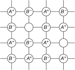
20.3.1 Stoichiometric Defect
In this type of crystal, the number of positive ions and negative ions is equal and the crystal is neutral. These defects are further classified into two types—Schottky defect and Frenkel defect.
Schottky Defect
In this type of defected crystals, positive ions and negative ions may be missed in some places but the number of missing positive and negative ions are equal. This type of defect is also known as point defect.
Example: NaCl(sodium chloride) and CsCl (cesium chloride)
Frenkel Defect
In this type of defect, the hole is created in the crystal lattice when any one of the ion (positive or negative) occupies an interstitial position between lattice points. Frenkel defect is generally observed in ionic crystals in which negative and positive ions differ largely in their ionic radii.

20.3.2 Non-stoichiometric Defect
Non-stoichiometric crystals are those in which positive and negative ions are in a different ratio. These crystals do not obey the law of definite proportions of charges. Hence, there will be excess of either positive or negative ions in a crystal. However, the crystal will be neutral with the equal number of positive and negative charges. Non-stoichiometric defects are further divided into metal excess and metal deficiency defects.
Metal Excess Defects
Metal excess defects may be caused due to loss of negative ions or extra positive ions.
Loss of Negative Ions
If the positive ions are in excess due to missing of negative ions from the lattice, this will be compensated by the presence of extra electron with this the electrical charge is balanced.

Extra Positive Ions
Sometimes, metal excess defect appears due to the presence of extra positive ion in interstitial position of a lattice. To maintain electrical neutrality, an electron also occupies the interstitial position.

Crystals with metal excess defects act as semiconductors; due to the presence of free electrons in the interstitial position of crystal. They can easily flow from one place to another and act as n-type semi-conductors.
Metal Deficiency Defect
Metal deficiency defects may be due to missing of positive ion or extra negative ion.
Missing of Positive Ions
Sometimes, a positive ion is missed from its lattice site and the electrical neutrality is maintained by acquiring two charges on the nearby metal ion instead of one charge. It is necessary to exhibit the metal variable valence to show this defect.

Extra Negative Ion
Sometimes, an extra negative ion may occupy the interstitial position and the extra negative charge is balanced by having an extra positive charge on one of the nearest positive ion. Here also, the metal must be capable of showing variable valence.

20.4 X-RAY DIFFRACTION
20.4.1 Introduction
X-radiation is an electromagnetic radiation with a rough wavelength between 0.1Å and 100Å; similar to inter-atomic distance of a crystal. It allows crystal structures to conveniently diffract X-rays.
X-ray diffraction is used to identify phases by comparison with data from known structures, to quantify changes of cell parameters orientation, crystallise size and other structural parameters. It is also used to determine the crystallographic structure—cell parameters, space group and atomic coordinates of known or unknown crystals.
In crystallography, angstroms (Å) are the units, equal to 10-8 cm or 10-10 m. One angstrom is equal to 0.1 nm.
20.4.2 Principle
When crystalline structures exposed to X-Rays diffraction, it results in an influence structure with geometrical variations, which correspond in the electromagnetic spectrum with wave length X-rays having photon energy between 3 and 8 kev.
20.4.3 X-ray Diffraction of Crystals and Bragg’s Equation
In order to decide the chemical composition of various crystal planes or the mode of distribution of various atoms composing the crystal, X-rays could be used. Bragg pointed out that unlike reflection of monochromatic light, the reflection of X-ray can takes place only at certain angles which are determined by the wavelength of X-rays and the distance between the planes in the crystal. He followed the method of passing a beam of X-rays through a crystal and examining the diffraction spectra produced. The reason for this suggestion was that X-rays possess the same wavelength as interatomic distances in a crystal. The inter-planar distance in the crystal and the angle of reflection is known as Bragg’s equation.
When a beam of X-rays is passed through a crystal, the emergent radiation is allowed to fall on a photographic plate which was placed a few centimeters away from a crystal. The photograph obtained consisted of a central spot surrounded by spots from different diffracted beams. These photographic spots were arranged in a pattern which indicates the symmetry of the crystal. X-ray diffraction of crystal shown in Figure 20.1.

Figure 20.1 X-ray Diffraction of crystals
Consider a set of parallel planes of inter-planar placing d having miller indices (h, k, l). Let a beam of X-rays of wavelength λ be directed towards the crystal at an angle θ to the atomic planes. The interaction between X-rays and electrons of the atoms is visualised as a process of reflection of X-rays by atomic planes. Let a parallel beam of X-rays DE and GH incident on the plane-I and plane-II reflected and the reflected beams are EF and HI.
The atomic phases are considered to be transparent; they allow a part of the wavelength of the rays and reflect the other part, the incident angle θ called Bragg angle is equal to the reflected.
There is a plane angle difference between the X-rays reflected from plane-I and adjacent plane-II in the crystal. The reflected from X-rays EF and HI interfere constructively only when these path difference is equal to an integrated multiple of the wavelength (λ), if d is the inter-planar species, the path difference is JH and HK.
Derivation of Bragg’s Equation
ABC = parallel planes of crystal
DE, GH = incident rays
EF, HI = reflected rays
EJ = perpendicular line at E point for DE ray
EK = perpendicular line at E point for EF ray
The horizontal lines represent the parallel planes in the crystal situated at distance d. The crystal may be imagined as a layer containing cells. The reflection of X-rays can take place only at certain angles determined by the wavelengths of X-rays and the distance between the planes in the crystal. He derived an expression known as Bragg’s equation which gives a simple relation between the wave length of X-ray (λ), the inter planar distance in the crystal (d) and the angle of reflectionθ. A beam of X-rays is incident on the crystal at angle θ.
The DE beam is reflected at point E from the upper surface. The GH beam is reflected at point H from the second lower surface. Let us draw the perpendiculars EJ and EK to the incident and reflected beam at the point of incidence respectively. The difference in the path lengths of the waves reflected from the first two planes is given by JH + HK.
From ΔEJH,

From ΔEHK,

When reflected rays are in same phase, 2d sinθ = nλ.
This equation is known as Bragg’s equation, where n is an integer; When n = 1, first order reflection is obtained. When n = 2, 3, second and third order reflection are obtained.
20.4.4 Determination of Crystal Structure with Bragg’s Equation
A beam of X-rays are passed through a crystal X-rays reflected from different layers. Incident and reflected rays are determined with the help of Bragg’s X-ray spectrometer and also to determine angle θ.
Values are substituted in the equation 2d sinθ = nλ and the crystal structure is determined.
20.4.5 X-ray Diffraction Methods
Powder Method
The powder method is the most widely used method for crystals with simple structures. The powder impact consists of many small crystals, which are oriented with possible directions. As a result, X-rays are scattered from all sets of planes.
The scattered X-rays are detected using on X-ray-sensitive film. Substances to be examined are finely powdered and kept in the form of a cylinder inside the glass tube. A narrow beam of X-rays are allowed to fall on the powder. The diffracted X-rays strike a strip of photographic film arranged in the form of a circular.
In this method, no rotation is necessary, since the powder sample already contains micro crystals arranged in all possible orientation. Hence, a large number of crystal lattice planes are available with the correct position for maximum X-rays to be reflected. As a result lighted areas form a lines with different distances from the incident beam. These distances can be converted into the scattering angles to be used in the Bragg’s equation for different planes of the crystals.
Single Crystal X-ray Diffraction
Single crystal X-ray diffraction can provide detailed information about the internal lattice of crystalline substances, including bond length, bond angles, unit cell dimensions; it is a non-destructive analytical technique.
Principle
This is a constructive interference of monochromatic X-rays and a crystalline sample. The cathode ray tube generates X-rays; the formed rays are filtered to produce monochromatic radiation, collimated to concentrate and directed towards the sample to produce constructive interference. When conditions satisfy the Braggs law nλ = 2d sinθ; that is, the wave length of electromagnetic radiation to the diffraction angle and the lattice spacing in a crystalline sample, these diffracted X-rays are then detected, processed and counted. By changing the geometry of the incident rays, the orientation of the centered crystal and the detectors, all possible diffraction directions of the lattice should be obtained.
All diffraction methods are based on generation of X-rays in an X-ray tube. These X-rays are detected at the sample, and the diffracted rays powder and single-crystal diffraction vary in instrumentation.
20.4.6 Instrumentation of X-ray
When X-Rays are passed through the crystal, the light is diffracted and pattern according to the crystal structure. Regarding electron density map, this pattern can be mapped and analysed; it shows the exact arrangement of atoms in the crystals.
To get a good result, the crystal should be of small size less than one millimeter, perfect without cracks and air bubbles. If the crystals are not perfect gives random patterns and other problems also occurs at the time of end image formation.
Different substances crystallise differently.
- Small molecules generally crystallise easily.
- (ii) Protein or nucleic acids are much harder to crystallise.
Mounting Crystals
The X-ray beam can be passed through the sample; by rotating capillary (or) a tube which contain sample crystals are mounted. Crystals required to be positioned within ∼25 micrometers accuracy of the beam.
Exposing X-rays
Once the crystals are properly mounted, they are exposed to X-ray beams. X-ray sources are synchrotron, X-ray generator, etc.
Reflection
When the X-rays pass through the crystals, the beam is reflected in a space behind the crystal; the reflected pattern can be collected by using regular photographic film and then analysed according to the relative intensity of the spots. By using a goniometer, the diffraction pattern at different angles is obtained for 3D pattern, to obtain correct crystal structure.
Electron Density Map
The 3D structure obtained above is the electron density map. With this map, we get the final structure as given in Figure 20.2.

Figure 20.2 Electron density map
20.5 APPLICATION OF X-RAY DIFFRACTION
X-ray powder diffraction is used to detect and analyse unknown crystalline material in geology, environmental science, material science, engineering, biology, etc. Some applications are as follows:
- To characterise crystalline material.
- To identify fine grained material such as clays, mixed layers clays which are difficult to determine optically.
- To determination unit cell dimensions.
- To check sample purity in qualitative analysis.
- In quantitative analysis of polyphase mixtures
- To determine lattice mismatch between film and substrate and to interfering stress and strain.
- To determine dislocation density and quality of the film by rocking curve measurement.
- To measure super lattice in multilayered epitaxial structure.
- To determine the thickness, roughness and density of the film by using glancing inside X-ray reflectivity measurements.
- To make textural measurements, such as the orientation of grains, in a ploy crystalline sample.
- To undertake in charge density studies
- To physically analyse crystalline aggregates such as orientation, texture, crystallite size distribution, and lattice micro strain effects, etc.
20.6 REVIEW QUESTIONS
20.6.1 Fill in the Blanks
- 1. X-ray crystallography is used to detect the_____________.
[Ans. Crystalline structure]
- 2. X-rays having photon energy are __________.
[Ans. 3 to 8 keV]
- 3. The size of crystal in instrumentation of X-rays is ___________.
[Ans. 1mm]
20.6.2 Multiple-choice Questions
- 1. Units used in crystallography is
- Angstrome
- m/s
- Nanometer
- None of these
[Ans. a]
- 2. 1 Å = ___________ nm.
- 0.01 nm
- 1 nm
- 0.1 nm
- All the above
[Ans. c]
- 3. Wave length of X-rays in between
- 0.1 to 100 Å
- 1 to 200 Å
- 0.1 to 0.01 Å
- No range
[Ans. a]
- 4. Bragg equation nλ = ___________
- 2d sinθ
- 3d sinθ
- 4d sinθ
- nd sinθ
[Ans. a]
- 5. The method used to detect simple crystal structures is
- Crystal method
- Solid method
- Liquid method
- Powder method
[Ans. d]
20.6.3 Short Answer Questions
- 1. Give a short note on X-ray crystallography.
Ans.: X-ray radiation of electromagnetic radiation wavelength in between 0.1Å to 100Å is used to detect the structure of crystals.
- 2. Explain the important tools in X-ray diffraction.
Ans.: It is an important tool used to detect the following:
- Structure of the crystals
- Quantity change of cell parameter and orientation
- Size of the crystallite
- Cell parameters, space group, atomic co-ordinates.
- 3. Explain the Bragg’s equation.
Ans.: The inter-planar distance in the crystals and the angle of reflection is known as Bragg’s equation; it is represented by nλ = 2d sinθ.
- 4. Give a note on powder method.
Ans.: The powder method is most widely used particularly for crystals with sample structure.
- 5. Write the source for X-ray diffraction.
Ans.: (a) X-ray beam
(b) Synchrotron
(c) X-ray generator
20.6.4 Descriptive Questions
Q.1 Describe the principle of X-ray diffraction.
Q.2 Give a detailed note on Bragg’s equation for X-ray diffraction.
Q.3 Write a note on powder method and its importance.
Q.4 Give a brief account of single crystal X-ray diffraction.
Q.5 Explain the instrumentation of X-ray diffraction.