Variable frequency operation of induction motors
Abstract
Supplying the induction motor at variable frequency not only gets round most of the problems inherent in the motor, but also, and most importantly, it converts the motor into an outstandingly successful variable speed drive. The steady-state behaviour is dealt with in this chapter, including current-source and voltage-source inverters; constant torque and constant power regions; four-quadrant operation; effects of the inverter on the motor and vice versa; and the effect of the inverter on the utility supply. A grasp of this chapter is advisable before moving to Chapter 8.
Keywords
Induction motor; Variable frequency operation; Inverter; PWM; Voltage source; Current source; Closed-loop; Inverter grade motors
7.1 Introduction
We saw in Chapter 6 the many attributes of the induction motor which have made it the preferred workhorse of industry. These include simple low cost construction, which lends itself to totally enclosed designs suitable for dirty or even hazardous environments; limited routine maintenance with no brushes; only three power connections; and good full load efficiency. We have also seen that when operated from the utility supply there are a number of undesirable characteristics, the most notable being that there is only one speed of operation (or more precisely a narrow load-dependent speed range). In addition, starting equipment is often required to avoid excessive currents of up to six times rated current when starting direct on line; reversal requires two of the power cables to be interchanged; and the instantaneous torque cannot be controlled, so the transient performance is poor.
We will see in this chapter that all the good features of the utility-operated induction motor are retained and all the bad characteristics detailed above can be avoided when the induction motor is supplied from a variable-frequency source, i.e. its supply comes from an inverter.
The first part of this chapter deals with the steady-state behaviour when the operating frequency is solely determined by the inverter, and is independent of what is happening at the motor. We will refer to this set-up as ‘inverter-fed’, and in the early days of converter-driven induction motors this was the norm—the frequency being set by an oscillator that controlled the sequential periodic switching of the devices in the inverter. We will see that by appropriate control of the frequency and voltage we are able to operate over a very wide range of the torque-speed plane, but we will also identify the limits on what can be achieved.
On a steady-state basis, the inverter-fed arrangement proved able to compete with the d.c. drive, but even when incorporated into a closed-loop speed control scheme the transient performance remained inferior.
The reason for the superior inherent transient performance of the d.c. drive is that the torque is directly proportional to the main armature (rotor) current, which can be measured easily, and directly controlled with a high-gain current control loop. In complete contrast, the rotor current in the cage induction motor obviously cannot be measured directly, and any changes have to be induced from the stator side.
We will see in Chapter 8 that the field-oriented technique allows rapid and precise control of the rotor current (and hence torque), which it achieves by sophisticated control of the inverter switching according to what is happening in the motor. This technique (which was only made possible when cheap real-time digital processing became available) results in outstanding dynamic performance, but understanding how it works is relatively challenging, and can be confusing even for engineers with considerable experience of drive systems.
For some readers, understanding these relatively complex control schemes will not be necessary, while for others, getting to grips with and understanding advanced control strategies is critically important. The authors therefore decided that although it will be appropriate to make reference to the remarkable capabilities of field-oriented systems in this chapter, it would be best to defer detailed consideration to Chapter 8.
At this stage it is important to stress that there is no real difference between the traditional inverter-fed drive and the field oriented drives under true steady-state running conditions—a fact that is often not appreciated. It is therefore well worth absorbing the main messages from Section 7.2 (variable-frequency steady-state operation) because it covers most of the fundamental aspects applicable to all induction motor drives.
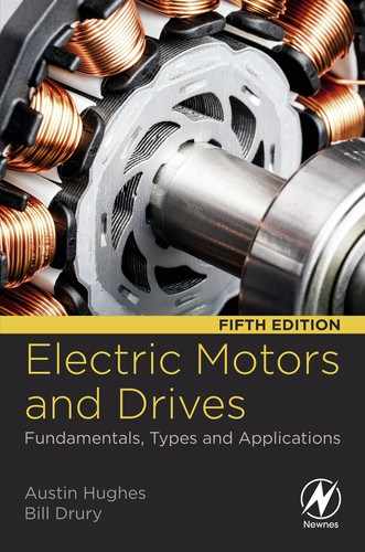
For most of this chapter we will assume that the motor is supplied from an ideal balanced sinusoidal voltage source. Our justification for doing this is that although the pulse-width-modulated voltage waveform supplied by an inverter will not be sinusoidal (see Fig. 7.1), the motor performance depends principally on the fundamental (sinusoidal) component of the applied voltage. This is a somewhat surprising but extremely welcome simplification, because it allows us to make use of our knowledge of how the induction motor behaves with a sinusoidal supply to anticipate how it performs when fed from an inverter.
In Section 7.3, we look at some of the practical aspects of inverter-fed induction motor drives and consider the impressive performance of commercially available drives. Having alluded to the excellent performance offered by advanced control strategies (see Chapter 8), for the sake of balance, we will look at an application where Field Orientation struggles and Direct Torque Control simply doesn't work.
The adoption of the standard induction motor in a variable speed drive is not without potential problems, so in Section 7.4 we look at the more important practical issues which affect the motor, and in Section 7.5 we consider the pros and cons from the point of view of the utility supply. Finally, in Section 7.6, we look briefly at inverter and motor protection.
7.2 Variable frequency operation
It was explained in Chapter 6 that the induction motor can only run efficiently at low slips, i.e. close to the synchronous speed of the rotating field. The best method of speed control must therefore provide for continuous smooth variation of the synchronous speed, which in turn calls for variation of the supply frequency. This is readily achieved using a power electronic inverter (as discussed in Chapter 2) to supply the motor. A complete speed control scheme, which is illustrated with speed feedback, is shown in simplified block diagram form in Fig. 7.2.

The arrangement shown in Fig. 7.2 shows the motor with a speed sensor/incremental encoder attached to the motor shaft. For all but the most demanding dynamic applications, or where full torque at standstill is a requirement, a speed sensor would not normally be required. This is good news because fitting a speed sensor to a standard induction motor involves extra cost and additional cabling.
We should recall that the function of the converter (i.e. rectifier and variable-frequency inverter) is to draw power from the fixed-frequency constant-voltage supply, rectify it and then convert it to variable-frequency, variable-voltage for driving the induction motor. Both the rectifier and the inverter employ switching strategies (see Chapter 2), so the power conversions are accomplished efficiently and the converter can be compact.
7.2.1 Steady-state operation—Importance of achieving full flux
Three simple relationships need to be borne in mind in order to simplify understanding of how the inverter-fed induction motor behaves. Firstly, we established in Chapter 5 that for a given induction motor, the torque developed depends on the magnitude of the rotating flux density wave, and on the slip speed of the rotor, i.e. on the relative velocity of the rotor with respect to the flux wave. Secondly, the strength or amplitude of the flux wave depends directly on the supply voltage to the stator windings, and inversely on the supply frequency. Thirdly, the absolute speed of the flux wave depends directly on the supply frequency.
Recalling that the motor can only operate efficiently when the slip is small, we see that the basic method of speed control rests on the control of the speed of rotation of the flux wave (i.e. the synchronous speed), by control of the supply frequency. If the motor is a 4-pole one, for example, the synchronous speed will be 1500 rev/min when supplied at 50 Hz, 1800 rev/min at 60 Hz, 750 rev/min at 25 Hz, and so on. The no-load speed will therefore be almost exactly proportional to the supply frequency, because the torque at no load is small and the corresponding slip is also very small.
Turning now to what happens on load, we know that when a load is applied the rotor slows down, the slip increases, more current is induced in the rotor, and more torque is produced. When the speed has reduced to the point where the motor torque equals the load torque, the speed becomes steady. We normally want the drop in speed with load to be as small as possible, not only to minimise the drop in speed, but also to maximise efficiency: in short, we want to minimise the slip for a given load.
We saw in Chapter 5 that the slip for a given torque depends on the amplitude of the rotating flux wave: the higher the flux, the smaller the slip needed for a given torque. It follows that having set the desired speed of rotation of the flux wave by controlling the output frequency of the inverter we must also ensure that the magnitude of the flux is adjusted so that it is at its full (rated) value,1 regardless of the speed of rotation. This is achieved, in principle, by making the output voltage from the inverter vary in the appropriate way in relation to the frequency.
Given that the amplitude of the flux wave is proportional to the supply voltage and inversely proportional to the frequency, it follows that if we arrange that the voltage supplied by the inverter varies in direct proportion to the frequency, the flux wave will have a constant amplitude. This simple mode of operation—where the V/f ratio is constant—was for many years the basis of the control strategy applied to most inverter fed induction motors, and it can still be found in some commercial products.
Many inverters are designed for direct connection to the utility supply, without a transformer, and as a result the maximum inverter output voltage is limited to a value similar to that of the supply system. Since the inverter will normally be used to supply a standard induction motor designed, for example for 400 V, 50 Hz operation, it is obvious that when the inverter is set to deliver 50 Hz, the voltage should be 400 V, which is within the inverter's voltage range. But when the frequency was raised to say 100 Hz, the voltage should—ideally—be increased to 800 V in order to obtain full flux. The inverter cannot supply voltages above 400 V, and it follows that in this case full flux can only be maintained up to base speed. Established practice is for the inverter to be capable of maintaining the “V/f ratio”, or rather the flux, constant up to the base speed (frequently 50 Hz or 60 Hz), but to accept that at higher frequencies the voltage will be constant at its maximum value. This means that the flux is maintained constant at speeds up to base speed, but beyond that the flux reduces inversely with frequency. Needless to say the performance above base speed is adversely affected, as we will see.
Users are sometimes alarmed to discover that both voltage and frequency change when a new speed is demanded. Particular concern is expressed when the voltage is seen to reduce when a lower speed is called for. Surely, it is argued, it can't be right to operate say a 400 V induction motor at anything less than 400 V. The fallacy in this view should now be apparent: the figure of 400 V is simply the correct voltage for the motor when run directly from the utility supply, at say 50 Hz. If this full voltage was applied when the frequency was reduced to say 25 Hz, the implication would be that the flux would rise to twice its rated value. This would greatly overload the magnetic circuit of the machine, giving rise to excessive saturation of the iron, an enormous magnetising current, and wholly unacceptable iron and copper losses. To prevent this from happening, and keep the flux at its rated value, it is essential to reduce the voltage in proportion to frequency. In the case above, for example, the correct voltage at 25 Hz would be 200 V.
It is worth stressing here that when considering a motor to be fed from an inverter there is no longer any special significance about the utility network frequency, and the motor can be wound for almost any base frequency. For example a motor wound for 400 V, 100 Hz could, in the above example, operate with constant flux right up to 100 Hz.
7.2.2 Torque-speed characteristics
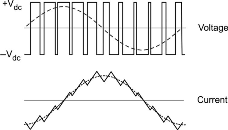
When the voltage at each frequency is adjusted so that the ratio of voltage to frequency (V/f) is kept constant up to base speed, a family of torque speed curves as shown in Fig. 7.3 is obtained. These curves are typical for a standard induction motor of several kW output.
As expected, the no-load speeds are directly proportional to the frequency, and if the frequency is held constant e.g. at 25 Hz in Fig. 7.3, the speed drops only modestly from no-load (point a) to full-load (point b). These are therefore good, useful open-loop characteristics, because the speed is held fairly well from no-load to full-load. If the application calls for the speed to be held precisely, this can clearly be achieved by raising the frequency so that the full-load operating point moves to point (c).
We note also that the pull-out torque and the torque stiffness (i.e. the slope of the torque-speed curve in the normal operating region) is more or less the same at all points below base speed, except at low frequencies where the voltage drop due to the stator resistance becomes very significant as the applied voltage is reduced. A simple V/f control system would therefore suffer from significantly reduced flux and hence less torque at low speeds, as indicated in Fig. 7.3.
The low-frequency performance can be improved by increasing the V/f ratio at low frequencies in order to restore full flux, a technique which is referred to as ‘voltage boost’. In modern drive control schemes which calculate flux from a motor model (see Chapter 8), the voltage is automatically boosted from the linear V/f characteristic that the approximate theory leads us to expect. A typical set of torque-speed curves for a drive with the improved low-speed torque characteristics obtained with voltage boost is shown in Fig. 7.4.

The characteristics in Fig. 7.4 have an obvious appeal because they indicate that the motor is capable of producing practically the same maximum torque at all speeds from zero up to the base (50 Hz) speed. This region of the characteristics is known as the ‘constant torque’ region, which means that for frequencies up to base speed, the maximum possible torque which the motor can deliver is independent of the set speed. Continuous operation at peak torque will not be allowable because the motor will overheat, so an upper limit will be imposed by the controller, as discussed shortly. With this imposed limit, operation below base speed corresponds to the armature-voltage control region of a d.c. drive, as exemplified in Fig. 3.9.
We should note that the availability of high torque at low speeds (especially at zero speed) means that we can avoid all the ‘starting’ problems associated with fixed-frequency operation (see Chapter 6). By starting off with a low frequency which is then gradually raised, the slip speed of the rotor is always small, i.e. the rotor operates in the optimum condition for torque production all the time, thereby avoiding all the disadvantages of high-slip (low torque and high current) that are associated with utility-frequency/Direct-on-Line (DOL) starting. This means that not only can the inverter-fed motor provide rated torque at low speeds, but—perhaps more importantly—it does so without drawing any more current from the utility supply than under full-load conditions, which means that we can safely operate from a weak supply without causing excessive voltage dips. For some essentially fixed-speed applications, the superior starting ability of the inverter-fed system alone may justify its cost.
Beyond the base frequency, the flux (“V/f ratio”) reduces because V remains constant. The amplitude of the flux wave therefore reduces inversely with the frequency. Under constant flux operation, the pull-out torque always occurs at the same absolute value of slip, but in the constant-voltage region the peak torque reduces inversely with the square of the frequency and the torque-speed curve becomes less steep, as shown in Fig. 7.4.
Although the curves in Fig. 7.4 show what torque the motor can produce for each frequency and speed, they give no indication of whether continuous operation is possible at each point, yet this matter is extremely important from the users viewpoint, and is discussed next.
7.2.3 Limitations imposed by the inverter—Constant torque and constant power regions
A primary concern in the inverter is to limit the currents to a safe value as far as the main switching devices and the motor are concerned. The current limit will be typically set to the rated current of the motor, and the inverter control circuits will be arranged so that no matter what the user does the output current cannot exceed this safe (thermal) value, other than for clearly defined overload (e.g. 120% for 60 s) for which the motor and inverter will have been specified and rated. (For some applications involving a large number of starts and stops, the motor and drive must be specially designed for the specific duty.)
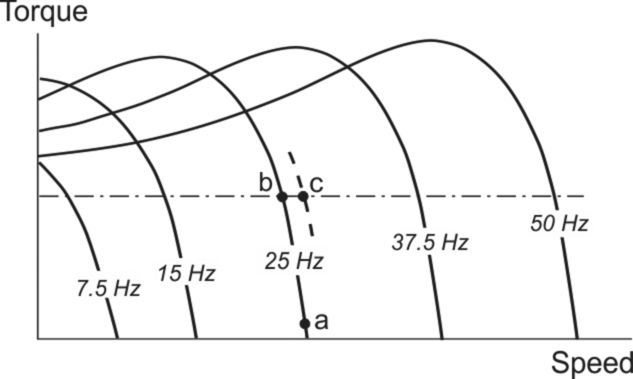
In modern control schemes (see Chapter 8) it is possible to have independent control of the flux and torque producing components of the current, and in this way the current limit imposes an upper limit on the permissible torque. In the region below base speed, this will normally correspond to the rated torque of the motor, which is typically about half the pull-out torque, as indicated by the shaded region in Fig. 7.5.
Above base speed, it is not possible to increase the voltage and so the flux reduces inversely with the frequency. Since the inverter current is thermally limited (as we saw in the constant torque region), the maximum permissible torque also reduces inversely with the speed, as shown in Fig. 7.5. This region is consequently known as the ‘constant power’ region: in this region, the flux is reduced and so the motor has to operate with higher slips than below base speed to develop the full (rated) rotor current and correspondingly reduced torque. There is of course a close parallel with the d.c. drive here, both systems operating with reduced or weak field in the constant power region. Note that if an inverter with a higher current rating were used, the motor would still operate with high slip, meaning high rotor losses and the thermal rating of the motor would become the critical factor, which we will explore next.
At all speeds in the constant power region, the maximum torque available is limited by the inverter current limit, the motor itself having some reserve before it reaches its pull-out torque. However, with constant voltage, the pull-out torque is inversely proportional to the square of the frequency, so the upper bound on torque ultimately becomes limited by the motor itself, rather than the inverter. This is shown by the hatched area in Fig. 7.5: the transition to this ‘high-speed region’ typically occurs at about twice base speed.
7.2.4 Limitations imposed by the motor
The traditional practice in d.c. drives is to use a motor specifically designed for operation from a thyristor converter. The motor will have a laminated frame, will probably come complete with a tacho, and—most important of all—will have been designed for through ventilation and equipped with an auxiliary air blower. Adequate ventilation is guaranteed at all speeds, and continuous operation with full torque (i.e. full current) at even the lowest speed is therefore in order.
By contrast, it is still common for inverter-fed systems to use a standard industrial induction motor. These motors are usually totally enclosed, with an external shaft-mounted fan which blows air over the finned outer case (and an internal stirring fan to circulate air inside the motor to avoid spot heating). They are designed first and foremost for continuous operation from the fixed frequency utility supply, running at base speed.
As we have mentioned earlier, when such a motor is operated at a low frequency (e.g. 7.5 Hz), the speed is much lower than base speed and the efficiency of the cooling fan is greatly reduced. At the lower speed the motor will be able to produce as much torque as at base speed (see Fig. 7.4) but in doing so the losses in both stator and rotor will also be more or less the same as at base speed, so it will overheat if operated for any length of time.
However, induction motors bearing the name ‘inverter grade’ or similar are today readily available. As well as having reinforced insulation systems (see Section 7.4.5), they have been designed to offer a constant torque operating range below rated speed, typically down to 30% of base speed, without the need for an external cooling fan. In addition they may be offered with a separate external cooling fan to allow operation at constant (rated) torque down to standstill.
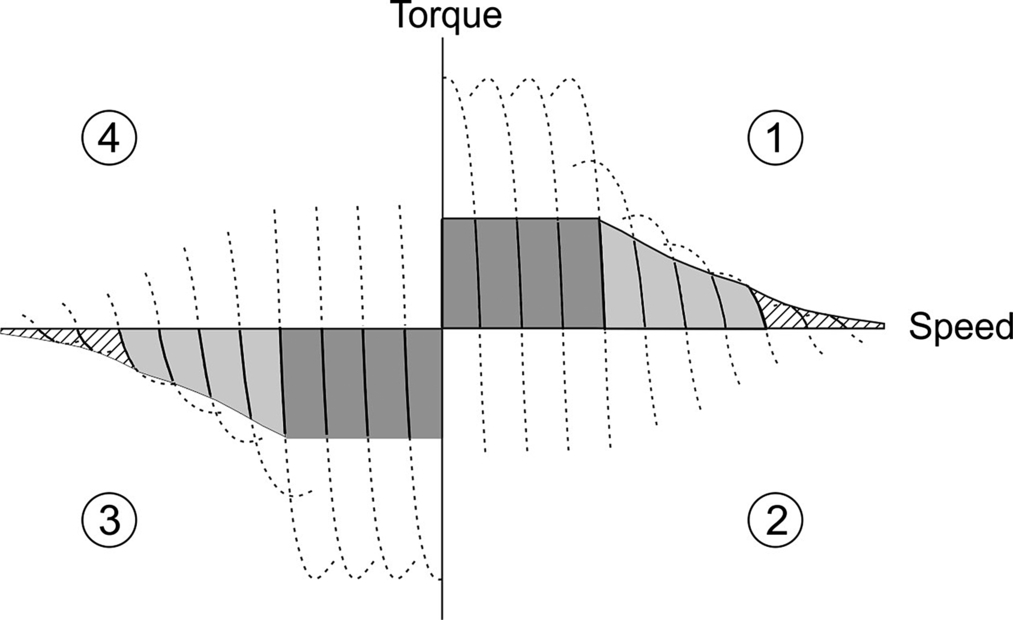
7.2.5 Four quadrant capability
So far in this chapter it is natural that we have concentrated on motoring in quadrant 1 of the torque-speed plane (see Fig. 3.12), because this is how the machine will spend most of its time, but it is important to remind ourselves that the induction motor is equally at home as a generator, a role that it will frequently perform, even with an ordinary load, when a reduction in speed is called for. We should also recall that in this part of the chapter we are studying variable-frequency operation at the fundamental level, so we should bear in mind that in practice details of the control strategy will vary from drive to drive.
We can see how intermittent generation occurs with the aid of the torque-speed curves shown in Fig. 7.6. These have been extended into quadrant 2, i.e. the negative-slip region, where the rotor speed is higher than synchronous, and a braking torque is exerted.

The family of curves indicate that for each set speed (i.e. each frequency) the speed remains reasonably constant because of the relatively steep torque-slip characteristic of the cage motor. If the load is increased beyond rated torque, an internal current limit comes into play to prevent the motor from reaching the unstable region beyond pull-out. Instead, the frequency and speed are reduced, and so the system behaves in a similar way to a d.c. drive.
Sudden changes in the speed reference are buffered so that the frequency is gradually increased or decreased. If the load inertia is low and/or the ramp time sufficiently long, the acceleration will be accomplished without the motor entering the current-limit region. On the other hand if the inertia is large and/or the ramp time was very short, the acceleration will take place as discussed below.
Suppose the motor is operating in the steady state with a constant load torque at point (a), when a new higher speed corresponding to point (d) is demanded. The frequency is increased, causing the motor torque to rise to point (b), where the current has reached the allowable limit. The rate of increase of frequency is then automatically reduced so that the motor accelerates under constant-current conditions to point (c), where the current falls below the limit: the frequency then remains constant and the trajectory follows the curve from (c) to settle finally at point (d).
A typical deceleration trajectory is shown by the path aefg in Fig. 7.6. The torque is negative for much of the time, the motor operating in quadrant 2 and regenerating kinetic energy. Because we have assumed that the motor is supplied from an ideal voltage source, this excess energy will return to the supply automatically. In practice however we should note that many drives do not have the capability to return power to the a.c. supply, and the excess energy therefore has to be dissipated in a resistor inside the converter. (The resistor is usually connected across the d.c. link, and controlled by a chopper. When the level of the d.c. link voltage rises, because of the regenerated energy, the chopper switches the resistor on to absorb the energy. High inertia loads which are subjected to frequent deceleration can therefore pose problems of excessive power dissipation in this ‘dump’ resistor.)
To operate as a motor in quadrant 3 all that is required is for the phase sequence of the supply to be reversed, say from ABC to ACB. Unlike the utility-fed motor, there is no need to swap two of the power leads because the phase sequencing can be changed easily at the low-power logic level in the inverter. With reverse phase sequence, a mirror image set of ‘motoring’ characteristics are available, as shown in Fig. 7.7. The shaded regions are as described for Fig. 7.5, and the dotted lines indicate either short-term overload operation (quadrants 1 and 3) or regeneration during deceleration (quadrants 2 and 4).
Note that unlike the d.c. motor control strategies we examined in Chapter 4, neither the motor current, nor indeed any representation of torque, play a role in the motor control strategy discussed so far (except when the current hits a limit, as discussed above).
We have seen that the inverter-fed induction motor is a very versatile variable speed drive. The control systems presented so far are rather simple, all based in principle on keeping the ratio of stator voltage to fundamental frequency constant, in an attempt to keep the air-gap flux constant and give the motor the potential for providing rated torque at the desired frequency. This form of control has many drawbacks, and in recent years a large number of commercial drive systems employ either Field-Oriented (sometimes referred to as Vector) Control or Direct Torque Control. These are discussed in Chapter 8. Before we move on to that however, there are a number of practical issues associated with inverter-fed induction motors, which are important to understand regardless of the particular type of drive in question.
7.3 Practical aspects of inverter-fed drives
In this section we look at some of the practical aspects of inverter-fed induction motor drives and briefly consider the impressive performance of commercially available drives. By using Field-Oriented or Direct Torque Control (which we will cover in Chapter 8) it is possible to achieve not only steady-state speed control but also dynamic performance superior to that of a thyristor d.c. drive: such performance is dependent on the ability to perform very fast/real-time modelling of the motor and very rapid control of the motor voltage magnitude and phase.
Whilst it comes as no surprise that the inverter-fed induction motor is now the best-selling industrial drive, the adoption of the standard induction motor in a variable speed drive is not without potential problems, so it is important to be aware of their existence and learn something of the methods of mitigation. We will therefore consider some of the more important practical issues which result from operating standard (utility supply) motors from a variable frequency inverter.
7.3.1 PWM voltage source inverter
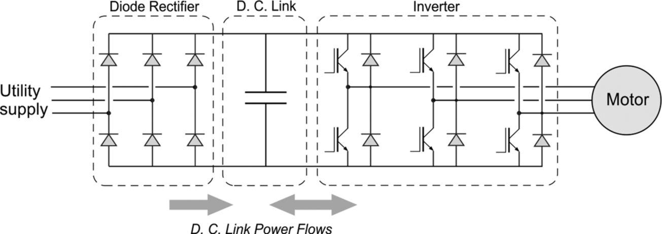
Several alternative drive topologies are applied to induction motors and the most relevant of these have been discussed in Chapter 2. There is also one seldom-used topology that is unique to induction motors, which we discuss briefly in Section 7.3.2. However, by far the most important for most industrial applications has a diode bridge rectifier (which only allows energy flow from the supply to the d.c. link) and a Pulse Width Modulated (PWM) Voltage Source Inverter (VSI), as shown in Fig. 7.8, and this arrangement will now be the focus of our attention.
Most low power inverters use MOSFET switching devices in the inverter bridge, and may switch at ultrasonic frequencies, which naturally results in quiet operation. Medium and larger power inverters use IGBT's which can be switched at high enough frequencies to be ultrasonic for most of the population. It should be remembered however that the higher the switching frequency2 the higher the inverter losses, and hence the lower the efficiency, and so a compromise must be reached.
Inverter-fed induction motor drives are used in ratings up to many megawatts. Standard 50 Hz or 60 Hz motors are often used, though the use of a variable frequency inverter means that motors of almost any rated/base frequency can be employed. We saw earlier in this chapter that operation above base frequency limits performance and so this needs to be carefully considered when specifying a drive system. Commercially available inverters operate with output frequencies typically from 0 Hz up to perhaps several hundred Hz, and in some cases to much higher frequencies. The low frequency limit is generally determined by the form of control, whilst the higher frequency depends on the control and the physical dimensioning of the power electronic circuits (where stray inductance can be a problem if (internal to the inverter) interconnections become too long).
The majority of inverters are three-phase input and three-phase output, but single-phase input versions are available up to about 7.5 kW. Some inverters (usually less than 3 kW) are specifically designed for use with single-phase motors, but these are unusual and will not be considered further. The upper operating frequency is generally limited by the mechanical stresses in the rotor. Very high speed motors for applications such as centrifuges and wood working machines can be designed, with special rotor construction and bearings, for speeds up to 50,000 rev/min, or occasionally even higher.
A fundamental aspect of any converter, which is often overlooked, is instantaneous energy balance. In principle, for any balanced three-phase load, the total load power remains constant from instant to instant, so if it was possible to build an ideal three-phase input, three-phase output converter, there would be no need for the converter to include any energy storage elements. In practice, all converters require some energy storage (in capacitors or inductors), but these are relatively small when the input is three-phase because the energy balance is good. However, as mentioned above, many low power (and some high power, rail traction) converters, are supplied from a single-phase source. In this case, the instantaneous input power is zero at least four times per cycle of the supply (because the voltage and current each go through zero every half-cycle). If the motor is three-phase and draws power at a constant rate from the d.c. link, it is obviously necessary to store sufficient energy in the converter to supply the motor during the brief intervals when the load power is greater than the input power. This explains why the most bulky components in many power inverters are electrolytic3 capacitors in the d.c. link. (Some drive manufacturers are now designing products, for connection to a 3 phase supply, with low values of d.c. capacitance for undemanding applications where the subsequent reduction in control/performance is acceptable).
The output waveform produced by the PWM inverter in an a.c. drive also brings with it challenges for the motor, which we will consider later. When we looked at the converter-fed d.c. motor we saw that the behaviour was governed primarily by the mean d.c. voltage, and that for most purposes we could safely ignore the ripple components. A similar approximation is useful when looking at how the inverter-fed induction motor performs: we assume that although the voltage waveform supplied by the inverter will not be sinusoidal, the motor behaviour depends principally on the fundamental (sinusoidal) component of the applied voltage. This allows us to make use of our knowledge of how the induction motor behaves with a sinusoidal supply to anticipate how it will behave when fed from an inverter.
In essence, the reason why the harmonic components of the applied voltage are much less significant than the fundamental is that the impedance of the motor at the harmonic frequencies is much higher than at the fundamental frequency. This causes the current to be much more sinusoidal than the voltage (as previously shown in principle in Fig. 7.1), and this means that we can expect a sinusoidal travelling field to be set up in much the same way as discussed in Chapter 5.
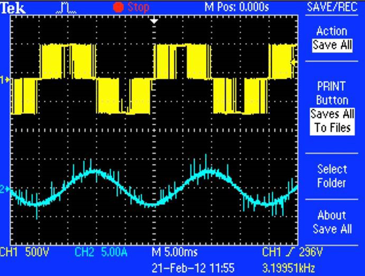
In commercial inverters the switching frequency is high and the measurement and interpretation of the actual waveforms is not straightforward. For example, the voltage and current waveforms in Fig. 7.9 relate to an industrial drive with a 3 kHz switching frequency. Note the blurring of the individual voltage pulses (a result of sampling limitations of the oscilloscope), and the near-sinusoidal fundamental component of current. We might be concerned at what appear to be spikes of current, but consideration of the motor leakage inductance and the limited forcing voltage will confirm that such rapid rates of change of current are impossible: the spikes are in fact the result of noise on the signal from the current transducer.
Measurement of almost all quantities associated with power electronic converters is difficult, and great care must be taken in the selection of instrumentation and interpretation of the results. A clear understanding of grounding is also important when reviewing inverter d.c. link and output waveforms since unlike a utility supply there is no clear, or at least simple, ground reference.
7.3.2 Current source induction motor drives
Although the majority of inverters used in motor drives are Voltage Source Inverters (VSI), described in Chapter 2 and discussed in the previous section, Current Source Inverters (CSI) are still sometimes used, particularly for high power applications, and warrant a brief mention.
The forced-commutated current-fed induction motor drive, shown in Fig. 7.10, was strongly favoured for single induction motor applications for a long period, and was available at power levels in the range 50–3500 kW at voltages normally up to 690 V. High voltage versions at 3.3 kV/6.6 kV were also developed but they have not proved to be economically attractive. Today it is not seen as having merit and has virtually disappeared from the portfolios of most companies. A brief description is included here for interest only.

The d.c. link current Id, taken from a ‘stiff’ current source (usually in the form of a thyristor bridge and a series inductor in the d.c. link), is sequentially switched at the required frequency into the stator windings of the induction motor. The capacitors and extra series diodes provide the mechanism for commutating the thyristors by cleverly exploiting the reversal of voltage resulting from resonance between the capacitor and the motor leakage reactance. The resultant motor voltage waveform is, perhaps somewhat surprisingly, approximately sinusoidal apart from the superposition of voltage spikes caused by the rise and fall of machine current at each commutation.
The operating frequency range is typically 5–60 Hz, the upper limit being set by the relatively slow commutation process. Below 5 Hz, torque pulsations can be problematic but PWM control of the current can be used at low frequencies to ease the problem.
This system was most commonly used for single motor applications such as fans, pumps, extruders, compressors, etc. where very good dynamic performance is not necessary and a supply power factor which decreases with speed is acceptable.
7.3.3 Performance of inverter-fed drives
It has often been said that the steady-state performance of the inverter-fed induction motor is broadly comparable with that of an industrial d.c. drive, but in fact the performance of contemporary inverter-fed induction motor is better in almost all respects.
To illustrate this, we can consider how quickly an induction motor drive, with field-oriented control (see Chapter 8), can change the motor shaft torque. Remarkably, the torque can be stepped from zero to rated value and held there in less than 1 ms, and this can now be achieved by a motor even without a speed/position sensor. For comparison, a thyristor-fed d.c. motor could take up to one sixth of a 50/60 Hz supply cycle i.e. around 3 ms before the next firing pulse can even initiate the process of increasing the torque, and clearly considerably longer to complete the task.
The induction motor is also clearly more robust and better suited to hazardous environments, and can run at higher speeds than the d.c. motor, which is limited by the performance of its commutator.
As we will see in Chapter 8, field-oriented control, coupled with the ability, through a PWM inverter, to change the stator voltage phasor in magnitude, phase and frequency very rapidly is at the heart of this exceptional motor shaft performance. The majority of commercial inverter systems now embody such control strategies, but the quantification of shaft performance is subject to a large number of variables and manufacturer's data in this respect needs to be interpreted with care. Users are interested in how quickly the speed of the motor shaft can be changed, and often manufacturers quote the speed loop response, but many other factors contribute significantly to the overall performance. Some of the most important, considering a spectrum of applications, are:
- • Torque Response: The time needed for the system to respond to a step change in torque demand and settle to the new demanded level.
- • Speed Recovery Time: The time needed for the system to respond to a step change in the load torque and recover to the demanded speed.
- • Minimum Supply Frequency at which 100% Torque can be achieved
- • Maximum Torque at 1 Hz
- • Speed Loop Response: This is defined in a number of different ways but a useful measure is determined by running the drive at a non-zero speed and applying a square wave speed reference and looking at the overshoot of speed on the leading edge of the square wave: an overshoot of 15% is—for most applications—considered practically acceptable. For the user, it is always a good idea to seek clarification from the manufacturer whenever figures are quoted for the speed (or current/torque) loop bandwidth of a digital drive, because this can be defined in a number of ways (often to the advantage of the supplier and not to the benefit of the application).
Note that the above measures of system performance should be obtained under conditions which avoid the drive hitting current limits, as this obviously limits the performance. Tests should typically be undertaken on a representative motor with a load inertia approximately equal to the motor inertia.
Indications of the performance of the open loop and closed loop field oriented induction motor control schemes are shown below:
| Open-loop(Without position feedback) | Closed loop(With position feedback) | |
|---|---|---|
| Torque response (ms) | < 0.5 | < 0.5 |
| Speed recovery time (ms) | < 20 | < 10 |
| Min speed with 100% torque (Hz) | 0.8 | Standstill |
| Max torque at 1 Hz (%) | > 175 | > 175 |
| Speed loop response (Hz) | 75 | 125 |
The performance of a closed loop inverter-fed induction motor is comparable to that of a closed loop permanent magnet motor, which we discuss in Chapter 9. This comes as a great surprise to many people (including some who have spent a lifetime in drives), possibly because the majority of induction motor drives use standard motors which were designed for fixed speed operation and broad application, whereas permanent magnet motors tend to be customised and many have been designed with relatively low inertias (long length and small diameter rotor), which facilitate rapid speed changes, or high inertias (short shaft and large diameter rotor) which promotes smooth rotation in the presence of load changes. Special induction motor designs are available, however, and are sometimes the preferred solution.
In the remainder of this section we give broad indications of the applicability of the various drive configurations that should prove helpful when looking at specific applications.
Open-loop (without speed/position feedback) induction motor drives
Open-loop induction motor drives are used in applications that require moderate performance (i.e. fans and pumps, conveyors, centrifuges, etc.). The performance characteristics of these drives are summarised below:
- • Moderate transient performance with full torque production down to approximately 2% of rated speed.
- • A good estimate of stator resistance improves torque production at low speeds, but the control system will work with an inaccurate estimate, albeit with reduced torque.
- • A good estimate of motor slip improves the ability of the drive to hold the reference speed, but the control system will work with an inaccurate estimate, albeit with poorer speed holding.
The performance of open loop induction motor drives continues to improve. Techniques for sensing the rotational speed of an induction motor without the need for a shaft-mounted speed or position sensor pervade the technical literature, and will in time find their way into some commercial drives.
Closed-loop (with speed/position feedback) induction motor drives
Induction motor drives with closed-loop control are used in similar applications to d.c. motor drives (i.e. cranes and hoists, winders and un-winders, paper and pulp processing, metal rolling, etc.). These drives are also particularly suited to applications that must operate at very high speeds with a high level of field weakening, for example spindle motors. The performance characteristics of these drives are summarised below:
- • Good dynamic performance at speeds down to standstill when position feedback is used.
- • Only incremental position feedback is required. This can be provided with a position sensor or alternatively a sensorless scheme can be used. The transient performance of a sensorless scheme will be lower than when a position sensor is used and lower torque is produced at very low speeds.
- • The robustness of the rotor makes induction motors particularly well suited to high speed applications that require field weakening. The motor current reduces as the speed is increased and the flux is reduced.
- • Induction motors are generally less efficient than permanent magnet motors because of their additional rotor losses.
Applications when field orientation or Direct Torque Control cannot be used
Field orientation and Direct Torque Control both rely upon modelling the flux in the motor. If a single inverter is being used to feed more than one motor, as in Fig. 7.11, neither control strategy can be used.
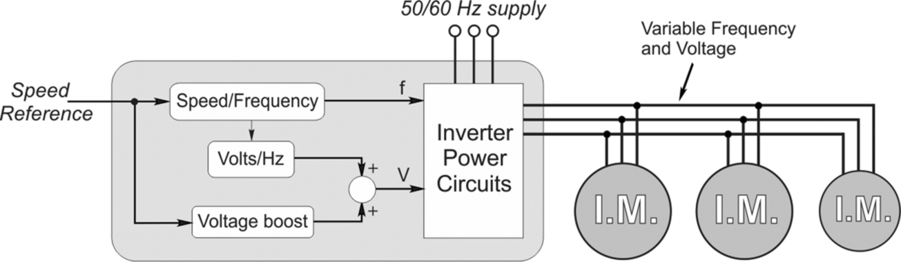
In such systems individual motor control is not possible and the only practical form of control is to feed the motor group with an appropriate voltage source, of which the magnitude and frequency can be controlled. In fact, this is exactly the traditional form of V/f control which predominated in early inverters. The output frequency, and hence the no-load speed of the motors, is set by the speed reference signal, (traditionally 0–10 V or 4–20 mA). In most automated applications the speed demand comes from a remote controller such as a PLC, while in simpler applications there will be a digital user interface on a control panel, or on the drive itself. The drive would have facility to adjust the V/f ratio, and to boost the voltage at low frequencies to compensate for the dominating influence of the stator winding resistance.
The fact that field orientation schemes use a vector modulator/PWM controller (see later Fig. 8.19) indicates that to adapt the field oriented scheme for multi-motor drives (i.e. a number of motors connected in parallel to a single inverter) is relatively simple: all that is required is to provide a sawtooth waveform of the appropriate frequency as input to the vector modulator (see Fig. 8.18). However, for Direct Torque Control schemes (see Chapter 8) there is no such controller, and in order to provide for multi-motor operation manufacturers employing this control strategy are obliged to provide an additional PWM controller.
7.4 Effect of inverter on the induction motor
It is often stated that standard ‘off-the-shelf’ a.c. motors can be used without problems with modern PWM inverters, and whilst such claims may be largely justified, inverters do have some impact and limitations are inevitable. In particular, the harmonic components of the voltages and currents create acoustic noise; they always give rise to additional iron and copper losses; and they have other effects which are perhaps less obvious. In addition, the operation of a standard motor—with its cooling system designed to suit fixed-speed operation—can be a significant limitation, and this will also be considered here.
7.4.1 Acoustic noise
Acoustic noise can usually be reduced by selecting a higher switching frequency (at the cost of higher inverter losses). It is interesting to note that not all motors exhibit the same characteristic when connected to identical inverters. The differences are usually small, and relate primarily to the clamping of the core iron in the stator of the motor. Certain switching frequencies may excite resonances in some motors, these often being related to the tie bars between the end frames: the vibrations can be alarming but easily remedied by changing the switching frequency, or, if the tie bar is external to the motor frame, by simply adding a wedge to change the natural frequency of the bar.
7.4.2 Motor insulation and the impact of long inverter-motor cables4
The PWM waveform has another very significant, but perhaps less obvious effect, related to the very high rates of change of voltage (dV/dt) which can result in damage to the winding insulation. In a modern 400 V (Silicon) IGBT power converter the d.c. link voltage is around 540 V, the voltage switches typically in 100 ns, and so at the terminal of the drive there is a very high dV/dt of over 5000 V/μs. (For Wide Band Gap devices using materials such as SiC and GaN, switching speeds are faster still.)
Recalling that the equation linking the current through and voltage across a capacitor is ![]() , it becomes clear that it is possible for appreciable current to flow in even a very small capacitance if the rate of change of voltage is high enough. In our context there are inevitably unwanted ‘stray’ capacitances within and between the phase-windings, and between the conductors in the supply cable and the cable screen or armouring. For example the capacitance of the cable to ground might be perhaps 100 pF/m, so a long cable of say 30 m would have a charging current pulse of 15A when the dV/dt was 5000 V/μs. However, as far as the charging current pulses are concerned, the issue is only likely to be a practical problem in small drives with very long motor cables, where the charging current pulses may, in extreme cases, exceed the rated current of the motor, and determine the rating of the required drive!
, it becomes clear that it is possible for appreciable current to flow in even a very small capacitance if the rate of change of voltage is high enough. In our context there are inevitably unwanted ‘stray’ capacitances within and between the phase-windings, and between the conductors in the supply cable and the cable screen or armouring. For example the capacitance of the cable to ground might be perhaps 100 pF/m, so a long cable of say 30 m would have a charging current pulse of 15A when the dV/dt was 5000 V/μs. However, as far as the charging current pulses are concerned, the issue is only likely to be a practical problem in small drives with very long motor cables, where the charging current pulses may, in extreme cases, exceed the rated current of the motor, and determine the rating of the required drive!
Very fast pulses take us from our familiar ‘low-frequency’ world into the territory of the communications or high-frequency engineer, where effects that we are usually unaware of begin to assert themselves. So whereas we can happily ignore the finite time taken for electrical effects to be transmitted from one part of a circuit to another, and hence are able to use simple lumped-parameter models (i.e. consisting of R, L, and C), these simplifications are inadequate at high frequencies. In essence, when the physical dimensions of the hardware become comparable with the wavelength of the electromagnetic phenomena, we have to resort to more elaborate distributed-parameter representations. A pulse travelling along our 50 m long drive to motor cable sees the cable as a transmission line along which energy travels at perhaps 60% of the speed of light, but nevertheless takes almost 300 ns to reach the motor. The so-called surge impedance of the cable is usually smaller than that of the motor, so a reflected pulse will be created, which in an extreme case could result in a doubling of the motor terminal voltage. The fast risetime pulses can also result in uneven voltage distribution within the motor windings, and consequent additional stressing of the insulation.
In case all this sounds alarming the fact is that such problems are extremely unusual and usually associated with systems employing old or very low cost motors with poor insulation systems, and/or with drive systems with rated voltages over 690 V. Naturally enough, the problem is more pronounced on medium voltage drives where it is not uncommon for dV/dt filters to be fitted between the inverter and the motor.
These phenomena are now very well understood by reputable motor manufacturers. International standards on appropriate insulation systems have also been published, notably IEC 34-17 and NEMA MG1pt31.
7.4.3 Losses and impact on motor rating
Operation of induction motors on an inverter supply inevitably results in additional losses in the machine as compared with a sinusoidal utility supply. These losses fall into three main categories:
- (a) Stator Copper Loss—This is proportional to the square of the r.m.s. current although additional losses due to skin effect associated with the high frequency components also contribute. We have seen in Fig. 7.1 that the motor current is reasonably sinusoidal and hence, as we would expect, the increase in copper loss is seldom significant.
- (b) Rotor Copper Loss—The rotor resistance is different for each harmonic current present in the rotor due to skin effect (and is particularly pronounced in deep bar rotors). Since the rotor resistance is a function of frequency, the rotor copper loss must be calculated independently for each harmonic. Whilst these additional losses used to be significant in the early days of PWM inverters with low switching frequencies, in modern drives with switching frequencies above 3 kHz the additional losses are minimal.
- (c) Iron Loss—This is increased by the harmonic components in the motor voltage.
For PWM voltage source inverters using sinusoidal modulation and switching frequencies of 3 kHz or higher, the additional losses are therefore primarily iron losses and are generally small, resulting in a loss of motor efficiency by 1–2%. Motors designed for enhanced efficiency, e.g. to meet the IEC IE2/IE3 requirements or NEMA EPACT and Premium Efficiency requirements, also experience a proportionately lower increase in losses with inverter supplies because of the use of reduced-loss magnetic steels.
However, the increase in losses does not directly relate to a de-rating factor for standard machines since the harmonic losses are not evenly distributed through the machine. The harmonic losses mostly occur in the rotor and have the effect of raising the rotor temperature. Whether or not the machine was designed to be stator critical (stator temperature defining the thermal limit) or rotor critical, clearly has a significant impact on the need for, or magnitude of, any de-rating. The cooling system (see below) is at least as important, however, and in practice it emerges that a standard motor may have to be de-rated by 5 or even 10% for use on an inverter supply.
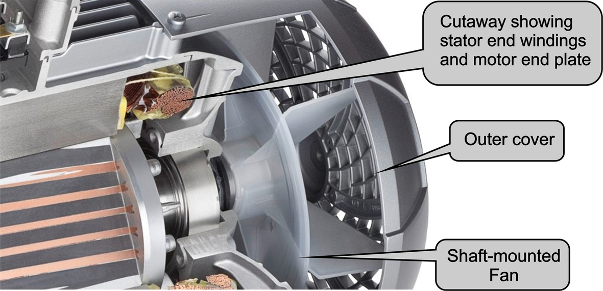
Whereas a d.c. motor was invariably supplied with through ventilation provided by an auxiliary blower, to allow it to operate continuously at low speeds without overheating, the standard induction motor has no such provision. Having been designed primarily for fixed-frequency/full-speed operation, most induction motors tend to be totally enclosed (IP44 or IP54) with a shaft-mounted fan at the non-drive end running within a cowl to duct the cooling air over a finned motor body as shown in Fig. 7.12. Note also the cast ‘paddles’ on the rotor endrings which provide internal air circulation and turbulence to assist with transmitting the heat from the rotor to the stator housing and from there to the atmosphere.
Thus although the inverter is capable of driving the induction motor with full torque at low speeds, continuous operation at rated torque is unlikely to be possible because the standard shaft mounted cooling fan will be less effective at reduced speed and the motor will overheat. We should say, however, that for applications such as fans and pumps where the load torque is proportional to the cube of the speed, no such problems exist, but for many applications it is a significant consideration.
7.4.4 Bearing currents
Scare stories periodically appear in the trade press and Journals relating to motor bearing failures in inverter-fed a.c. motors. It should be said immediately that such failures are rare, and mainly associated with medium voltage systems.
With a balanced three phase sinusoidal supply the sum of the three stator currents in an a.c. motor is zero and there is no further current flow outside the motor. In practice however there are conditions which may result in currents flowing through the bearings of a.c. motors even when fed with a sinusoidal 50 Hz or 60 Hz supply, and the risk is further increased when using an inverter supply. Any asymmetric flux distribution within an electrical machine can result in an induced voltage from one end of the rotor shaft to the other. If the bearing ‘breakover voltage’ is exceeded (the electrical strength of the lubricant film being of the order of 50 V) or if electrical contact is made between the moving and fixed parts of the bearing this will result in a current flowing through both bearings. The current is of low (often slip) frequency and its amplitude is limited only by the resistance of the shaft and bearings, so it can be destructive. In some large machines it is common practice to fit an insulated bearing, usually on the non-drive end, to stop such currents flowing.
Any motor may also be subject to bearing currents if its shaft is connected to machinery at a different ground potential from the motor frame. It is therefore important to ensure that the motor frame is connected through a low-inductance route to the structure of the driven machinery. This issue is well understood and with modern motors such problems are rare.
7.4.5 ‘Inverter grade’ induction motors
Addressing the above potential hazards, induction motors carrying the name ‘inverter grade’ or similar are readily available. They would typically have reinforced winding insulation systems and have a thermal capacity for a constant torque operating range, often down to 30% of base speed, without the need for additional external cooling. Further they would have options to fit thermocouples, a separate cooling fan (for very low speed operation) and a speed/position feedback device.
International standards exist to help users and suppliers in this complex area. NEMA MG1-2016, Part 31 gives guidance on operation of squirrel cage induction motors with adjustable-voltage and adjustable-frequency controls. IEC 60034-17 and IEC 60034-25 give guidance on the operation of induction motors with converter supplies, and design of motors specifically intended for converter supplies, respectively.
7.5 Utility supply effects
It is a common misconception to believe that the harmonic content of the motor current waveform and the motor power factor are directly reflected on the utility supply, but this is not the case. The presence of the inverter, with its energy-buffering d.c. link capacitor results in near unity power factor as seen by the utility supply regardless of load or speed of operation, which is of course highly desirable. It is not all good news however, so we now look at the adverse impact of an inverter- fed drive on the utility.
7.5.1 Harmonic currents
Harmonic current is generated by the input rectifier of an a.c. drive shown in Fig. 7.8. The utility supply is rectified by the diode bridge, and the resulting d.c. voltage is smoothed by the d.c. link capacitor and, for drives rated typically at over 2.2 kW, the d.c. current is smoothed by an inductor in the d.c. circuit. The d.c. voltage is then chopped up in the inverter stage which uses PWM to create a sinusoidal output voltage of adjustable voltage and frequency.
Whilst small drive ratings may have a single phase supply, we will consider a three phase supply. We see from Fig. 7.13 that current flows into the rectifier as a series of pulses that occur whenever the supply voltage exceeds that of the d.c. link, which is when the diodes start to conduct. The amplitude of these pulses is much larger than the fundamental component, which is shown by the dotted line.
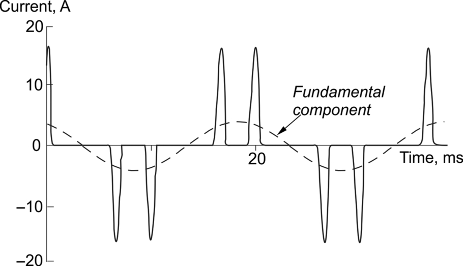
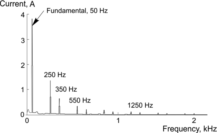
Fig. 7.14 shows the spectral analysis of the current waveform in Fig. 7.13.

Note that all currents shown in spectra comprise lines at multiples of the 50 Hz utility frequency. Because the waveform is symmetrical in the positive and negative half-cycles, apart from imperfections, even order harmonics are present only at a very low level. The odd order harmonics are quite high, but they diminish with increasing harmonic number. For the three phase input bridge there are no triplen (triple-frequency) harmonics, and by the 25th harmonic the level is negligible. The frequency of this harmonic for a 50 Hz supply is 1250 Hz which is in the audio frequency region of the electromagnetic spectrum and well below the radio frequency part which is generally considered to begin at 150 kHz. This is important, because it shows that supply harmonics are low frequency effects, which are quite different from radio frequency electromagnetic compatibility (EMC) effects. They are not sensitive to fine details of layout and screening of circuits, and any remedial measures which are required use conventional electrical power techniques such as tuned power factor capacitors and phase-shifting transformers. This should not be confused with the various techniques used to control the radio-frequency interference from fast switching devices, sparking electrical contacts, etc.—all matters that relate to the ‘high-frequency world’ referred to in Section 7.4.2.
The actual magnitudes of the current harmonics depend on the detailed design of the drive, specifically the values of d.c. link capacitance and, where used, d.c. link inductance, as well as the impedance of the utility system to which it is connected, and the other non-linear loads on the system.
We should make clear that industrial problems due to harmonics are unusual, although with the steady increase in the use of electronic equipment, they will become more common in future. Problems have occurred most frequently in office buildings with a very high density of personal computers, and in cases where most of the supply capacity is used by electronic equipment such as drives, converters and UPS.
As a general rule, if the total rectifier loading (i.e. drives, UPS, PCs, etc.) on a power system comprises less than 20% of its current capacity then harmonics are unlikely to be a limiting factor. In many industrial installations the capacity of the supply considerably exceeds the installed load, and a large proportion of the load such as uncontrolled (direct on line) induction motors and resistive heating elements generate minimal harmonics.
If rectifier loading exceeds 20% then a harmonic control plan should be in place. This requires some experience and guidance can often be sought from equipment suppliers. The good news is that if it is considered that a problem will exist with the estimated level of harmonics then there are a number of options available to reduce the distortion to acceptable levels.
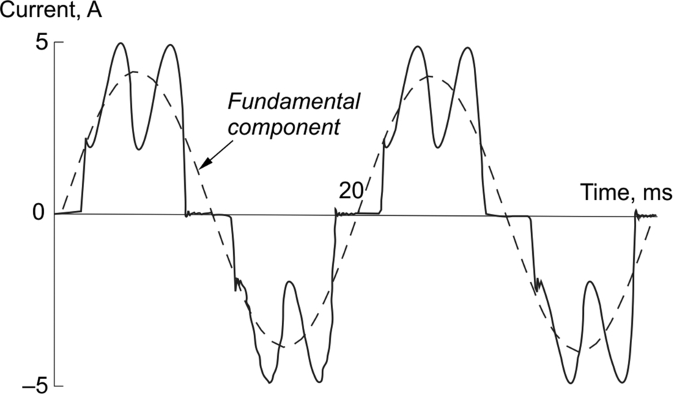
A.C. drives rated over 2.2 kW tend to be designed with inductance built in to the d.c. link and/or the a.c. input circuit. This gives the much better supply current waveform and its dramatically improved spectrum as shown in Figs. 7.15 and 7.16 respectively, which are again for a 1.5 kW drive for ease of comparison with the previous illustrations. (In this case the inductance in each line is specified as ‘2%’, which means that when rated fundamental current flows in the line, the volt-drop across the inductor is equal to 2% of the supply voltage.) Note the change of vertical scale between Figs. 7.13 and 7.15, which may tend to obscure the fact that the pulses of current now reach about 5 A, rather than the 17 A or so previously, but the fundamental component remains at 4 A because the load is the same. (Remember that whilst we have just demonstrated the tremendous improvement in supply harmonics achieved by adding d.c. link inductance to a 1.5 kW drive, standard drives would rarely be manufactured with any inductance because whilst the harmonic spectrum looks worrying, the currents are at such a low level that they would rarely cause practical problems.)
Standard three phase drives rated up to about 200 kW tend to use conventional 6 pulse rectifiers. At higher powers, it may be necessary to increase the pulse number to improve the supply-side waveform, and this involves a special transformer with two separate secondary windings, as shown for a 12-pulse rectifier in Fig. 7.17.
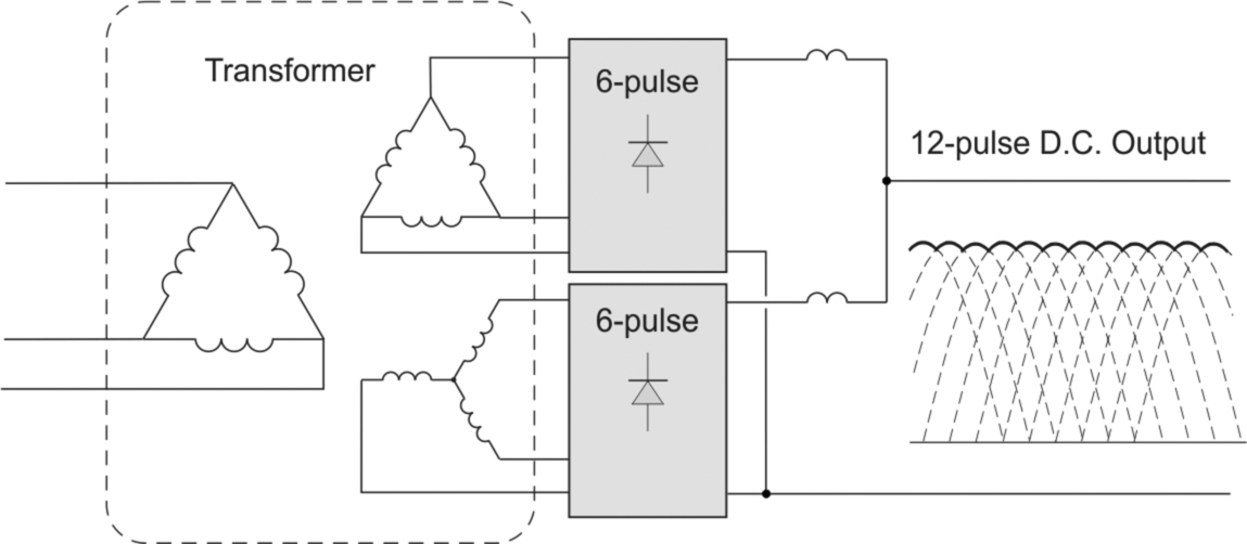
The voltages in the transformer secondary star and delta windings have the same magnitude but a relative phase shift of 30°. Each winding has its own set of six diodes, and each produces a six-pulse output voltage. The two outputs are generally connected in parallel, and because of the phase shift, the resultant voltage consists of twelve pulses of 30° per cycle, rather than the six pulses of 60° shown for example in Fig. 2.13.
The phase shift of 30° is equivalent to 180° at the fifth and seventh harmonics (as well as 17, 19, 29, 31, etc.), so that flux and hence primary current at these harmonics cancels in the transformer, and the resultant primary waveform therefore approximates very well to a sinusoid, as shown for a 150 kW drive in Fig. 7.18.

The use of drive systems with an input rectifier/converter using PWM which generates negligible harmonic current in the utility supply, as described in Section 2.4.6, is becoming increasingly common. This also permits the return of power from the load to the supply.
7.5.2 Power factor
The power factor of an a.c. load is a measure of the ratio of the average power to the product of r.m.s. current and voltage, and is given by:

With a sinusoidal supply voltage and a linear load the current will also be sinusoidal, with a phase-shift of ϕ with respect to the voltage. The power is then given by the simple expression
where V and I are r.m.s. values (which are equal to the peak of the sinusoid divided by √ 2), and so in this case the power factor is equal to cos ϕ. Clearly the maximum possible power factor is 1.
Unfortunately, in power electronic circuits either the voltage or the current or both are non-sinusoidal, so there is no simple formula for the r.m.s. values or the mean power, all of which have to be found by integration of the waveforms. There is therefore no simple formula for the power factor, but frequent use is made of a related quantity known as the fundamental power factor, given by

The influence of the harmonics in the non-sinusoidal waveforms causes the actual power factor to be lower than the fundamental power factor, so users should be aware that when suppliers quote the power factor of a drive they are usually ignoring the harmonic currents, and quoting cos φ, the fundamental power factor.
It may be worth reminding readers who are not familiar with industrial energy tariffs why maximising the power factor is important. All industrial users pay primarily for the energy used, which depends on the integrated total of the product of power and time, but most are also penalised for drawing the power at a low power factor (because the currents are higher and therefore switchgear and cables have to be larger than would otherwise be necessary). In addition, there may be a penalty related to the maximum VoltAmpere product in a specified period, so again a high power factor is desirable.
Fortunately, for the diode bridge, which is the most common form of rectifier in a commercial a.c. drive, cos ϕ is close to unity for all speed and load conditions. To illustrate this, we can consider a typical 11 kW induction motor operating at full load, connected either directly to the utility supply or through an a.c. variable speed drive. Comparative figures are given in the table below.
| At supply terminals | Direct on line motor | Motor viaa.c. drive | Notes on drive parameters |
|---|---|---|---|
| Voltage (V) | 400 | 400 | |
| r.m.s. current (A) | 21.1 | 21.4 | No significant change. |
| Fundamental current (A) | 21.1 | 18.8 | Reduced because magnetising current is not drawn directly from the utility supply. |
| Fundamental power factor (cosφ) | 0.85 | 0.99 | Improved because input rectifier current is in phase with supply voltage. |
| Power (W) | 12,440 | 12,700 | Slight increase at full load due to drive losses. |

A typical PWM induction motor drive improves the power factor as compared with a direct on line motor because it reduces the requirement of the supply to provide the magnetising current for the motor, but in return generates harmonics. Power consumption at full load is slightly increased due to losses of the drive.
7.6 Inverter and motor protection
We have stressed before that power semiconductors are notoriously intolerant of excess current, and so even in the earliest drives of this type, current was measured in order to trip the drive when a simple current threshold was exceeded and before damage could be done to the inverter. Some protection schemes would also sense high currents and reduce the applied frequency and thereby reduce the current.
The stored energy in the drive and motor inductances and capacitances also needs to be handled without inducing voltages or currents which can damage the system components. As previously mentioned, the basic power circuit is not inherently capable of regenerating energy back into the supply, and when a braking duty results in energy flow into the d.c. link then a correctly-rated ‘dump resistor’ (see Section 2.4.5) must be provided in order to limit the circuit voltages.
Motor protection also requires current measurement, but here it is thermal protection of the motor that is of concern. A very approximate indication of the losses or heating effect in the motor is obtained by monitoring the product of the square of the motor current times time. This so-called ‘i2t’ protection is still referred to as motor thermal protection in drives, though many of the thermal algorithms now employed are very much more complex and accurate than their primitive predecessors.
Modern commercial drives include extensive internal protection systems as well as thermal motor modelling systems, but such drives are designed for a multiplicity of applications and motor designs and so must be configured during installation. Where multiple motors are fed from a single inverter (as described in Section 7.3.3) each motor must have its own individual thermal trip, because the fault current of any individual motor alone may not be significant when a large number of motors are connected to the same inverter.
7.7 Review questions
- (1) Choose a suitable pole-number for an induction motor to cover the speed range from 400 rev/min to 800 rev/min when supplied from a 30–75 Hz variable-frequency source.
- (2) A 2-pole, 440 V, 50 Hz induction motor develops rated torque at a speed of 2960 rev/min; the corresponding stator and rotor currents are 60 A and 150 A, respectively. If the stator voltage and frequency are adjusted so that the flux remains constant, calculate the speed at which full torque is developed when the supply frequency is (a) 30 Hz, (b) 3 Hz.
- (3) Estimate the stator and rotor currents and the rotor frequency for the motor in question 3 at 30 Hz and at 3 Hz.
- (4) What is ‘voltage boosting’ in an open loop voltage-source inverter, and why is it necessary?
- (5) An induction motor with a synchronous speed of Ns is driving a constant-torque load at base frequency, and the slip is 5%. If the frequency of the supply is then doubled, but the voltage remains the same, estimate the new slip speed and the new percentage slip.
- (6) Approximately how would the efficiency of an inverter-fed motor be expected to vary between full (base) speed, 50% speed and 10% speed, assuming that the load torque was constant at 100% at all speeds and that the efficiency at base speed was 80%.
- (7) Why is it unwise to expect a standard induction motor driving a high-torque load to run continuously at low speed?
- (8) Explain briefly why an inverter-fed induction motor will probably be able to produce more starting torque per ampere of supply current than the same motor would if connected directly to the utility supply. Why is this likely to be particularly important if the supply impedance is high?
- (9) Why is the harmonic content of an inverter-fed induction motor current waveform less than the harmonic content of the voltage waveforms?
Answers to the review questions are given in Appendix.