
Standard Interfaces
Abstract
A number of interface standards have been developed for computing systems. Many of these standards are useful for embedded computing. We review the organization of the Open Systems Interconnection (OSI) and then describe several useful embedded system interface standards, including I2C, USB, WiFi, Zigbee, Bluetooth, and BLE. We discuss the implications of Internet-enabled embedded devices that make use of standard interfaces.
Keywords
Standards; Physical layer; Data link layer; Network layer; I2C; USB; WiFi; Zigbee; Bluetooth; BLE; Internet
2.1 Introduction
A number of interfacing standards are in daily use. Standards such as I2C or USB have been built into many components and systems. Typically, using them requires no hardware design and limited software design. Understanding how these interfaces work is very useful. Their principles also help us understand the role of interfaces in embedded systems.
The Open Systems Interconnection (OSI) model, shown in Fig. 2.1 is widely used to describe the design of computer networks. The model includes several layers that start at the most basic physical characteristics at layer 1 up to the application in layer 7. This chapter concentrates on the bottom three layers, known as the media layers:
- • Layer 1, the physical layer (PHY), includes the physical and electrical characteristics of the connection. Physical characteristics include, for example, the type of connector used. Electrical characteristics describe the signals used for data.
- • Layer 2, the data link layer, describes the basic transfer of data from one network node to another. The unit of transfer at this level is the frame. This layer is divided into two sublayers. This layer is divided into two sublayers: the media access control (MAC) layer controls how devices can gain access to the communications medium; the logical link control (LLC) layer identifies and encapsulate protocols at the network layer as well as managing error correction and frame synchronization.
- • Layer 3, the network layer, moves data sequences from one node to another, potentially across several different types of networks.

In this chapter, we will look at six different standard interfaces:
- • The RS-232 serial interface commonly used on personal computers.
- • The I2C interface which is used to communicate with devices along a relatively simple bus; we also discuss the I2S bus used for digital audio and the CAN bus used in automotive systems.
- • The Universal Serial Bus (USB), which has gone through several revisions as a common standard for PC interfacing.
- • WiFi, a wireless network widely used for PCs and also for IoT systems.
- • Zigbee, a wireless network designed for embedded systems.
- • Two wireless interfaces, Bluetooth and Bluetooth Low Energy (BLE). Despite sharing a common root name, these two interfaces vary in some interesting and important ways.
- • LoRaWAN, a low power wide area network.
In Section 2.9, we will consider Internet connections that rely on communications interfaces.
2.2 RS-232
Serial interfaces are some of the oldest computer interfaces, predating many features of modern computer systems, including the OSI model. A number of different serial interfaces and protocols have been defined over the years. The RS-232 standard was created in 1960 and was provided on most personal computers for many years. Today, few PCs provide a serial port but RS-232 is still used in some types of industrial equipment. Serial ports do not run at high speeds by modern standards but their hardware and software requirements are both minimal.
Fig. 2.2 shows a typical early use case for RS-232 connections; this configuration helps explain some of the terminology used in the standard. When a computer was the size of a room, users often sat elsewhere and connected to the computer over serial lines. Modems were used to transmit data over the phone line. RS-232 links were used to connect the modems to the computer and terminal, respectively. In this scenario, the terminal is data terminal equipment (DTE) and the modem is data circuit-terminating equipment (DCE).

The RS-232 electrical standard uses much higher voltages than are typically used today. Those high voltages often require specialized circuits; however, they do provide some amount of resistance to noise in challenging environments. The standard allows signals of up to 25 V; both positive and negative voltages are used and voltages around ground are not valid levels. The mark data signal is sent as a low voltage level while the space is a high voltage level.
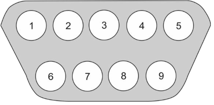
Fig. 2.3 shows the 9-pin D-sub connector used for serial ports. This connector is an example of the mechanical specification required for interfacing—users must be able to plug into the connector. The nine pins are used for various signals:
- • Pin 1: data carrier detect (DCD).
- • Pin 2: serial data input (RxD).
- • Pin 3: serial data output (TxD).
- • Pin 4: data terminal ready (DTR).
- • Pin 5: ground (GND).
- • Pin 6: data set ready (DSR).
- • Pin 7: request to send (RTS).
- • Pin 8: clear to send (CTS).
- • Pin 9: ring indicator (RI).
TxD and RxD are the data transmit and receive lines, respectively. These directions are defined from the terminal or computer: transmit goes from a terminal to a modem, for example. A null modem is a device with two connectors that swaps the transmit and receive lines from one connector to the other.
Fig. 2.4 character shows the form of a character on an RS-232 connection. Transmit and receive rates are controlled by their own clocks; these clocks are considerably slower than the clocks used in typical logic. A character starts with a start bit, which is always a low voltage and lasts for one bit period. Data bits follow, followed by a parity bit. The character ends with a stop bit, which is at least the length of one bit and may last up to two bits.

Parity provides simple error detection. A parity bit is added to the character; the value of the parity bit depends on the bits in the character. First, we perform the exclusive-OR of all the character bits. We then have two possible protocols to follow: even parity sets the parity bit so that the exclusive-OR of the data plus parity bits is even (0); odd parity sets the parity bit to give an odd result (1). The receiver can compute the exclusive-OR of the bits it received; it has earlier agreed on the even/odd protocol to be used. If the parity of the received character does not match the specified parity, the receiver can signal an error.
We can study the 8251A data sheet to understand the RS-232 signals. A few terms are useful. Baud rate is the rate at which symbols are sent; the bit rate is the rate at which bit values are transmitted. If the communications medium can encode more than one symbol in a bit, then the bit rate is higher than the baud rate. Mark and space are used to describe logic 1s and 0, respectively. A typical RS-232 connection would include a computer one end, a terminal on the other, and a modem in between.
DSR’ is the logically inverted form of data set ready provided by the 8251. The CPU can test this signal to determine if the modem is ready to operate. DTR’ is also logically inverted; it indicates whether the terminal is ready.
The roles of RTS and CTS have changed over time. Originally, they were used to switch the direction of data; the relatively simple modems of the time could move data in only one direction over time. Eventually, modems became more sophisticated and devices became able to send larger blocks of data. As a result, RTS and CTS became used for flow control. A flow control protocol, shown in Fig. 2.5, is a form of handshaking that is used to manage rates and avoid overrunning buffers. The transmitter and receiver are each controlled by their own state machine; the interaction between these state machines defines the protocol. The transmitter responds to an internal go signal to start the transmission process. It sends an RTS signal high and waits for the receiver to return with CTS. It sends the required data bits; when it is done, it deasserts RTS (i.e., sets RTS low), then waits for the receiver to deassert CTS. The receiver runs concurrently. When it receives an RTS, it waits for an internal OK signal before signaling, using the CTS signal, that it is ready to receive. It receives bits, then expects the transmitter to deassert RTS, at which point it deasserts CTS. Each side of the transaction has moved through its four states to return to the initial state, leaving each side ready for another character. The ready to receive (RTR) signal found in later versions of the RS-232 standard shares the same pin as RTS but are used for this flow control operation. The ring indicator signal can be used by the modem to tell the terminal or computer that the phone line is ringing. The C/D line is used to indicate whether the bus contains data or a command.

One common way to build an RS-232 interface is by using particular chip, the Intel 8251A. The 8251A design was later offered by other manufacturers as its popularity spread. The 8251A was designed to be able to implement a number of existing serial communication standards; it is flexible but the designer was largely responsible for harnessing that flexibility into a usable serial link.
Fig. 2.6 shows a block diagram of the signals on the 8251A. The signals on the left side go to the computer while those on the right side go to the serial line. Several of these CPU signals correspond to RS-232 signals: DSR, DTR, CTS, and RTS are all given in negative form. Data is supplied on eight parallel, bidirectional lines. The C/D’ signal is used to determine whether the data lines represent data (0) or control (1) information. The reset signal allows the chip to be reset. CLK provides the clock. RD’ and WR’ are used to tell the 8251A that the CPU is reading or writing words. On the serial line side, we have transmitted serial signals. TxD is transmitting data, TxRDY signals whether the transmitter is ready, TxE signals that the transmitter has no characters ready to send. TxC’ is a clock used to determine the rate of the data symbols. RxD is the receive data, RxRDY indicates that the receiver is ready, RxC’ is the receive data clock. The SYNDET/BRKDET signal is used as either an output (sync detect) or an input (break detect).

The 8251A has seven internal eight-bit registers. Two of the registers—the transmit and receive buffers—are used for the data that is transmitted or received. The sync1 and 2 characters are used in synchronous mode only. The status register gives status and error information. The mode register determines whether synchronous or asynchronous mode will be used along with their parameters. The command register is used for enabling, disabling, and error handling.
After the 8251A is reset, the CPU needs to send two words: first, a mode instruction which specifies synchronous or asynchronous along with some operating parameters; next, a command instruction which sets up the transmit and receive modes.
The mode instruction bits are used as follows:
- • Bits 0-1 specify the baud rate factor: synchronous mode (00), 1X (01), 16X (10), or 64X (11). This factor determines the conversion rate between the mark/space rates and the transmit or receive clocks.
- • Bits 2-3 specify the character length: 5 (00), 6 (01), 7 (10), or 8 (11) bits.
- • Bits 4-5 specify parity: even (11), odd (00), or disabled (10, 01).
- • Bits 6-7 specify the length of the stop bit: 1 (01), 1.5 (10), or 2 (10).
The command register bits include:
- • Bit 0, TXEN, enables (1) or disables (0) the transmitter.
- • Bit 1, DTR sends an nDTR output value in negated form (1 for 0, 0 for 1).
- • Bit 2, RXE, enables (1) or disables (0) the transmitter.
- • Bit 3, SBRK, sends a break character (1) or specifies normal operation (0).
- • Bit 4, ER, sets (1) or keeps (0) error flags.
- • Bit 5, RTS, sets an nRTS value in negated form.
- • Bit 6, IR, performs an internal reset (1) or normal operation (0).
- • Bit 7, EH, enables hunt mode (1), or normal operation.
The status bits include:
- • Bit 0, TXRDY, signals whether the transmitter is busy (0) or ready (1).
- • Bit 1, RXRDY, signals whether the receiver is busy (0) or ready (1).
- • Bit 2, TXEMPTY, indicates whether the transmitter is busy (0) or done (1).
- • Bit 3, PE, indicates a parity error (1) or OK (0).
- • Bit 4, OE, indicates an overrun error (1) or OK (0).
- • Bit 5, FE, indicates a frame error (1) or OK (0).
- • Bit 6, SYNDET, indicates whether a sync char was detected (1).
- • Bit 7, DSR, indicates the DSR value in negated form.
One of the charms of RS-232 is that it is slow and simple enough that we can watch it operate. A breakout box is a simple device with a pair of D-sub connectors. The RS-232 signals flow through but they are also shown on LEDs. The data is usually too fast to read directly but the control signals can be seen; watching them allows us to see how the serial line is operating.
2.3 I2C, CAN, and I2S
I2C [45] is widely used to connect multiple chips in systems. The bus provides relatively low data rates, so its uses are primarily for mode control and similarly low-speed uses. However, its extremely low cost has helped to make it ubiquitous. The CAN bus [8] is widely used in automotive electrical and electronics (EE) systems. Its structure is very similar to I2C.
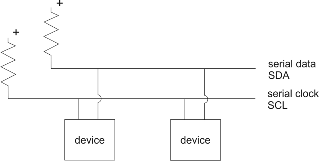
The physical layers of I2C are very simple. As shown in Fig. 2.7, the serial bus includes two wires: serial data (SDA) and serial clock (SCL). Each line is connected to a pullup resistor. When a device wants to send a zero on either wire, it turns on a transistor to pull down the wire. When no device wants to transmit a zero, the pullup resistor ensures that the wire's value remains high. This arrangement ensures that conditions which cause two devices to try to write at the same time do not damage the bus; it also ensures that the bus signal always carries a valid logic value. The standard provides for several modes that run at different rates: 100 kbit/s for standard mode, 400 kbit/s for fast mode, 1 Mbit/s in fast mode plus, and 3.4 Mbit/s in high speed mode. The logic levels for standard mode put − 0.5 V ≤ VIL ≤ 0.3 V, VIH ≥ 0.7 V. The standard move allows for a maximum clock frequency of 100 kHz.
The CAN bus uses a similar physical layer that can transmit at 1 Mb/s over a maximum length of 50 m; a variation using an optical link has also been developed.
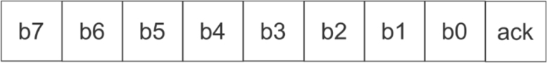
All data is sent as eight-bit bytes. As shown in Fig. 2.8, the data is transmitted from most-significant bit (MSB) to least-significant bit (LSB). The receiving slave acknowledges each bite: the master temporarily releases SDA; the slave pulls SDA low for an acknowledgment or leaves it high for a negative acknowledgment.
As shown in Fig. 2.9, a data transfer consists of a start bit, a sequence of bytes, and a final stop bit. A start bit is signaled by a high-to-low transition on SDA while a stop bit is signaled by a low-to-high transition on SDA. The first part of the data transfer is the address, plus a read/write bit. This figure shows the original 7-bit address mode: the first seven bits of the first byte are address, with the eighth bit indicating read/write’. A 10-bit address mode uses the first two bytes for address and read/write’; the high-order five bits of the high address byte are 11,110. A master can generate successive data transfers by sending another start signal without having sent a stop; this feature allows the master to send to several different slaves without the overhead of intermediate stop bits.

Because the bus may have more than one master, mastership must be arbitrated to determine who can transmit. Unlike some busses, arbitration occurs during the transmission of the address bit. The protocol takes advantage of the physical layer design to simplify arbitration. A device may start to write when the bus is inactive. When two devices try to write at the same time, each cannot tell that another device is trying to transmit until the two devices try to send different bits. Both devices monitor the bus as they transmit. When they detect a conflict, the device with the lower priority immediately stops transmitting. The bus clock is slow enough that the valid bit can be properly transmitted during the remainder of the clock period. The standard reserves some addresses, including a general call address. Sending a general call, followed by a second byte value of 00000110 signals a software reset. CAN uses a similar arbitration method. Nodes listen to the bus to determine when a new transmission begins.
Devices typically come from the manufacturer with a default address. Some devices do not allow the address to be changed at all; others allow a limited range of address reprogramming; some allow for arbitrary reprogramming of the address. If the device does not provide for sufficient address reprogramming, a common solution is to assign each device a unique identifier in the data section of the device. Each data transfer to this class of device starts with the device address, followed by a byte which gives the identifier for which the transfer is intended. This solution comes at the cost of bus bandwidth.
The I2S bus [47] has a very similar name and was developed by the same company but is used for very different purposes. This bus is one of several designed solely as a streaming audio interface for communication between chips in consumer audio systems. The bus includes three lines: clock SCK, word select WS, and data SD. Word select is used to indicate whether the data is for the left or right channels, implicitly limiting the standard to stereo. Any device that drives the clock effectively serves as master but the standard provides no mechanism for switching between bus masters.
2.4 USB
The Universal Serial Bus, more commonly known as USB, is used in billions of computing devices. Given its ubiquity in computing, it should be no surprise that it is used for embedded system interfacing, either to connect to a host PC or to connect the embedded computer to other devices.
USB [14, 26] has evolved over several versions over the past two decades, offering higher performance and other features over time. USB 1.1 ran at 12 Mbit/s, USB 2.0 at 480 Mbit/s, USB 3.0 at 5 Gbit/s, USB 3.1 at 10 Gbit/s, and USB 3.2 at 20 Gbit/s.
From the point of view of applications running on the USB host, the devices on a USB bus provide functions to applications on the host. As shown in Fig. 2.10, each application deals with a function; it does not see the bus as a whole. The applications use USB application programming interfaces (APIs) to deal with the functions, not low-level device operations. We will discuss USB APIs in more detail later.

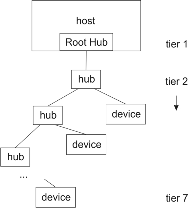
Physically, a USB bus is a tree as shown in Fig. 2.11. The host provides the root hub for the network; the host interface is known as the Host Controller. The root hub connects to one or more hubs which then connect to some combination of devices or other hubs. The bus may have at most seven tiers of devices, including the root hub. Logically, the USB bus appears as a bus—all devices and hubs see the same data traffic. However, the SuperSpeed connections in USB 3.x are not shared but rather point to point.
USB 2.0 uses a four-wire cable to connect the nodes of the network: a power signal Vbus, ground, and two data lines D + and D −. A clock is encoded along with the data. Differential signaling is used to improve noise immunity. The data signals use nonreturn to zero inverted (NRZI) encoding: no change in the signals indicates a 1 while a change indicates a 0. A clock can be extracted from the data stream at each end of the connection by monitoring the transitions. However, a long string of 1 s would result in no transitions, leaving the circuits no information from which to infer the clock. This problem is solved by bit stuffing: a zero is inserted after every string of six consecutive 1 s. The stuffed bit is then removed by the receiver. The Enhanced SuperSpeed USB 3.1 architecture adds four more lines for the high-speed data which flows separately from the low/full/high-speed data provided by USB 2.0. Data on the SuperSpeed path is encoded using an 8b/10/b encoding while SuperSpeedPlus uses a 128/132b encoding; these encodings provide a more sophisticated form of transition management for clock recovery.
Functions may be self-powered or draw power from USB. As the standard has grown, the power delivery capabilities of a connection have grown from relatively modest to very substantial: 0.5 W for USB 1.0, 2.5 W for USB 2.0, and 100 W in the new USB Power Delivery specification. (USB 2.0 did allow for a charging downstream port that was not compliant with the standard but could supply more power.) Enhanced SuperSpeed provides additional power management capabilities. Because the SuperSpeed data is routed to its destination, not broadcast, devices that are not the target of the communication can remain in a low-power state.
Fig. 2.12 shows the layer diagram for the host and device sides of a USB bus. On the host side, the client application logically interacts with the device's function layer. The host's USB system software layer and the USB logical device layer provide functions to perform the necessary operations on the host and device sides, respectively. The USB host controller and USB bus interface are physically connected on the USB bus to perform the required communication.

The host controller initiates all transfers. The bus protocol is based on polling. The protocol used to connect between the host and a function endpoint is known as a pipe. Pipes can be one of several types:
- • Stream pipes flow data from source to destination. The order of bytes is maintained and no structure is imposed by USB.
- • Message pipes operate on a request/data/status model and provide bidirectional communication.
A message pipe has a well-defined structure; a stream pipe does not. Pipes can be configured with bandwidth, transfer service type, and endpoint characteristics.
A device presents a set of endpoints to the host, each of which is a destination for communication. An endpoint provides several parameters to the application software to manage communication: endpoint number, bus access frequency and latency requirements, required bandwidth, maximum packet size, error handling, transfer type, direction of transfer. The Default Control Pipe is required to be endpoint zero on each device; it is used in status and control.
Transfers are one of four types:
- • Control transfers are host initiated and used for status queries and commands.
- • Isochronous transfers are periodic, streaming transfers.
- • Interrupt transfers provide bounded-latency communication and are intended to be used infrequently.
- • Bulk transfers are nonperiodic and intended for large data transfers that are not time sensitive.
If a device requires several different types of connections, each is established in a different pipe.
Communication on the bus is structured into packets. Bits are sent on the bus least-significant bit first; bytes are sent in little-endian order with the LSB first. A packet includes a SYNC field, a packet identifier (PID), a function address field, an endpoint field, a frame number field, a data field of length ranging from zero to 1024 bytes, and cyclic redundancy checks (CRCs) for tokens and data. A PID may be of one of four types: token, data, handshake, or special. Each type is subdivided into categories. Data is divided into frames or microframes in USB 2.0. A frame is marked by a Start-of-Frame (SOF) token on the bus. At full speed, SOF tokens are generated at 1 ms intervals; at high speed, they are generated at 125 μs intervals. Frame numbers are used to identify frames or microframes. A separate packet format is used for Enhanced SuperSpeed USB.
USB supports split transactions which separate the request from the response. Split transactions allow other devices to use the bus while the request is being processed.
A device can be in one of several states:
- • A device enters the attached state when it is connected to the USB bus.
- • When power is applied to the device, it is in the powered state.
- • When the device has been reset, it is in the default state.
- • Once an address has been assigned to the device by the Host Controller, it is in the address state.
- • After other required configuration operations have been performed, the device is in the configured state.
- • A device may be suspended, in which case the host may not use its function.
When a device is attached to the bus, the Host Controller enumerates the device:
- • The Host Controller receives an event on its status change pipe. The device is in the attached state.
- • The host queries the hub to determine the nature of the change and identify the port being used.
- • The host then waits for at least 100 ms as the device powers up. The device is in the powered state.
- • The host issues a reset command to the port. The device is in the default state.
- • The host uses the Default Control Pipe to determine the device's maximum data payload.
- • The host assigns a unique address to the device, putting the device in the address state.
- • The host reads the possible configurations of the device; it may have more than one possible configuration.
- • The host determines a configuration value for the device, based on the device's possible configurations and how it will be used. Once the device has finished its configuration process, it is in the configured state.
In addition to their particular functions, each USB device must provide several common operations:
- • Dynamic attachment and removal at any time.
- • Address assignment.
- • Configuration.
- • Data transfer.
- • Power management.
- • Power budgeting—the configuration process selects the power mode for the device in part based on the available power on the bus, given the power needs of other devices.
- • Remote wakeup to take a device out of its suspend state.
- • Request processing.
USB imposes some timing limits on operations: 5 s to process a command, 10 ms recover time between attachment to the bus and starting transfers; 50 ms for the Status stage of setting an address and 2 ms for recovery after setting the address; 50 ms for the Status stage of a device request with no Data stage; 500 ms to start data transfers for a request with data.
A hub connects one upstream port with several downstream ports. A hub includes of three major subsystems: the Hub Controller, the Hub Repeater, and the Transaction Translator.
The host is responsible for detecting when devices are attached and removed, managing control and data flow to and from the devices, collecting status and activity statistics, and providing power. These services are managed by the USB System Software which has three components: the Host Controller Driver, the USB Driver, and the Host Software or application. The Host Controller performs several types of operations:
- • Management and reporting of its own state.
- • Serializing output data and deserializing input data.
- • Generation of microframes.
- • Managing data requests to and from the host.
- • Performing the USB protocol operations.
- • Detecting and reacting to error messages.
- • Place the bus into a Suspended state and be able to wake up the bus.
- • Perform Root Hub functions.
- • Provide a Host System Interface.
2.5 WiFi
WiFi is the brand name for a set of wireless data standards. The standards are part of the IEEE 802.11 family. This set of standards defines MAC and PHY for wireless local area networks; the standards operate over several bands. Data rates depend on the member of the family; examples include at 6–54 Mbits/s and 802.11n at 54–600 Mbits/s.
Data is organized into frames consisting of a MAC header, payload, and frame check sequence. Management frames are used for maintenance operations.
WiFi was created for fixed and mobile computing applications which generally operate at higher power levels than do modern Internet-of-Things devices. Techniques have been developed to reduce the power consumption of WiFi for use in embedded applications.
2.6 Zigbee
Zigbee is a network- and application-level wireless standard. It makes use of PHY and MAC layers from the IEEE 802.15.4 standard. It provides data rates of up to 250 kbits/s.
Each Zigbee network has one Zigbee Coordinator (ZC) to form the root of the network. A Zigbee End Device (ZED) provides only basic functionality and cannot send or receive directly with other devices. A Zigbee Router (ZR) passes data between devices and/or the coordinator; it can also run applications. A network can run in either a beacon or beaconless mode. If operating in beacon-enabled mode, routers periodically transmit; devices may turn off in between beacon transmissions to save energy.
Zigbee adds two layers above the PHY and MAC layers supplied by 802.15.4: network data service (NWK) and application (APS). The PHY layer operates on packets while the MAC layer operates on frames.
The network layer provides data and management. The network layer discovers nodes in the network. It forms a network: it identifies a channel on which it can operate; it then assigns a 16-bit network address to each device in the network. Communication may be broadcast, multicast, or unicast. A network may be organized as a tree or a mesh. The network layer limits the number of hops, known as the radius, across which a frame may travel. The network layer is responsible for discovering routes through the network and building a routing table. After formation of the network, the coordinator manages the process of devices joining or leaving the network.
The application layer includes three major components. The application support (APS) sublayer interfaces to the network layer. The Zigbee Device Object (ZDO) is responsible for device management and services, including defining whether it operates as coordinator, router, or device. ZDO also manages security operations.
The application framework provides several services, including a message service for data transfers and a key-value pairs (KVPs) for service attributes. Application profiles can be used to manage the configuration of application; several profiles for common applications have been defined. A profile is named by a 16-bit profile identifier which must be issued by the Zigbee Alliance. A profile includes clusters and device descriptions. A cluster has its own 16-bit identifier; it consists of a set of attributes organized as key-value pairs. The clusters are used to organize the attributes. The device description is kept separate from the application profile itself. It consists of five components: the node descriptor (type, manufacturer code); power (battery powered or wall powered, battery state); simple descriptor (profile identifier, clusters); complex descriptor (serial number, etc.); and a user descriptor of up to 16 ASCII characters for additional information.
Security is based on AES 128-bit keys. Master keys are preinstalled into a trust center which then provides keys to other nodes in the network for secure communications.
2.7 Bluetooth and Bluetooth Low Energy
Bluetooth [23] was developed in the mid-to-late 1990s for applications such as telephony and PC device operation.
The physical layer operates on the Industrial-Scientific-Medical (ISM) band, a radio frequency band that is allocated globally for license-free operation. Data is modulated using frequency-hop spread spectrum, which changes frequencies according to a schedule in order to both improve security and reduce interference. Hops are performed at a rate of 1600 hops/s. The interval between hops defines a slot during which one packet can be transmitted. Packets have a fixed format, including an access code, packet header, and data payload of up to 2745 bits. Multislot packets can also be sent using up to five slots. It offers a peak data rate of 1 Mbit/s.
Bluetooth supports two types of links:
- • Synchronous connection-oriented (SCO) links provide symmetrical, streaming links for services such as voice.
- • Asynchronous connectionless (ACL) links are designed for bursty transmissions; they can operate either symmetrically or asymmetrically.
Establishing a connection between devices is known as pairing.
Bluetooth devices can organize ad hoc networks known as piconets. One device, usually the device that set up the network, operates as the master. The master coordinates frequency hopping by transmitting a master clock.
Bluetooth systems can be divided into a controller, host, and applications. The controller includes several layers:
- • The physical layer provides the radio and air interface.
- • Direct test mode can be used to test the physical layer.
- • The link layer provides data link services.
- • The host/controller interface (HCI) is the interface to the host.
The host includes:
- • The logical link control and adaptation protocol (L2CAP) provides a channel abstraction and multiplexes channels onto the data link.
- • The security manager manages pairing and key distribution.
- • The attribute protocol defines the data access on peer devices.
- • The generic attribute profile defines attributes types and their use.
- • The generic access profile defines discovery and connection services.
The application layer defines several components:
- • Characteristics are data in a known format and a universally unique identifier (UUID).
- • A service is a set of characteristics and their associated behavior.
- • Profiles describe the use of services.
Bluetooth Low Energy (BLE) is defined under the Bluetooth umbrella but it differs in many ways. BLE has been optimized for low energy operation, which means in part using the radio as little as possible. BLE devices are stateful—they maintain state between radio operations. BLE operations are connectionless, a significant change from classic Bluetooth. BLE is organized as a client–server system. It provides a service-oriented architecture to access information on the server.
2.8 LoRaWAN
Internet-of-Things applications have motivated the design of new networks designed to cover large geographic areas but still provide low-power operation for battery-powered devices. LoRaWAN [35] is an example of such a network. The network makes use of spread spectrum techniques. Communications can be set to various data rates; the network server manages the data rate and radio power of the link for both battery life and available bandwidth. Data rates may fall between 0.3 and 50 kbits/s. LoRaWAN is designed for much longer range operation than is typical for wireless networks. A LoRaWAN link can operate over a mile (2 km) in urban environments with a great deal of interference and over 10 miles (20 km) in areas with low interference.
A LoRaWAN device operates in one of three classes. A Class A device communicates only when initiated by the end device; all communication is asynchronous using the Aloha protocol. A Class B device synchronizes to network beacons; synchronization can reduce latency at the cost of higher power consumption. A Class C device keeps its receiver on at all times, providing lower latency for downlink transmissions but resulting in higher power consumption.
A LoRa gateway connects to a set of devices in a star architecture; the gateway is connected to the Internet and translates data between the LoRaWAN link and the Internet. The network defines both network session keys and application session keys based on the AES standard.
2.9 Internet-Enabled Devices
Internet-enabled devices are used in all sorts of applications and at almost every level of system complexity. The design of an Internet-enabled device requires us to span the software/hardware boundary.
The Internet Protocol (IP) was developed to provide internetworking communications. Early computer communications networks were islands; multiple standards complicated efforts to build large-scale networks. The Internet Protocol allows data to be moved across networking boundaries in a consistent manner. A number of services have been built on top of IP:
- • The Transmission Control Protocol (TCP) augments IP by providing error correction, ensuring end-to-end delivery, and allowing recipients to reconstruct the order of data spread across multiple packets. TCP operates at layer 4 and provides connection-oriented service.
- • The User Datagram Protocol (UDP) is a connectionless service for datagrams.
- • The Hypertext Transfer Protocol (HTTP) provides request-response service for distributed applications with the World Wide Web as a classic example.
The Internet Protocol can be performed on a wide range of communications media. The higher-level, host-oriented operations are generally performed in software. The choice of media for an Internet-enabled device can take into account a number of considerations:
- • Communications bandwidth.
- • CPU resources required.
- • Cost and physical size.
- • Power consumption.
- • Compatibility with available communication networks.
Design of an Internet-enabled device also needs to consider the relationship between networking and applications. Few applications will directly make use of IP. Higher-level protocols provide useful distributed services in a standard way. The publish/subscribe design pattern is widely used for IoT systems. The publishers in the system generate messages but do not specify particular recipients. Subscribers can identify what types of messages are of interest to them. Brokers are typically used to decide which messages should be sent to each subscriber. The publish/subscribe model allows easy entry and exit of nodes in the system; many IoT systems allow nodes to enter and exit the network at will.
Several different protocols are used to build IoT devices. HTTP is often used to provide device-oriented services and simple device interfaces. CoAP [28] provides stateless HTTP transfers and is designed for use on IoT devices. MQTT [27] is an IoT-oriented protocol based on a publish/subscribe model. It can operate on TCP/IP; it can also run on other protocols that provide connections that are ordered (data can be reassembled in the order in which it was transmitted), lossless (data may be retransmitted until it is received at the destination), and bidirectional. MQTT was designed as an alternative to HTTP for IoT applications: MQTT uses a simpler data model that does not introduce document-oriented concepts; MQTT clients do not need to know what devices receive their data, thanks to the publish/subscribe model; MQTT is simpler than HTPP, with fewer operations as well smaller and simpler messages; MQTT provides quality-of-service (QoS) levels; and the MQTT publish/subscribe model provides multipoint communication.
Questions
- Q2.1 Compare and contrast PHY, LLC, and MAC layer roles in the OSI model.
- Q2.2 Compare bandwidth of I2C in standard mode and USB 3.0.
- Q2.3 Compare the physical layer network topologies of I2C and USB 3.0.
- Q2.4 What is the purpose of device enumeration in USB?
- Q2.5 Compare bandwidth of WiFi 802.11a, Zigbee, Bluetooth.
- Q2.6 How do the network behaviors of devices on Bluetooth and BLE differ?
- Q2.7 Describe the roles of the major components in a publish/subscribe system.