CHAPTER 3
MAGNETIC SYSTEMS FOR ENERGY PROCESSING
This chapter deals with a wide range of electromagnetic devices used for conversion of electrical energy to mechanical energy, or simply a process of transforming electrical energy to a useful form. The electric machine systems for energy processing are: The conversion of power or energy from one machine to another is achieved using magnetic fields that depend on a variety of materials, structures, locations, and intensities. To understand how the magnetic field works or changes as a function of time, we employ Maxwell's equations, and its application to different machine types. Maxwell's equations may be expressed in differential and integral forms, summarized in the following four laws. Ampère's Law
The line integral of the magnetic field strength H on a closed geometric-integration loop l (magnetic circulation voltage) is equal to the total electric current flowing through the area A limited by this loop (magneto-motive force and ampere-turns), inclusive of the displacement current, which is neglected. This relates the intensity of the magnetic field to the current producing it; it is the principle behind the generator/motor action, whereas Lenz's law states that the induced emf gives rise to a current whose magnetic field opposes the change in the original magnetic flux. Faraday's Law E, the induced voltage = electromotive force (emf). Faraday's law is given as
The line integral of the electric field strength E on a closed geometric integration loop (electric circulation voltage) is equal to the negative, time-dependent variation of the total magnetic flux that penetrates the area A limited by this loop, i.e., induced voltage in a coil of conductor For N coils,
Faraday's law leads to transformer action for energy processing. Gauss's Law of Electricity
The implication of Gauss's law of electricity is that the total electric field penetrating a closed surface of any volume is the electric charges inside this volume. Gauss's Law of Magnetism
This implies that the total magnetic flux penetrating a closed surface of any volume is zero. Faraday's law and Ampère's law are very important in electrical machine design. At their simplest, an equation can be employed to determine the voltages induced in the windings of an electrical machine. It is also necessary—for instance, in the determination of losses caused by eddy currents in a magnetic circuit, and when determining the skin effect in copper. With respect to flux linkage in an electric machine's windings, if there are N turns of winding, the flux does not link all these turns ideally, but with a ratio of less than unity. Hence, we may denote the effective turns of winding by kw N, (kw < 1). In electrical machines theory, the factor kw is known as the winding factor, This formulation is essential to electrical machines and is written as
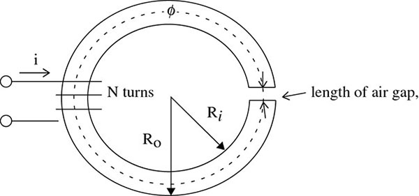
For Ampère's law, consider a toroidal non-ferromagnetic material, shown in Figure 3.1. Figure 3.1 Toroidal coil. Magnetic field is effectively confined to the volume within the toroid (cores). If Hr is the value of flux intensity at the average value path of radius r, it may be expressed as
or
The magnetic field is described by its magnetic flux density, denoted by a vector quantity
To analyze the concept of magnetic force:
where
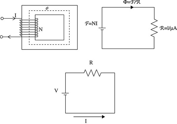
The constant of proportionality between The relation between the variables may be modeled by the equivalent magnetic circuit seen in Figure 3.2. Figure 3.2 Magnetic and electric circuit. The flux leakage λ of the toroidal core
So, using equivalent electric circuit
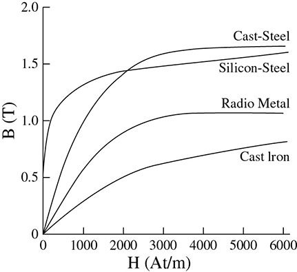
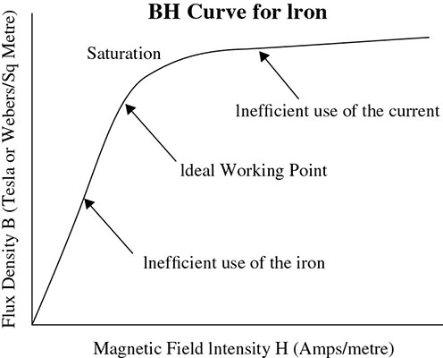
Examples of magnetic materials with high values of relative permeability μr are cobalt, aluminum, tungsten, and nickel. These are called ferromagnetic materials because they are relatively easy to magnetize. These ferromagnetic materials are classified as hard or soft materials. Soft materials include: soft steel, iron (Figure 3.3), nickel, cobalt, some rare-earth elements, and many alloys of elements. Hard ferromagnetic materials such as copper–nickel alloys and chromium–steel alloys are alloyed with aluminum, nickel, and cobalt. Figure 3.3 BH curve for some ferromagnetic materials. For ferromagnetic materials, the magnetizing curve shown in Figure 3.4 is not reversible; that is, if H is increased until the material is saturated, when H is reduced again the value of B does not reduce to zero along the same line. Figure 3.5 illustrates a hysteresis loop. Figure 3.4 BH curve for iron. Figure 3.5 A hysteresis loop for a solenoid's ferromagnetic core. In Figure 3.5 [11], the point 0, where the axes cross, represents a ferromagnetic material that is unmagnetized. As current in the coil increases, H also increases and between points 0 and 1, flux density, B increases following the magnetization curve. At point 1, the material has reached saturation and B no longer increases. To demagnetize the ferromagnetic material, we gradually reduce the current in the coil. As stated earlier, the graph will not follow the same path it did when the current increased; instead it goes from point 1 through point 2 then down to point 3. At point 2, H = 0, therefore the current has reached zero, but there is still some remnant flux density so that the material is still partially magnetized. The current is now reversed so that H is in the opposite direction as it was before; during this process, H has a negative value, therefore when the current is increased, the value of H reduces. At point 3, the material is finally demagnetized and the value of H at this point is called the coercive force. If the reversed current increases further, we reach point 4, where the material saturates so that the magnetic poles of the domains face in the opposite direction to those at point 1. The reversed current is now reduced and reaches zero at point 5; however, once again, some flux remains. If the current is now increased in the original direction, all the flux would have gone at point 6 and saturation is reached once more at point 1. Since the coercive force must be applied to overcome the remanent magnetism, work is done in completing the hysteresis loop and the energy concerned appears as heat in the magnetic material. This heat represents a form of energy loss known as hysteresis loss. The amount of loss depends on the material's value of coercive force. For example, by adding silicon to iron, a material with a very small coercive force can be made; such materials typically contain 5 percent silicon and have a very narrow hysteresis loop. Materials with narrow hysteresis loops are easily magnetized and demagnetized, and known as soft magnetic materials. Hysteresis loss is always a problem in AC transformers where the current is constantly changing direction. The magnetic poles in the core cause losses because they constantly reverse direction. Rotating coils in DC machines also incur hysteresis losses. Magnetic materials are subject to time-varying flux, which normally leads to energy loss in the material in the form of magnetic losses. Such magnetic losses are called iron or core losses. There is no core loss if flux does not vary with time. Core losses are defined as the sum of hysteresis and eddy-current losses, given by
where Ke = proportionate constant depending on the core materials, f = supply frequency, and Kn = property dependency on the magnetic material. According to Charles Steinmetz, hysteresis loss caused by energy needed to cause the reversal in the hysteresis loop is determined empirically as
where V is the volume of ferromagnetic material, f is the frequency (Hz), Kn is the property called dependency on the magnetic material. Kn for soft, 1 mm, silicon, sheet steel are 0.025, 0.001, 0.0001, respectively. Bm is maximum flux density and n is the Steinmetz exponent, which it varies from 1.5 to 2.5 or (2.0). Because iron is a conductor, time-varying magnetic fluxes induce opposite voltage and currents called eddy currents, which circulate within the core. The undesirable circulating current flow around the flux core is so large that it can demagnetize the magnets. Thus, eddy currents establish flux that opposes the original change imposed by the core. The equation for the eddy-currents loss calculation is
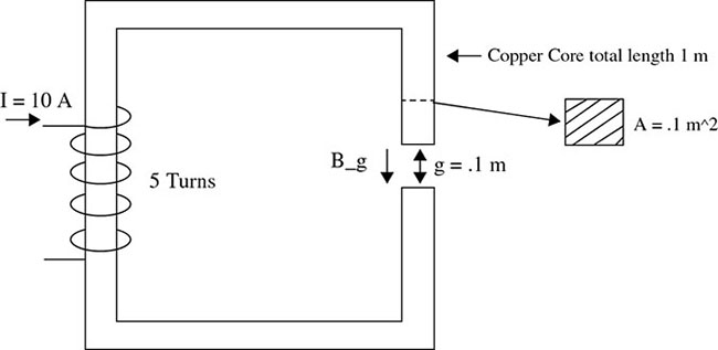
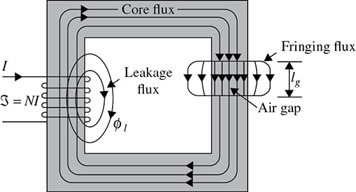
where Ke is the proportionate constant depending upon the core materials, V is the volume of ferromagnetic material (m3), ti is the lamination thickness, and Bm is the maximum flux density (T). I2R losses are found in windings of the machine. By convention, these losses are computed on the basis of the DC resistance of the winding at 75°C. I2R losses depend on the effective resistance of the winding under the operating frequency and flux conditions. Mechanical losses consist of brush and bearing friction and windage losses caused by running a machine at high speed while unloaded and unexcited. Frequently these losses are lumped with core losses and determined at the same time. Stray losses arise from nonuniform current distribution in the copper winding. There is no formula for its calculation. The usual approach is to take 1 percent of the output of the DC machine. For synchronous and induction machines, we can find it through testing. In general, the total losses contribute to determining a machine's efficiency, and this is used to compare different electromagnetic-based machines. The contribution of these losses for generators, motors, and transformers is usually determined to calculate their efficiency. In practice, not all the magnetic flux produced in a magnetic circuit will be concentrated within the core. Apart from the leakage flux, which will appear in the surrounding free space, if a gap exists within the magnetic circuit, the flux tends to spread out, as shown in Figure 3.6 [11]; this effect is known as fringing. Figure 3.6 Magnetic flux leakage and fringing. The production of magnetic flux is confined to a curved magnetic path in a toroid, as seen in Figure 3.7 [6]. The creation of flux in an air gap is also necessary for electrifying. Figure 3.7 Toroid with air gap. With an iron gap
If φ is the flux in the core of the toroid,
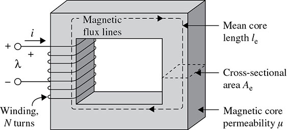
Let us consider a simple magnetic circuit, as shown in Figure 3.8 [12], with a single core material having uniform cross-sectional area A and mean length of flux path l. Reluctance offered to the flow of flux is ℜ. The corresponding electrical representation is rather simple. The equivalent electrical circuit is also drawn beside the magnetic circuit, as shown in Figure 3.9 for comparison. Figure 3.8 Rectangular magnetic circuit. Figure 3.9 Simple series magnetic circuit and analogous electric circuit. Although in the actual magnetic circuit, there is no physical connection of the winding and the core, in the magnetic-circuit representation, magnetomotive force (mmf) and reluctance are shown to be connected.
where Let permanence of the magnetic circuit
therefore
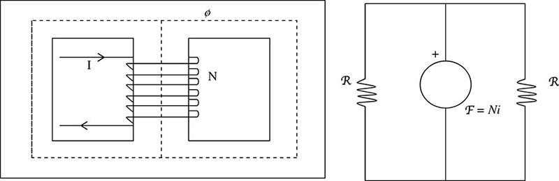
R can be connected in series or parallel (Figure 3.10) so that the equivalent reluctance is ℜeq. Figure 3.10 Parallel magnetic circuit. For a system of n series reluctances,
For reluctances in parallel
or permanence
if
and λ = Nφ
If
but
therefore
The inductance L is defined as the flux linkage per ampere of current flow in the coil. It is measured in henrys (H). Solution: F = BILsin θ Solution: Solution: The expression for induced voltage can be written as:
Solution: The expression for reluctance can be written as:
(a) increase, (b) remain the same, (c) decrease, or (d) become zero. Solution: The air gap will not change the exciting current. So, the exciting current remains the same. This is because the air gap is introduced to solve the problem of excessive flux produced by the high level of current. Solution: Hysteresis is loss due to the heating of the core as a result of the material molecular structure reverse, which occurs as the magnetic flux alternates.
Solution: Eddy-current loss is due to continuous induced current in the core. It results in excessive heating of the core. It can be minimized by using a core material of high resistivity or by using a thin sheet of lamination for the core.
Solution: The conditions for a magnetic field to produce voltage on a wire is that the conductor must be at an angle with the magnetic field, i.e.,
Solution: Ampere's law states that the line integral of the magnetic field intensity (H) around a closed path is equal to the total current enclosed by the path.
For a conductor in circular form
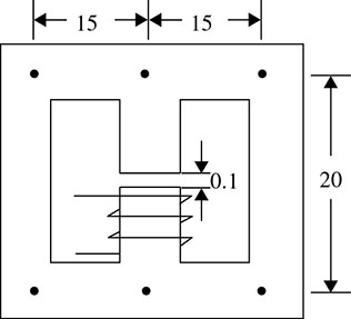
Lenz's law states that the direction-induced emf in the coil is such that it tends to oppose the motion of the flux producing it. The magnetic effect of electric current and its applications were the central objectives of this chapter. The centrality of Maxwell's equations to the development of various electromagnetic devices cannot be overemphasized. Working examples and applications of Maxwell's equations to a power energy system were provided. This is important because from generation through transmission down to distribution, critical components of the system are built and operated to provide quality and reliable power based on the principle of magnetic effect of electric current. This fundamental knowledge is essential to students who want to understand next-generation electric power systems as many of the components for power generation, protection, measurement, regulation, and security in a smart/microgrid environment are based on this essential principle. It is therefore essential foundational knowledge the student must embrace. The concepts described in this chapter are used in modeling electromechanical energy processing systems and components. Calculate the self-inductance L of a toroid with a square cross-section with inner radius a, outer radius b = a + h, (height h), and N square windings. 2mWb is to be produced in the air gap of the magnetic circuit shown in Figure Q3. How many ampere-turns must the coil provide to achieve this? Relative permeability μr of the core material may be assumed to be constant and equal to 5,000. All the dimensions shown are in cm and the sectional area is 25cm2 throughout. Figure Q3 Magnetic Circuit. The core loss in an iron-core reactor is 600 W, of which 400 W is hysteresis loss when the applied voltage is 220 V and the frequency is 60 Hz. Neglecting winding resistance:3.1 INTRODUCTION
3.2 MAGNETIC FIELDS
![]()
![]()
![]()
![]()
![]() (enclosed flux φ).
(enclosed flux φ).![]()
![]()
![]()
![]()
![]()
![]()
![]()
![]()

![]()
![]()
![]() . For different non-ferrous material, B is related to the magnetic field intensity H by the constant μ0 given by μ0 = 4π × 10− 7H/m
. For different non-ferrous material, B is related to the magnetic field intensity H by the constant μ0 given by μ0 = 4π × 10− 7H/m
![]()
![]()
![]()
3.3 EQUIVALENT MAGNETIC AND ELECTRIC CIRCUITS
![]()
![]()
![]()
![]() and φ is related by reluctance ℜ, given by
and φ is related by reluctance ℜ, given by
![]()

![]()
![]()
![]()
![]()
![]()
![]()
![]()
3.3.1 Differences between Magnetic and Electric Circuits
3.4 OVERVIEW OF MAGNETIC MATERIALS
3.5 HYSTERESIS LOOPS AND HYSTERESIS LOSSES IN FERROMAGNETIC MATERIALS

3.5.1 Hysteresis Loss
3.6 DEFINITIONS
3.7 MAGNETIC CIRCUIT LOSSES
![]()
![]()
![]()
3.8 PRODUCING MAGNETIC FLUX IN AIR GAP
![]()
![]()
![]()
![]() are the reluctances of the core and the air gap, respectively then
are the reluctances of the core and the air gap, respectively then
![]()
![]()
3.9 RECTANGULAR-SHAPED MAGNETIC CIRCUITS
![]()
![]()
![]()
![]()
![]()
![]()
![]() and
and ![]() , NI is mmf in ampere-turns, φ is flux in weber, and ℜ is reluctance.
, NI is mmf in ampere-turns, φ is flux in weber, and ℜ is reluctance.![]()
![]()
![]()
![]()
![]()
![]()
![]()
![]()
![]()
![]()
Illustrative Problems and Examples
![]()
![]()
![]()
![]()
![]()
![]()
3.10 CHAPTER SUMMARY
EXERCISES
BIBLIOGRAPHY