
CHAPTER 14
MICROGRID OPERATIONAL MANAGEMENT
A microgrid is a low-voltage distribution network consisting of different energy components such as wind, solar, storage system, diesel generators known as distributed energy resources (DERs), and controllable loads. With these components, a microgrid can either be connected to the grid or can be used in islanded mode (use DERs to supply the loads). Integrating DERs and controllable loads within the distribution network introduces unique challenges to microgrid management and control, which are implemented by an energy management system (EMS). Figure 14.1 shows the EMS structure for microgrid operation. Figure 14.1 Performance structure of a microgrid EMS. Forecasting is a process that uses past and present data for making predictions of future DERs, loads, and the market. Due to intermittency and variability of these factors, forecasting has become a challenging task for the power utilities. Therefore, accuracy of the forecast is crucial for the EMS to balance equality constraints, i.e., supply and demand in the microgrid. Various forecast methods are available in the literature: State estimation is a key function in building adequate network models for online monitoring and analyses. State estimation in a distribution system is becoming stringent because of the integration of DERs and the adoption of advanced technology for system modeling and operations for the distribution network. To manage large-scale DERs and load change, the operators in a distribution system need a robust distribution system state estimator (DSSE). The installation of supervisory control and data acquisition (SCADA) system at the feeder level and the widespread adoption of advanced metering infrastructure (AMI) have made the implementation of a reliable DSSE feasible. Various methods are utilized to solve DSSE issues, including: Load-flow studies play an important role in power system analysis and design. They give the steady-state solution of a power system network for normal operating conditions, helping in continuous monitoring of the current state of the system, and are employed for planning, optimization, and stability studies. All distribution of electrical energy is done by a constant-voltage system. In practice, the following distribution circuits are generally used: radial system, ring main system (mesh system), and interconnected system. Distribution networks are characterized by radial structure with high (Resistance to Reactance Ratio) R/X ratio feeders. A mesh network (having some loops) can be found in some modern distribution systems. A mesh network may be used to improve the system voltage profile, balance the load, and increase the supply reliability and efficiency. Thus, there is an increasing demand for a generalized load-flow method for distribution systems having more than one feeding source with a mesh-configured network. An efficient and fast load flow method is required. Load flow for a distribution system is divided into two categories: Real-time simulation refers to a simulation or computer model of a physical system that can execute at the same rate as actual “wall clock” time. For example: Various tools are available to work on real-time distribution systems, such as: For a deeper understanding, the reader can refer to papers on forecasting [18], state estimation [19], load flow [20], and real-time simulation of the microgrid [22]. Power quality has become a critical concern for utility customers. Power companies must improve service delivery to retain customers in the deregulated market. For this reason, distribution automation systems (DASs) have been implemented as an intelligent way to improve the reliability and operational efficiency of distribution systems. DASs are defined by the IEEE as systems that enable an electric utility to coordinate, monitor, and operate distribution network components in real time from remote-control centers. Given that information exchange between the DAS server and field equipment is critical for system operation, a reliable communication network constitutes the core of cutting-edge DAS applications. An essential feature of a microgrid with advanced smart distribution, unlike a traditional distribution network, is support for a large number of DAS function. Modeling and scheduling control problems in DG sources need to be resolved by DASs in the micro grid. Among the functions achieved by a DAS, fault detection, isolation, and restoration (FDIR) is considered most important. DAS functions also cover the following areas: Control options for a microgrid are as follows: Voltage control within an identified range of limits and capacitor switching is an effective method of improving voltage profiles, minimizing loss, and delaying construction of new generation within power quality and reliability constraints. In electric power systems, volt-ampere reactive (var) is used to express reactive power in a power system. Reactive power exists in an AC circuit when the voltage and current are not in phase. Voltage/var control considers a multiphase, unbalanced power distribution system operation, DG, and automated control equipment in large electric systems. Power system distribution automation functions use voltage/var control options to maintain proper parameters throughout the grid based on the requirements of different customers by employing variable capacitors. The improved control and management of voltage/var facilitates increase performance for customer equipment and allow both the consumer and the utility company to realize financial benefits. To improve efficiency, voltage/var is integrated with the load-management problem under four different objectives, as follows: Min.
where OC is the outage cost, Ykn is the level of curtailable load selection of type k at bus n (pu MW), Cmaxkn is the maximum curtailable MW of type k at the nth bus (pu MW), and CCkn is the curtailment cost of customer type k ($/pu MW). Min.
where Pnm, Qnm is the transfer power (branch n–m at pu) and Vn is the voltage of bus n (pu). Min.
Z = Min.
These objectives are subjected to different system constraints, such as:
where
Branch flow considers the recursive relationships between the successive nodes in the radial-distribution system. The demand in P, Q has an interruptible component, which is the load-management control option Y. In addition, the reactive power equation has the capacity-switching option Qs. Voltage limits/current limits:
Capacitor control limits:
Curtailable load-control limits:
Load frequency control (LFC) is of importance in microgrid system design and operation. The objective of LFC in an interconnected power system is to maintain the frequency of each area within limits and to keep tie-line power flows within some prespecified tolerances by adjusting the megawatt (MW) outputs of the generators to accommodate fluctuating load demands. A well-designed and well-operated power system must cope with changes in the load and with system disturbances, and should provide an acceptably high level of power quality while maintaining both voltage and frequency within tolerance limits. As power load demand varies randomly for an interconnected power system, both area frequency and tie-line power interchange varies also. The primary objective of LFC is to minimize transient deviations in area frequency and tie-line power interchange while ensuring that steady-state errors are as close to zero as possible. Frequency will not change in an interconnected network if there is a balance between customer demand and power supply resources that can also compensate for electrical losses. The operating point of the power system shifts from its scheduled operating point due to mismatch in generation and demand in the system. This is because without increase in mechanical input, sudden changes in demand in the system will be supplied from the stored kinetic energy of the rotating mass. This results a reduction in kinetic energy of the system, which will further cause the turbine speed reduction of the system. The speed is directly proportional to the frequency, hence frequency will also fail. The incremental power in the generation and demand is expressed in the system as a change in kinetic energy, increased load consumption, and increased power transferred in the interconnected system. This relation between the incremental power and system dynamics is given as follows. The stored energy in a generator rotor at the rated frequency and sensitive load dependency in frequency is
The incremental power is related to kinetic energy and frequency-dependent loads as shown:
Taking the Laplace transform of Equation 14.14,
where, ΔPm and ΔPL are the changes in mechanical power and load, Δf is the frequency deviation, H is the inertia constant, D is the load-damping coefficient, KP is the power system gain given by KP = 1/D, and TP is the power system time constant The aim is to minimize frequency deviation (ΔF) due to mismatch between generation and load. Power quality (PQ) is the capability of a power system to operate without causing disturbance or damage to components and loads. PQ is a significant concern because of the sensitivity of modern digital control equipment to PQ distortion and deterioration. A rudimentary requirement for maintaining PQ is balancing demand and supply. Characteristic metrics utilized as indictors of PQ measures include: A few accepted PQ standards apply to electrical power distribution systems. The European Norm 50160 standard outlines voltage disturbance standard requirements for acceptable PQ standards. Studies on PQ consider factors such as: Practically speaking, electrical power cannot be easily stored on a large scale. Thus, supply and demand must remain in balance in real time. Traditionally, utility companies have leveraged peaking power plants to increase power generation when needed to meet demand. Demand response, however, works from the opposite side of the equation: instead of adding more generation to the system, it pays energy users to reduce their consumption. Utilities pay for demand-response capacity because it is proven to be more flexible and less expensive than bringing additional generation online. Demand response offers an opportunity for consumers to play a substantial role in the operation of the microgrid by decreasing or shifting their electricity use during peak periods in response to time-based rates or other financial incentives. Demand-response programs are being utilized by electric system planners and operators as resource options for balancing supply and demand. These programs aid in lowering the cost of electricity in wholesale markets, which in turn leads to lower retail rates. Techniques of engaging customers in demand-response efforts include offering time-based rates such as critical peak pricing, variable peak pricing, time-of-use pricing, critical peak rebates, and real-time pricing. Other techniques include direct load-control programs that provide the ability for power utility companies to cycle loads that are noncritical, such as water heaters and air conditioners, on and off during periods of peak demand in return for a financial incentive and lower electricity bills. Demand-response programs are becoming an increasingly valuable resource option whose capabilities and potential impacts are expanded by modern microgrids. Microgrids have numerous sensors that can distinguish peak load problems and utilize automatic switching to divert or decrease power in strategic places, which removes the chance of overload and a resulting power failure. Advanced metering infrastructure increases the range of time-based rate programs that may be offered to consumers and smart customer systems such as in-home displays or home-area-networks that make it easier for consumers to change their electricity consumption patterns and reduce peak-period consumption based on information on their power consumption and costs. These programs also possess the potential to assist electricity providers in saving money through reductions in system peak demand, and the ability to defer addition or construction of new DG plants and power-delivery systems—particularly those reserved for use during peak times. Demand-side management (DSM) is a set of interconnected and flexible programs that allow customers a bigger role in shifting their own demand for electricity during peak periods, reducing their energy consumption overall. DSM program consists of two principal activities: demand response programs or “load shifting,” and energy efficiency and conservation. The evolution of microgrid technology will permit customers to make informed decisions about their energy consumption, regulating both its timing and quantity. Key levers of successful DSM initiatives include incentives, rates, technology, access to information, controls, public education, and marketing, along with verification and customer insight. Each lever has a distinct influence on customer behavior and depends on the circumstances of the particular utility, such as customer base and geography. Certain combinations of actions within and across levels may produce greater results. In an emergency, a microgrid is frequently required to reconfigure itself as soon as possible in order to support continuous electricity supply to essential loads. Types of operations, including topology switching, generation regulation, and load shedding, are concerned with reconfiguration. Therefore, the problem of reconfiguration turns out to be a typical constrained, nonlinear optimization problem with discrete, Boolean and continuous variables, which is usually too complex to be solved by regular optimization methods. Reconfiguration is a category of emergency control, which includes topology changes with load-generation control measures that play an essential role in helping microgrids switch from integration mode to island mode. Dissimilar from large systems, topology reconfiguration is deemed as the final line of defense, only taken into consideration when there is an extreme emergency state to avoid uncontrollable blackout of the entire system—while it is a frequently used control method in microgrids. In an emergency, the microgrid is expected to be operated as an island to protect itself from being infected by faults in the main system. By applying flexible electrical/electronic interfaces, both microgrid and energy storage systems can switch on/off seamlessly and realize “plug and play” functionality. Generally, a microgrid can operate in both the grid-connected mode and the islanded mode, where the microgrid interfaces with the main power system by a fast semiconductor switch called a static switch (SS). It is critical to protect a microgrid in both the grid-connected and the islanded modes of operation against all types of faults. The major problem arises in island operation with inverter-based sources. Inverter fault currents are limited by the ratings of the silicon devices to around two per unit rated current. Fault currents in islanded inverter-based microgrids may not have sufficient magnitudes to use traditional over-current protection systems. This possibility requires an extended protection strategy. The philosophy for protection is to have the same protection strategies for both islanded and grid-connected operation. The SS is designed to open for all faults. With the SS open, faults within the microgrid must be cleared with techniques that do not rely on high-fault currents. The fault analysis of a power system is required in order to provide information for the setting of relays, selection of switchgear, and stability of system operation. Several types of fault analysis are carried out using software packages and data collected from the microgrid system. Faulty-analysis types include symmetrical and asymmetrical, short circuit, stability, and transient. Microgrid is a concept where local energy sources in remote areas, both in renewable (such as PV, small wind generator, etc.) and nonconventional (fuel cells, microturbine, and diesel generator) resources, are tapped and interconnected to form a low-voltage utility system. These small DGs all have different owners, and the supply loads locally with the help of local controllers (µc). A µC controller takes decisions such as scheduling of generation as per load forecast (i.e., unit commitment) and economic dispatch of connection with each DG and microgrid central controller (µcc). In the islanding operation of a microgrid, each source caters to only those loads stipulated for the source. However, when these sources are connected with the microgrid, which is most desirable, the action of the controllers should have a certain degree of intelligence for participation in a common and competitive market. The role of the EMS in the microgrid scenario is for making decisions with regard to the best use of the generator for producing heat and electricity, i.e., CHP operation. Such decisions are based upon the heat requirements of the local establishments, climate, cost of fuel, price of electric power, and many other variables. The market price is the lowest price obtained at the point of intersection of the aggregated supply and demand curves. At this price both suppliers of generation and customers are satisfied and enough electricity will be supplied from accepted sales bids to satisfy all the accepted purchase bids. The costs incurred in the production of electricity are solely dependent on the type of technologies and fuel used for electricity production. The DG units that use natural gas (microturbines) or diesel have higher marginal costs and these plants are called the price setting units, while mini-hydro plants have a low marginal cost. Electricity cannot be stored as long as there are no electricity alternatives for consumers to react to the price signal. These two points lead to an inelastic demand curve. In the case of renewable sources, the current cost of buying energy is relatively low, with no fuel or operational costs involved compared to the capital cost of buying a wind turbine or PV module. Economic analyses in these cases are performed using a simple payback period. CO2 emissions are absent and the resulting no-carbon incentives are an added advantage. Since electricity can be produced in many ways using a variety of fuels and applying different technologies, different cost structures apply, with important implications for price formation on short-term electricity markets. This standard defines synchronized phasor measurements used in power system applications. It provides a method to quantify the measurement, tests to be sure the measurement conforms to the definition, and error limits for the test. It also defines a data communication protocol, including message formats for communicating this data in a real-time system. This standard focuses on the technical specifications for, and testing of, the interconnection itself. It provides requirements relevant to the performance, operation, testing, safety considerations, and maintenance of the interconnection. It includes general requirements, response to abnormal conditions, PQ, islanding, and test specifications and requirements for design, production, installation evaluation, commissioning, and periodic tests. The stated requirements are universally needed for interconnection of distributed resources (DR), including synchronous machines, induction machines, and power inverters/converters, and will be sufficient for most installations. The criteria and requirements are applicable to all DR technologies with aggregate capacity of 10MVA or less at the point of common coupling, interconnected to electric power systems at typical primary and/or secondary distribution voltages. Installation of DR on radial primary and secondary distribution systems is the main emphasis of this standard, although installation of DR on primary and secondary network distribution systems is also considered. This standard is written considering that the DR is a 60 Hz source. The IEC 61970 series of standards deals with the application program interfaces for EMS. The series provides a set of guidelines and standards to facilitate: High-speed peer-to-peer IEC 61850-8-1 (International Electrotechnical Commission (IEC) 61850-8-1) generic-object-oriented substation event (GOOSE) and IEC 61850-9-2 sampled values (SVs)–based information exchange among IEDs in modern IEC 61850 substations have opened the opportunity for designing and developing innovative all-digital protection applications. The transmission reliability and real-time performance of SVs and GOOSE messages, over the process-bus network, are critical to realize all-digital IEC 61850 substation automation systems (SASs) protection applications. To address the reliability, availability, and deterministic delay performance needs of SASs, a novel IEC 61850-9-2 process-bus based substation communication network (SCN) architecture is proposed in this standard. This standard provides the utility industry and vendors with a set of security requirements for advanced metering infrastructure (AMI) to be used in the procurement process, and represents a superset of requirements gathered from current cross-industry-accepted security standards and best practice guidance documents. This standard defines a table structure for utility application data to be passed between an end device and a computer. The end device is typically an electricity meter, and the computer is typically a handheld device carried by a meter reader, or a meter communication module that is part of an automatic meter-reading system. C12.19 does not define end-device design criteria or specify the language or protocol used to transport that data. There are however related ANSI standards that do specify the transportation of these tables. ANSI C12.18 describes the communication of C12.19 tables over an optical port. ANSI C12.21 describes the communication of C12.19 tables over a modem. ANSI C12.22 describes the communication of C12.19 tables over a network. Many microgrid projects have been developed with government or research funding, and many are in various stages of planning and development. Reasons for this interest in microgrids primarily revolve around a number of benefits that the microgrid can provide to stakeholders that go beyond energy provision alone. These may include a variety of technical and social benefits. Due to the comparatively high cost of renewable and small thermal generation, energy storage systems, and other equipment necessary to develop a microgrid, microgrids may not be cost-competitive on the basis of energy price alone, but a host of benefits may result from the various operational advantages of the DR units on which the microgrid is based (e.g., efficiency, low emissions, and close proximity to loads) and microgrid functionality (e.g., ability to island and various “smart grid” functionalities such as demand response and SCADA). Some of these benefits are valued as services by the market or contract in a few jurisdictions. The division of benefits depends on the ownership model and the regulatory and market environment, and so before undertaking an analysis of benefits of the microgrid, it is critical to understand the ownership model and the goals of the microgrid developer. In general, the microgrid can be owned by the DNO or utility, the customer, or an IPP. In each case, benefits will be valued differently. DNOs would tend to value technical benefits such as reduced peak loading, whereas the customer would likely value energy-cost reduction. A free-market IPP-owned model, on the other hand, could be operated with the interests of all stakeholders in mind, insofar as they are represented by financial incentives. It has been suggested that with the proper incentives in place, profit maximization for an IPP could automatically optimize the benefits for other stakeholders. The revenue-requirements model is the most rigorous methodology for electric utility cost–benefit analysis. This technique represents the complete financial environment of a utility, accounting for taxes, depreciation, and time/value costs of money, actual capital investment, and operation and maintenance expenses. Two or more alternatives, each of which may involve differing life cycles and cash flows, can be compared on a common basis. With the revenue-requirement methodology, several alternatives are defined, and the cash flows for capital investment and operation and maintenance expenses are determined. Problem 1 Problem 2 At approximately 8:50 a.m. Saturday morning, PEPCO reports a service interruption affecting approximately 17,000 customers in northwest Washington, DC, including the main campus of Howard University. Service is restored at approximately 11:30 a.m. to all buildings on the main campus. Such outages can cause Howard University a loss of $400,000 per annum at an initial rate of 5 percent. To prevent further outages, the university is looking into a microgrid alternative on a five-year project plan. The various costs incurred and estimates and the derived benefits are summarized in Table Q2 TABLE Q2 Summary of Estimated Cost and Derived Benefits Problem 3 Discuss the control options for the proposed Howard University microgrid in Problem 2 to combat voltage/var, frequency variation and PQ problems. Problem 4 The following are utilized for real-time data measurement in a microgrid system: power management units, smart meters, DSSE. Provide a: Problem 5 Use a simple optimization process to construct the algorithm for load-flow implementation. Write the power-flow equations in terms of rectangular coordinates. For example, express complex voltage at bus n as
Problem 6 Discuss the importance of the demand response and demand-side management in distribution automation. Problem 7 Discuss different techniques for forecasting. Selecting any one of the techniques, perform the forecasting for DERs or on-load demand. Problem 8 What is PQ disturbance and what are its causes? It is envisioned that the microgrid will integrate renewable energy sources, particularly solar and wind, with conventional power plants, in an intelligent and coordinated way by utilizing energy-conversion technologies. It is expected that energy conversion devices will allow for improved reliability, dependability, and service continuity while also effectively reducing energy consumption and considerably reducing carbon emissions. All these requirements dictate the modernization of the power grid by installing intelligent electronic and conversion devices such as sensors, switches, power electronic converters and inverters, and advanced communication for data acquisition and interactive software for real-time control that optimizes the operation of the entire electrical system and makes more efficient use of the grid assets. This chapter detailed the technology and tools needed for design of microgrid systems in support of future network designs.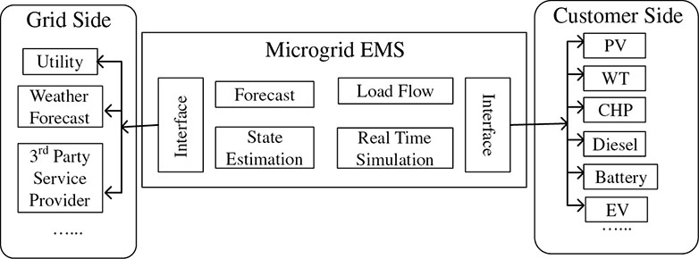
14.1 PERFOMANCE TOOLS OF A MICROGRID
(a) Forecasting
(b) State Estimation
![]()
(c) Load Flow
(d) Real-Time Simulation
14.2 MICROGRID FUNCTIONS
14.2.1 Control Options for Microgrid Technology
Voltage/var Control
![]()

![]()
![]()
Branch-flow equation
![]()
![]()
![]()
![]()
![]()
![]()
![]()
Load Frequency Control
![]()
![]()
![]()

![]()
![]() .
.Power Quality
14.2.2 Demand Response
14.2.3 Demand-Side Management
14.2.4 Reconfiguration
14.2.5 Fault Analysis
14.2.6 Energy Pricing
14.3 IEEE STANDARDS FOR MICROGRIDS
14.3.1 IEEE Standards for Synchro Phasors for Power Systems (IEEE C37.118, 2005)
14.3.2 IEEE Standard for Interconnecting Distributed Resources with the Electric Power System (IEEE 1547, 2003)
14.3.3 Common Information Model for Power Systems (IEC 61968/61970)
14.3.4 Communication Networks and Systems in Substations (IEC 61850, Ed. 1, 2009)
14.3.5 Advanced Metering Infrastructure System Security Requirements (AMI–SEC, June 2009)
14.3.6 American National Standards Institute (ANSI) End-Device Data Tables (ANSI C12.19, 2008)
14.4 MICROGRID BENEFITS
14.4.1 Cost–Benefit Analysis in Microgrids
14.4.2 Cost–Benefit Analysis Methodology
14.4.3 Illustrative Problems and Examples
Quantity
Average Value (in millions of dollars)
*Capital investment (one-time cost)
3.000
*Installation (one-time cost)
0.800
Maintenance and operations
0.007
Reduction in losses
0.035
![]()
14.5 Chapter Summary
BIBLIOGRAPHY