
CHAPTER 16
SMART-GRID LAYERS AND CONTROL
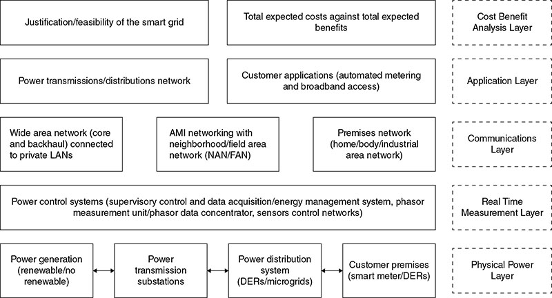
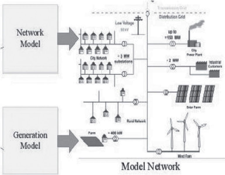
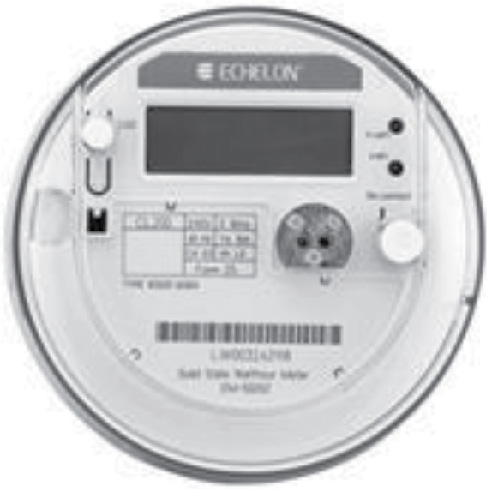
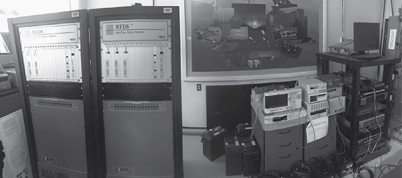
This chapter aims to evaluate various control systems involved in a smart grid. The layers of a smart grid, including the physical, real-time measurement, communication, application, and cost–benefit analysis will be comprehensively reviewed. State-of-the-art tools for control and communications are evaluated, as are related issues and challenges. Smart grid as a case study of a cyber-physical system will also be described. Smart-grid control is important so that the following can be achieved: A key element of smart-grid operation is the grid energy management system (EMS). It includes control functions that define the grid as a system that can manage itself, operate autonomously or grid connected, and seamlessly connect to and disconnect from the main distribution grid for the exchange of power and the supply of ancillary services. Hierarchical levels of control for micro grids may be categorized as primary, secondary, and tertiary, Figure 16.1. Primary control is the level in the control hierarchy that is based exclusively on local measurements, which includes islanding detection, output control, and power sharing (and balance control). Secondary control, the energy management system (EMS), is responsible for microgrid operation in either the grid-connected or islanded mode. Tertiary control is the highest level of control and sets long-term and “optimal” set points depending on the host grid's requirements. Figure 16.1 Hierarchical levels of control in microgrid. Voltage/frequency control enables prevention of reductions in the power factor or efficiency of a motor in a wide range of variable speed operations for changes in the frequency for speed control by outputting a voltage (V/f characteristic) corresponding to the frequency set by a parameter in an inverter. The revolution speed of an induction motor is proportional to the frequency, which can reduce the power factor and efficiency of a motor even with a variable frequency because changes to the frequency cause the internal impedance of a motor to change. Therefore, you must change the voltage corresponding to the frequency. V/f control reduces the torque in low-speed operation with the primary resistance voltage drop even though it attempts to keep the torque stable regardless of the frequency. Fault protection involves monitoring the microgrid system, identifying when a fault has occurred, pinpointing the type of fault and its location and setting into motion-control schemes for recovery from the fault. The major protection problem in microgrid is a result of a large difference between fault currents in the grid-connected and islanded modes. An optimal smart-grid protection system must be very sensitive to faults and be able to selectively sectionalize the microgrid, especially in the case of renewable-energy resources with power electronic interfaces (low-fault-current levels). A decision must be made by the integrated device control whether to sectionalize/isolate the microgrid or to shut it down entirely. This decision, in the event of a fault, is dependent on the needs of the customers and on cost benefits. Cost benefits in this case imply whether the cost involved in protection and communication could be justified for benefits gained by sectionalizing the microgrid instead of shutting it down entirely. The benefit in sectionalizing the microgrid involves reducing the end-consumer service interruption time. Droop control enhances the power-quality parameters, like active and reactive power controls both in grid and autonomous operation. Droop-control techniques have been employed in voltage (V) and current (I) to provide power-quality control in the microgrid. Droop control is designed for batteries and generators to coordinate the sources and regulate the system frequency. Peer-to-peer strategy implies that every distributed source maintains the same status in the microgrid. The benefit is that extra sources can be integrated into the microgrid without modifications to the control and protection of units that are already part of the system. This implies that every controller must be able to respond effectually to system changes without requiring data from other sources or locations, resulting in an improvement in the reliability of the smart grid and reducing system cost. Peer-to-peer strategies can be realized by droop control. There are two control methods based on droop control: Master–slave strategy refers to the presence of a master controller in the smart grid while others are slave controllers that obey the rules of the master controller through a communication link. When in a grid-connected mode, the microgrid requires no frequency regulation because the traditional grid can stabilize the system frequency. However, when islanded from the main grid, the master controller takes up the task of maintaining system frequency, voltage, and power balance separately by V/f control and regulating its own output. Resynchronization control: While connected to the grid, micro sources can maintain a high level of output and high efficiency. In islanded mode, the master micro source switches from power-quality control to V/f control to provide frequency and voltage support to the microgrid, while other micro sources are still power-quality controlled. The regulation of this control strategy can only involve micro sources’ output power, but not the transfer power between the microgrid and the traditional grid. Seamless transfer control is an important control technology to affect a smooth transition of the microgrid between islanded and grid-connected modes. This smooth transition is done by controlled triggering of antiparallel thyristor (SCR) considering bulk grid state, microgrid operation mode and direction of power flow. The supervisory control system is the master control of a microgrid. It organizes and schedules the midterm and long-term energy flow in the power system, and aims to achieve an optimal operation of the system as a whole. It manages the dispatching and control of all the active components of a microgrid. Supervisory control may be regarded as a piece of intelligence-embedded software, a computer algorithm, or similar that aims to achieve optimal system operations. These operations depend on a set of goals, rules, and constraints, which are to be defined before the system is developed. According to the International Energy Agency, following supervisory control goals is of primary importance. Effective supervisory control should consider economics, reliability and service delivery factors discussed below. Operation control strategies generally incorporate multiple objectives in their design. The smart grid is a virtual concept and there are just a few working smart grids in the world. But before it becomes a more widespread reality, a model needs to be developed that can mimic its behavior, issues, challenges, and operation in real time. This model should take into consideration all characteristics of the smart grid and must be inclusive of all the mathematical relations that exist—from simple line parameters to state estimation and power management units. One such model under review is Smart Grid Maturity Model (SGMM), a management tool that helps utilities plan smart-grid implementation, prioritize options, and measure progress. Conceptual models for the smart grid map out generation, transmission, and distribution, plus markets, operations, service providers, and consumption. Each of these domains has its own terms, some reflecting a century of use, with others invented daily. For instance, the acronym HEMS (home energy management systems) did not exist until a few years ago, but now is commonly used in the dynamic business sector focused on software and hardware for consumption solutions and services. Other emerging industries, like renewables and energy storage, are also producing new words and acronyms. So there is a need for a unique model that is inclusive of both longtime and emerging standards and norms for the sake of simplicity and easy understanding. A performance index for the smart grid also needs to be calculated and distributed. Different researchers and industry experts calculate performance measures differently; no unique terms exist that can universally state smart-grid performance. The following functions in the operation of a smart-grid system can be controlled: Frequency control uses load frequency control methods to control for regulation of load, i.e., transfer of load, load shedding, and utilization of available storage options, including the connection of distributed generation (DG) if available. Hence, by regulating the load at the point, the frequency can be controlled. Voltage control uses var compensators, switching of load, capacitors, new transformers, new substations, and new lines. Real-time voltage stability indices (VSI) may also be calculated using optimal power flow (OPF) or advanced measuring devices like PMUs. VSI provide stability limits for the system, which enables the determination of system instability. Protection control can be achieved by implementing microprocessor relays, circuit breakers, sectionalizers, and other devices. The operation of these protection devices is coordinated by a SCADA and EMS for improved dynamic protection. Stability control is achieved by monitoring and maintaining system performance indices, which provide measures of system stability such as a reliability index, angle stability index, VSI, or vulnerability indices. Supervisory control and data acquisition (SCADA) is a computerized system used for collecting data and controlling one or more remote stations from a master control station. It is comprised of sensing and digital control equipment, telemetry equipment, and two-way communications channels between the centralized master and remotely controlled stations. SCADA digital control equipment includes computers and terminals for data entry and display. Telemetry and sensing equipment includes sensors, analog-to-digital (ADC) and digital-to-analog (DAC) relays, actuators, and converters used at remote stations to sense normal operating and alarm conditions as well as to activate equipment remotely. Communications equipment includes modems for transmitting data and a communications link (power line, phone line, radio-microwave link). Typical functions performed by the SCADA include: With the modern automation of substation functions, a SCADA system can perform the following functions remotely at a substation: Load control and demand response: Both the customer side and the supply side of the meter are mutually significant when considering energy efficiency (EE), demand response (DR), and load control (LC) implications of the smart grid. Variations in the types of loads are also a critical consideration. The vital load types that impact EE, DR, and LC of the smart grid comprise industrial, commercial and residential loads. The smart grid has commenced exploration into real-time pricing, demand bidding, DR, and other consumer-response programs. The market for these programs is currently fragmented, and there is a lack of a clear vision and developed policy to guide the implementation of technology, which blurs the direction that the smart grid will take. While regulators are supportive of the promotion of energy efficiency, the impact of technologies and applications for future development are not fully understood. Substation controllers: In the future, remote terminal units will provide system protection, local operation, graphical user interfaces, and data gathering/concentration from other systems. This will be in addition to customary station telemetry functions and control to the master station. The substation controllers will provide functionalities such as: Distributed energy resources (DER) comprise DG and energy storage devices that can help increase grid reliability and help manage peak loads. Sufficient DER allows a utility company to defer capital investments in the generation, distribution, and generation layers in addition to lowering emissions and improving system security. However, some are not yet cost competitive when compared with traditional sources of generation, and need more sophisticated integration strategies as penetration rates rise and a new pricing model for electricity. The smart grid is the incorporation of communication infrastructures into the electrical grid to enhance the information exchange and achieve fully automated management in power systems. From this point of view, smart-grid architecture is divided into five dominant layers: Physical layer, Real-time measurement layer, Communications layer, Application layer and Cost–benefit layer. This system architecture for the smart-grid paradigm is detailed in Figure 16.2. Figure 16.2 Smart-grid layers. There are various energy options in powering a smart grid that are consistent with powering any grid, that are part of the Physical Layer on Figure 16.3. Figure 16.3 Physical layers. Real-time measurements, monitoring, and control are the specialty of the smart grid, and involve the latest communication and real-time devices to make control operations faster and facilitate the grid with self-healing and self-restoration qualities. Core duties are evaluating congestion and grid stability, monitoring equipment health, energy theft prevention, and control strategies support. Technologies include: advanced microprocessor meters (smart meters) and meter-reading equipment, wide-area monitoring systems, dynamic line ratings (typically based on online readings by distributed temperature sensing combined with real-time thermal rating (RTTR) systems), electromagnetic signature measurement/analysis, time-of-use and real-time pricing tools, advanced switches and cables, backscatter radio technology, and digital protective relays. The following are details of some of these real-time measurement layer tools: (a) Smart Meters A smart meter, shown in Figure 16.4 [1], is an electronic device that records consumption of power in intermissions of an hour or less and communicates that information at least daily back to the utility for monitoring and billing. Figure 16.4 Smart meter. Automated meter reading (AMR)—the replacement of conventional, mechanical meters read once a month with smart meters that can be remotely read every ten minutes or so—is often the starting point for smart grid implementation. AMR, and its two-way enhancement advanced metering infrastructure (AMI), is often the costliest component of a smart grid because of the hundreds of thousands of meter end-points. In some parts of the world, there has been a tendency to consider an AMR/AMI system and its communications requirements as an independent solution rather than as part of the entire smart-grid infrastructure. (b) Phasor Measurement Units High-speed sensors called phasor measurement units (PMUs) distributed throughout a network can be used to monitor power quality and in some cases respond automatically. Synchronized PMUs (synchro-phasors) provide real-time measurement of electrical quantities from across a power system. Applications of synchro-phasor measurements include validating system models, determining stability margins, maximizing stable system loading, islanding detection, systemwide disturbance recording, and visualization of dynamic system response. The basic system building blocks are GPS satellite-synchronized clocks, a phasor data concentrator (PDC), and visualization software. Figure 16.5 [2] shows a sample phasor measurement unit. Figure 16.5 Phasor measurement unit. The accuracy, speed, and reliability of PMUs are critical to fulfilling the promise of the smart grid. However, the current standard that governs PMU performance is quite broad, and testing by the National Institute of Standards and Technology has shown that PMUs from various manufacturers can report dynamic conditions very differently. For example, the primary transducer that converts high line voltages to smaller voltages used by the measuring system can introduce inaccuracies. From the primary transducer, signals pass through an anti-aliasing filter that also generates some level of error. Next, the signal goes through an analog/digital (A/D) converter that can introduce magnitude or gain errors and channel phase shifts. Signal processing is carried out to evaluate the phasor magnitude and phase angle, which may create additional error; the phase is reported with respect to the global time reference so errors in the global positioning system (GPS) source and cable delays may introduce synchronization errors. The goal of PMU calibration is to ensure that all PMUs have consistent performance across the system, are interoperable regardless of their makes and models, and comply with system application requirements. A general rule of thumb is that a calibration system should have less than one-fourth of the total uncertainties of the system under calibration. (c) Geographical Information Systems Spatial data systems, including geographical information systems (GISs), have been used successfully by utility companies, government agencies, and many industries for more than three decades. Systems based on spatial technology have had a positive impact on a wide variety of business processes, ranging from marketing to environmental management. Spatial systems bring geography into play within the business processes of a company or organization while enabling data to be visualized more effectively. Smart-grid analytical software such as distribution management systems (DMSs) and outage management systems require high-quality data to provide the right answers. By using the functionality inherent in GIS, smart-grid technology will start with better-quality data and should, in turn, produce better-quality analytics and operational decisions. (d) Remote Terminal Units A remote terminal unit (RTU) is a microprocessor-controlled electronic device that interfaces objects in the physical world to a distributed control system or SCADA by transmitting telemetry data to the system, and by using messages from the supervisory system to control connected objects. The primary source of real-time data in a smart grid is the remote terminal unit (RTU). While most utilities have long had RTU technology in almost every transmission substation, these devices have historically been far less common in distribution substations. (e) Analog to Digital/Digital to Analog Superior in quality, reliability, and performance, analog devices’ energy-metering ICs combine analog-to-digital converters (ADCs) with fixed-function digital signal processors (DSPs) to perform critical measurements while providing unparalleled functionality and ease of use in energy metering. The need for more efficient utility substations and smart-grid management is growing as worldwide electricity demand increases. Electric utility companies need power-line monitoring systems to monitor and control energy consumption, cost, and quality, as well as to protect expensive equipment from power surges and severe storms. The new simultaneous-sampling ADCs provide the resolution and performance needed for next-generation power-line monitoring system designs that ensure the reliable delivery of electricity to millions of people in all corners of the world. Real-time measurable quantities include The communications layer has premises networks, neighborhood/field-area networks (NAN/FAN), and wide-area networks (WAN). The premises network, such as the home-area network (HAN), building-area network (BAN), and industrial-area network (IAN), provides access to applications in customer premises. The NAN/FAN provides a relatively long-distance communication link between smart meters, field devices, DERs, customer premises’ networks, and WAN. The WAN provides very long-distance communication links between the grid and the utility via a core network and FAN/NAN. However, the coverage area and data-rate requirements for the customer premises’ network, FAN/NAN, and WAN vary for different communication standards and protocols. Network security is an important consideration for any smart-grid deployment. Integrating communications technologies and control functionalities to traditionally isolated grid equipment raises apprehensions among utilities, regulators, and consumers. Distributed automation necessitates additional security procedures, as these protection and control functions alter how distribution networks are configured, and eventually the behavior of the electricity that is delivered to the customer. Guaranteeing the integrity of messages to and from distributed control equipment is paramount to detecting and reacting to incomplete and tampered communication signals. Just as with AMI, encryption, authentication, authorization, and accounting are important in order to limit access and the ability to compromise the network. The grid of the future will rely extensively on communication technologies for critical functionalities such as protection, monitoring, and control of electrical equipment. Hence the security of such a connected structure from any cyberattack is of paramount importance. Security against any physical attack is also a concern. In the event of a security breach, it is expected that the grid will detect and isolate such a breach to minimize its effect while raising an alarm to prompt service restoration. (a) Wide-Area Networks Wide-area networks (WANS) form the communication backbone for connecting the highly distributed smaller area networks that serve power systems at various locations. If control centers are located far from substations or end consumers, real-time measurements taken at the electric devices are transported to the control centers via WANs and, in the reverse direction, WANs perform the instructions communicated from control centers to the electric devices. (b) Field-Area Networks Field-area networks (FAN) create the communication facilities for electricity distribution systems. Electrical sensors on transformers and distribution feeders, IED devices capable of carrying out control commands from DMS, DERs in the distribution systems, plug-in electric vehicle (PEV) charging stations, and smart meters at customer premises form the key sources of information to be monitored and controlled by the DMS at the control centers. Power system applications operating in the distribution domain exploit FANs in order to exchange and share information. (c) Home-Area Networks Home-area networks (HANs) are essential in the customer domain to perform control and monitoring of smart devices inside customer premises, and to employ new functionalities such as DR and AMI. Within customer premises, a secure two-way communication energy services interface (ESI), acts between the customer and utility. The ESI supports several types of interfaces, including the utility-secured interactive interface used to secure two-way communications and the utility public-broadcast interface that allows one-way receipt of price and event signals located at customer devices. (d) Power-Line Communication Power lines are primarily used for electrical power transmissions; however, they can also be used to transmit data. Power-line communication (PLC) systems function by sending modulated carrier signals over power transmission cables. Normally, data signals cannot propagate through transformers, so the PLC signal is restricted to line segments between transformers. (e) Wireline Networks Dedicated wireline cables can be used to create data-communication networks that are independent of electrical power lines. Those these dedicated communication networks require additional investment for cable deployment and installation, they offer greater communication capacity and reduced communication delays. Subject to the transmission medium used, wireline networks may include Ethernet, SONET/SDH, coaxial cable access networks, and DSL. SONET/SDH networks transmit high-speed data packets using optical fiber cables with supported data rates between 155 Mbps and 160 Gbps. (f) Wireless Networks Innovation in wireless networking technology has enabled the connection of devices wirelessly, eliminating the need to install physical wires or cables. Generally, wireless signals are subject to transmission attenuation as well as environmental interference. The result is that wireless networks usually provide short-distance connections with relatively low data rates. The 802.11 networks are the most popularly used for local-area wireless networks, communicating at a maximum data rate of 150 Mbps and a maximum distance of 250 m. The Open Systems Interconnection (OSI) model conceptually characterizes and standardizes the communication functions of a telecommunications or computing system without regard to their underlying internal structure and technology. Its objective is the interoperability of diverse communication systems through standard protocols. The model partitions a communication system into several abstraction layers. The original model defined seven layers: The smart grid features widespread interconnections of power equipment to enable two-way flows of electricity and information for various intelligent power-management applications, such as accurate relay protection and timely DR. To fulfill such pervasive equipment interconnects, a full-fledged communications infrastructure is of great importance in the smart grid. There has been extensive work on different layouts of communication infrastructures in the smart grid by surveying feasible wired or wireless communication technologies, such as power-line communications and cellular networks. A variety of smart-grid applications demand robust communications capabilities that span across a wide range of often-conflicting requirements. Proper networking protocols can provide strong support to help mitigate many of the challenges associated with AMI and DA applications. These protocols can incorporate standards, help perform preliminary processing, help monitor and optimize network reliability, and incorporate varying security features for different applications. By using standards-based communications protocols, the flexibility and longevity of the network can be enhanced. Utility communications should be compliant with TCP/IP and UDP/IP to allow the utility to make use of the widest variety of standards, including IEEE 61850 and distributed network protocol (DNP), whether IPv4 or IPv6. Compliance with IP will also ease developers’ concerns regarding the creation of new applications and process modeling. Providing an internet protocol (IP)-based solution also eases concerns about multi-vendor network interoperability for electric utilities. Various standards have been recommended to guide the development of smart-grid power systems. These standards cover several technical features of the power systems, including power equipment, electricity services, management automations, and system control and protection. Standards that can be used to guide the development of communication systems are as follows: (a) Distributed Network Protocol The distributed network protocol (DNP) went through many revisions to before the current version (DNP3). The DNP3 standard sets the protocols used for substation automation through LAN and WAN. It is utilized when implementing substation SCADA control systems. Devices compatible with the DNP3 protocols exchange control and status information to automate substation management. DNP3 uses the IP suite to transport packets. Hence, it adopts a layered architecture with all the DNP3 packets encapsulated into TCP or UDP packets throughout the transmission. Security controls are provided by virtual private network (VPN) and IPsec, which are derivatives of the IP suite. DNP3 is used in substations for equipment monitoring and control. It uses the basic functions of an automated system to communicate equipment states to the control station and convey configuration commands to electric equipment. (b) IEEE Standards IEEE has recommended several standards associated with communications in power systems, such as C37.1, 1379, 1547, and 1646. (c) IEC Standards The International Electro-Technical Commission (IEC) has recommended a number of standards for the communication and control of microgrid electric power systems. Standard 60870 outlines the communication system used for power-system control. Through the standard, electric equipment is able to interoperate to achieve automated management. This standard comprises six parts, which specify the general requirements for power-system performance and interoperability. Standard 61850 focuses on substation-automated control. It states comprehensive communication functions and system-management requirements to facilitate substation management. The management perspectives include system reliability, availability, security, maintainability, integrity, and general environmental conditions. Standards 61968 and 61970 provide common information models for data exchange between networks and devices in the power-distribution and power-transmission domains, respectively. Cybersecurity of the IEC protocols is addressed by standard 62351, which stipulates the requirements for achieving different security objectives, including data confidentiality, data authentication, intrusion detection, and access control. (d) NIST Standards The National Institute of Standards and Technology (NIST) has published standards that provide guidance to the construction of smart grids. The NIST Special Publication 1108 designates a road map for the standards on smart-grid interoperability. It states the vision and importance of the smart grid, explains the conceptual reference model, classifies implementation standards, recommends priority action plans, and stipulates security assessment procedures. Specifically, it presents the expected services and functions in the smart grid and the application and requirements of communication networks in the operation of a smart grid. NIST report 7628 focuses on information-security issues of the smart grid. It gives details on the critical security challenges of the smart grid, presents security architectures, and stipulates security requirements. Security objectives and strategies are mentioned, including cryptography, privacy, key management, and vulnerability analysis. Report 7628 seeks to ensure reliable and trustable communications for automated energy management in the smart grid. Some communications are up-to-date but are nonuniform because they have been developed in an incremental fashion and not fully integrated. In most cases, data is being collected via modem rather than direct network connection. Areas for improvement include: substation automation, DR, distribution automation, SCADA, energy-management systems, wireless mesh networks, power-line carrier communications, and fiber optics. Integrated communications will allow for real-time control, information, and data exchange to optimize system reliability, asset utilization, and security. Smart-grid concepts encompass a wide range of technologies and applications. We describe a few below that are currently in practice with the caveat that, at this early stage in the development of smart grids, the role of control, especially advanced control, is limited. The following are application functions of a smart-grid: Cost–benefit analysis (CBA) is a systematic approach to estimating the strengths and weaknesses of alternatives and is used to determine options that provide the best approach to achieve benefits while preserving savings. If all the equipment that needs to be installed for communication and control operation are considered, the CBA for the smart grid can be calculated by considering costs for such items as PMUs, smart meters, relative communication infrastructure, relative protection systems, and RTUs, and comparing them to the benefits obtained through installation of these devices. Worst-case analysis should also be carried out to have a better idea of CBA, e.g., consider that after installing everything if grid performance does not change much then benefits obtained will be minimal. Physical benefits can also be converted into societal benefits or utility economic benefits. CBA should be carried out with different contingencies applied. Considering the economic potential of the smart grid and the requisite considerable investments, it is important to estimate the costs and benefits of control and communication of smart grids. There are four major guidelines for performing a comprehensive CBA: (a) Definition of Assumption and Setting of Critical Parameters This involves definition of boundary conditions (demand growth forecast, discount rates, local grid characteristics) and of implementation choices (roll-out time, chosen controls, communication functionalities). Furthermore, for CBA studies input information such as critical data related to the project, social discount rate and project value in terms of weight of importance is required. (b) Steps of Classical CBA The assessment framework is expressed by the following seven steps based on the approach developed by the Electric Power Research Institute (EPRI). The benefit of charting assets to functionalities and functionalities to benefits is that they assist in thinking of sources of benefits, making a complete set of estimated benefits more likely. Evaluation of the impact of a project is made easy. Progress measurement, toward attaining characteristics of the comprehensive smart grid control is facilitated. Progress is measured through some previously established standard key performance indicators such as enhanced efficiency and better service in electricity supply and grid operation, and voltage quality performance of electricity grids (e.g., voltage dips, voltage and frequency deviations). The relationship between assets and benefits through functionalities is more than likely not to be easily deduced and requires a good deal of brainstorming. However, execution of these steps adds clarity to a CBA process. Step 1: Review and define project goals. This step involves summarizing and describing the elements and goals of the project. The goals must be concise and clearly defined. This may involve collation of the following information: Step 2: Define and map assets to functionalities. Determining which smart-grid functionalities are activated by the control assets proposed by the project is an important early step in a CBA for smart-grid projects. Smart-grid assets provide different types of functionalities that enable benefits. If the assets deployed and/or functionalities enabled by the project are unclear, the analysis is likely to be incomplete. Step 3: Map functionalities to benefits. Each functionality should be considered individually and assessed on how it could contribute to any of the benefits. This analysis should be thorough and applied to all applicable functionalities. Step 4: Define the baseline. This involves the formal definition of the “control state” that reflects the smart-grid condition that would have occurred had the project not taken place. This is the baseline condition against which all other setups are compared. The CBA is based on the variance between the costs and benefits associated with the “do-nothing” scenario and those associated with the implementation of the project. These two scenarios are: Step 5: Monetize the benefits. In this step, data required to quantify the benefits in equivalent monetary forms are gathered. The data may be already analyzed or may be in its raw form. The benefits to be calculated and the baseline scenarios needed to calculate those benefits determine the type of data collected. Each set baseline and established benefit requires compilation of data for computation. Data should be collected both before and after implementation of the control and communication project. Conceptually, the monetary value of a benefit can be calculated as: For example, the estimate of the benefit reduction in meter-reading costs could be done by comparing the total cost of local meter readings for an established baseline that do not have smart meters installed (i.e., the “do-nothing” scenario) to the cost of local meter readings under project conditions for the fraction of customers who use smart meters (communication scenario). Next, the benefits quantified are expressed in equivalent economic terms and benefits are allocated to different beneficiaries, like consumers, retailers/aggregators, and society at large. A concluding step would be to carefully assess any uncertainty. This is because it may not be possible to provide a good estimation of some control and communication benefits—for instance those based on environmental or socioeconomic factors—with the same level of precision and clarity as other benefits. Step 6: Quantify cost. The costs of a project are incurred in implementing the project, relative to the predefined baseline scenario. This step involves evaluation of the cost-benefits of the project and the advantage is that it facilitates calculation of a project's return on investment (ROI). Step 7: Compare costs and benefits. Once costs and benefits have been estimated, there are several methods to compare them to evaluate the cost-effectiveness of the project. (c) Sensitivity Analysis Sensitivity analysis is performed to determine the range of variables that would result in a positive outcome of a CBA. It requires identifying the value that would have to occur for the NPV of the project to become zero, or more generally for the outcome of the project to fall below the minimum level of acceptability. (d) Evaluation of Merit and Social Impact A qualitative-impact analysis is performed to evaluate the social impacts, typically representing a significant portion of the project externalities. These include: The costs and benefits of smart-grid systems include both tangible and intangible benefits. The companies have estimated costs and benefits for individual smart-grid programs and DR through their respective project applications. With DR, the projected benefits by far exceed the estimated program costs, primarily due to capacity deferral. With AMI, the tangible quantifiable benefits are comparable to the costs; however, not all tangible benefits can be quantified. Across the nation, there are many examples of business case analyses that were developed for utility smart-grid projects, as well as by organizations such as the EPRI, the Edison Electric Institute (EEI), the Utilities Telecom Council (UTC), and numerous consultants. In many of these cases, utility smart-grid projects show net benefits. Analysis of the costs and benefits of these business cases will help increase understanding of all the benefits and costs of smart-grid projects and better inform our business case development. That said, it is essential to develop business cases for each smart-grid project or integrated set of projects specific to each system and customer base. Developing accurate assumptions before having specific data is difficult. Data from the companies’ pilots, demonstrations, and targeted deployment projects will help validate some of the benefits derived from implementing a smart grid. Smart-grid goals include implementing targeted deployments focused on increasing the ability to accommodate increased levels of renewable energy, and on improving the efficient utilization of electricity (energy efficiency) all the way to customer end uses, while ensuring grid reliability and service quality are maintained or improved. The pace of smart-grid implementation will depend on the business case for each smart-grid application, availability of commercially viable solutions, and availability of resources across utility companies. Smart grid is the term generally used to describe integration of the elements connected to the electrical grid with an information infrastructure to offer numerous benefits for both the providers and consumers of electricity. It is an intelligent future electricity system that connects all supply, grid, and demand elements through an intelligent communication system. The backbone of a successful smart-grid operation is a reliable, resilient, secure, and manageable standards-based, open communication infrastructure that provides for intelligent linkages between the elements of the grid while participating in the decision-making that delivers value to the utility and supply-and-demand entities connected to it. The general purpose of a smart grid is to monitor electricity consumption and to manage its delivery to avoid blackouts or brownouts. RER integration and other advanced real-time communication devices have added complexity into the system and posed many questions, such as: The above questions must be answered by researchers in related fields, industry experts, and standards organizations before advancing the grid. In addition, certain technical areas concentrating in controls should be evaluated, such as: A grid that is considered “smart” uses information technology in the operation of the transmission grid as much as it does in the distribution network. The lifeblood of any smart-grid network is inherently the data and information that drive the applications that, in turn, enable new and improved operational strategies to be deployed. Data collected at any level of the system, from customer metering to distribution, transmission, generation, and market operations, may be pertinent to improving operations at any other level. Thus, sharing data in a timely fashion, approaching real-time, with all those with a need or right to know, is an essential ingredient of a smart grid. The smart grid involves many real-time devices: PMUs, smart meters, SCADA, DMS, EMS, and many more including real-time sensors and power electronics devices. These all work together to achieve smart-grid objectives. A smart grid should have self-healing and self-restoration qualities and should monitor at each single corner of the system for abnormalities in order to self-heal or self-restore. So, it needs to check voltage, current, phase angle, and frequency at each node of the grid. It also should compare the obtained quantities with the overvoltage and overcurrent quantities at that node. If abnormalities are found, the control action should be initiated immediately and automatically. For global control, PMU can help to measure voltage and phase angle for wide areas. For local control, CTs and PTs, various meters, and transducers connected at each level can help to initiate relays, circuit breaker, or any other protective device operation. Moreover, smart grids will be inclusive of stochastic behavior due to RER and randomly changing loads. So, to carry out control operation in this environment requires continual dynamic optimal power flow calculations. This can be achieved with the help of next-generation optimization tools such as adaptive dynamic programming (ADP), stochastic programming (SP), mixed-integer programming (MIP), evolutionary programming (EP), or heuristic programming. Security measures involve addition of the latest devices into the system such as PMUs, which can measure quantities of voltage and phase angle for a large area and compare quantities of one area with another to help catch abnormalities immediately. They also allow monitoring through graphs, signals, and charts, making monitoring easy and convenient. Other optimization tools to can calculate optimal power flow to enhance the system with the ideal conditions and easily locate abnormal values at each end so they can be corrected before becoming an issue of major concern. While managing a system with RER, we should include advanced storage options such as supercapacitors, hydrogen storage, hydro storage, and flywheels so that, in case of fault, these sources can help compensate for shortcomings in power needs. Contingency analysis is an important part of control system design and deserves extra effort. Contingency analysis gives the extreme values (max, min) for line parameters that a system can withstand. Also, through contingency analysis one can rank such values to see whether one or more abnormalities are going on in parallel and which should be attended to first. Power systems are fundamentally dependent on control, communications, and computation for ensuring stable, reliable, efficient operations. Generators rely on governors and automatic voltage regulators (AVRs) to counter the effects of disturbances that continually buffet power systems, and many would quickly lose synchronism without the damping provided by power system stabilizers (PSSs). FACTS devices, such as static var compensators (SVCs) and HVDC schemes rely on feedback control to enhance system stability. At a higher level, EMSs use SCADA to collect data from expansive power systems and sophisticated analysis tools to establish secure, economic operating conditions. Automatic generation control (AGC) is a distributed, closed-loop control scheme of continental proportions that optimally reschedules generator power set points to maintain frequency and tie-line flows at their specified values. The use of time-synchronized, high-data-rate sensor technology is widely viewed as a critical enabler for increasing the reliability of the power grid while allowing the integration of many more stochastically variable renewable-energy sources such as solar radiation and wind. PMUs are capable of sampling frequency, voltage, and current thousands of times per second and outputting accurate, time-stamped measurements 30–120 or more times per second. It is difficult, however, for utilities to take full advantage of these devices due to a lack of tools for designing and evaluating the control systems that exploit them. Furthermore, the behavior of such control systems also depends on the performance of the wide-area communications systems that connect the sensors, control logic, and actuators, and whose design and specifications are themselves still evolving. The smart grid will consist of intelligent devices that use advanced communication methods, which in turn will improve situational awareness and enable networked control. Networked control will increase efficiency, reliability, and safety; enable plug-and-play asset integration, such as in the case of DG and alternative energy sources; support market dynamics; and reduce peak prices and stabilize costs when supply is limited. Networked smart devices currently include smart meters at the customer site and PMUs (including synchro-phasors) in the transmission and distribution grids. In the future, smart appliances will adjust their functions depending on instantaneous electricity costs, and a host of communicating devices will enable the feedback-loop networked control of the smart grid. Smart-grid communication should protect users’ privacy and security. Networked control requires adequate, real-time performance and reliability. Communication should use existing infrastructure whenever possible, due to: Smart-grid devices can communicate over a variety of substrates with different properties. Furthermore, different media may be appropriate in different circumstances. For example, smart appliances in the home can exploit existing Ethernet home LANs, 802.1I home wireless LANs, or power line home networks. At the other end, if a synchro-phasor is deployed in the transmission grid, it may be better served by wide-area wireless, such as a mesh network or a power-line wide-area network. Since the smart grid will exploit different types of data from a variety of devices communicating over heterogeneous networks, communication should be possible across various media, which in turn requires a convergence layer, such as the IP. Figure 16.6 shows the Howard University microgrid test bed with OPAL-RT, which uses the very latest technology—an advantage to the power-system engineer as speed, flexibility, and creativity is encouraged and enhanced. The introduction of the OPAL-RT real-time digital simulator to the array of research and educational equipment at the Center for Energy System and Control (CESaC) at Howard University through the US Department of Energy has added capacity for improvement in research and educational output. Figure 16.6 Howard University microgrid test bed with OPAL-RT. Cyber-physical systems (CPS) are the next generation engineered system with tools such as communication, control and computation working together. By definition, CPS is a mechanism that is controlled by computer-based algorithms, closely integrated with the internet and its users. the terms in CPS are defined as follows: Cyber-Physical is then deeply embedded computing and communication platform. Practical applications of CPS include manufacturing environment, healthcare environment, transportation environment, renewable energy environment, smart grids and others. Where it provides a system with new capabilities, reduced cost of building and operating system and provide safer and efficient system. In smart grids and microgrids, the CPS provides secured system against attacks by providing attack and counter attack schemes. These capabilities CPS will be realized by deeply embedding computational intelligence, communication, control, and new mechanisms for sensing, actuation, and adaptation into the physical system with active and reconfigurable components. The capabilities are added to the physical system as shown in Figure 16.7. For the design of CPs, a theoretical foundation will be created consisting of Figure 16.7 Convergence of computation, communication, information, and control. The system model and communication model have a real-time data from a test bed, consisting of renewable-energy sources, storage, meters, and PMUs that capture real voltages of the system. Research computes the system model from the signals, which are the voltage stability index, frequency control index, and power quality index. Communication network failures can be caused by a noisy environment, congestion, bandwidth problems, or link failures and have a two-way communication with an effective communication interface for effective control of power-quality problems, load-flow problems, and voltage/var problems. Figure 16.8 shows summary of Smart grid Attributes with cyber physical system. Figure 16.8 Smart grid with CPS attributes. The role of real-time metering, communication, command, and control in efficient running of smart grids was one objective of this chapter. Also, the layers of smart grids were comprehensively treated. Smart grids operate based on coordinated control of numerous functions, devices, and sensors to achieve the central goal of quality, reliable, available power. This is may be achieved through real-time assessment and utilization of results of real-time measurement and data gathering using smart communication devices and metering systems. An effective smart grid requires various functions—such as demand-side management, power-quality control, load-frequency control, voltage/var control, load reconfiguration, energy resources management, and monitoring and control of protective devices—to be carried out simultaneously and in real time.16.1 INTRODUCTION
16.2 CONTROLS FOR THE SMART GRID
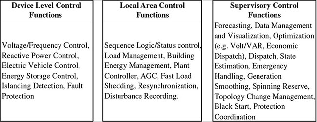
16.2.1 Device-Level Control
16.2.2 Local-Area Control
16.2.3 Supervisory Control Functions
16.2.4 Evaluation of Control Types Taking Area into Consideration
Development of Concepts, Models, and Performance Index
Controls for Operation of a Smart-Grid System
16.3 LAYERS OF SMART GRID WITHIN THE GRID
16.3.1 Physical Power Layer
16.3.2 Real-Time Measurement Layer

Real-Time Measurable Quantities
16.3.3 Communications Layer
Communication Networks
Communication Protocols and Standards
Integrated Communications
16.3.4 Application Layer
16.3.5 Cost–Benefit Layer
![]()

Value Proposition (Return on Investment) for Smart Grid
16.4 COMMAND, CONTROL, AND COMMUNICATION APPLICATIONS IN REAL TIME
16.4.1 Need for Command, Control, and Communication
Real-Time Measurable Quantities
Overvoltage Limits
Security Measures
Contingency Analysis
16.4.2 Application of Control and Communication to the Smart Grid in Real Time
16.5 HARDWARE-IN-THE-LOOP FOR ENERGY PROCESSING AND THE SMART GRID
16.6 CYBER-PHYSICAL SYSTEMS FOR SMART GRIDS


16.7 CHAPTER SUMMARY
BIBLIOGRAPHY