
Solar radiation
3.1 Guidance
3.1.1 What is solar radiation?
Of all the factors that control the weather, the sun is by far the most powerful, and practically everything that occurs on the Earth is controlled, directly or indirectly, by it. The sun affects the places humans inhabit, in the kind of homes that are built, the work that is done, and the equipment that is used.
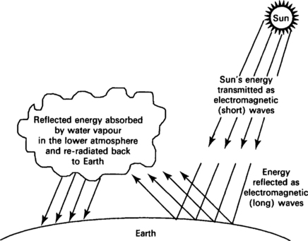
Less than one-millionth of the energy emitted from the sun’s surface travels the ninety-odd million miles to reach this planet. The sun’s energy crosses those miles in the form of short electromagnetic radio waves, identical in nature to those used in broadcasting, which pass through the atmosphere and are absorbed by the Earth’s surface. These waves warm the Earth’s surface and are then re-radiated back to space. The wavelength of the energy emitted by the Earth is very much longer than that emitted by the sun, because the Earth is much cooler than the sun. These longer waves are not able to pass through the atmosphere as freely as short waves. A large proportion of the energy emitted by the Earth is absorbed by the water vapour and water droplets in the lower atmosphere which in turn is re-radiated back to Earth. Thus the Earth plays the part of a receiving station absorbing short electromagnetic waves and converting them into longer electromagnetic waves, while the atmosphere acts as a trap containing most of the longer electromagnetic waves before they are lost to space.
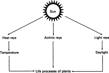
Radiation from the sun consists of rays of three differing wavelengths, heat rays, actinic rays and light rays. Heat rays and actinic rays are intercepted by solid bodies and produce peculiar effects in varying degrees according to the nature of the surface on which they fall. The light rays are responsible for daylight and both light rays and actinic rays are necessary for the life processes of plants. The heat ray’s most important manifestation is temperature. Although latitude determines the intensity of insolation this, together with the length of day, influences the duration of sunshine and therefore the temperature.
Radiant energy can be reflected from solid surfaces and intensified by that reflection. For example, reflection from walls is frequently used for ripening peaches and pears. Reflection from bare ground can also assist in the ripening of melons and other creeping plants, while reflection from water surfaces enhances the ‘climatic reputation’ of waterside resorts. However, radiant energy can also cause damage to equipment as heat rays can warm the material or its surrounding environment to dangerous levels and photochemical degradation of materials can be caused by the ultraviolet content of solar radiation.
3.1.2 Introduction
On cloudless nights when atmospheric radiation is very low, objects exposed to the night sky will attain surface temperatures below that of the surrounding air temperature. For example, a horizontal disc thermally insulated from the ground and exposed to the night sky during a clear night can attain a temperature of –14°C when the air temperature is 0°C and the relative humidity is close to 100%. The lowest possible values of atmospheric radiation during clear nights are shown in Figure 3.3. These values are of assistance when determining the ‘under temperature’ of components.

Fig. 3.3 Lowest values of atmospheric radiation during clear nights (reproduced from the equivalent standard BS 7527 Section 2.4;1991 by kind permission of the BSI)
The Sun’s electromagnetic radiation consists of a broad spectrum of light ranging from ultraviolet to near infrared. Owing to the distance of the sun from the Earth, solar radiation appears on the Earth’s surface as a parallel beam and the highest (maximum) level of radiation occurs at noon on a cloudless day at a surface perpendicular to the sun.
Most of the sun’s energy reaches the surface of the Earth in the 0.3–0.4 μm range and the density of the solar radiated power (or irradiance – expressed in watts per square metre) is dependent on the content of aerosol particles, ozone and water vapour in the air. The actual amount of irradiance will vary considerably with geographical latitude and type of climate (i.e. temperature, humidity, air velocity, etc.).
Having said that, an object subjected to solar radiation will obtain a temperature depending on the surrounding ambient air temperature, the intensity of radiation, the air velocity, the incidence angle of the radiation on the object, the duration of exposure, the thermal properties of the object itself (e.g. surface reflectance, size, shape, thermal conductance and specific heat) together with other factors such as wind and heat conduction to mountings and surface absorbency, etc.
3.1.2.1 Photochemical degradation of material
One of the biggest problems caused by solar radiation is the photochemical degradation of most organic materials which in turn causes the elasticity and plasticity of certain rubber compounds and plastic materials to be affected and can, in exceptional cases, make optical glass opaque.
Although solar radiation can bleach out colours in paints, textiles, paper, etc. (a major consideration when trying to read the colour coding of components), by far the most important effect is the heating of materials.
The combined effect of solar radiation, atmospheric gases, temperature and humidity changes, etc. are often termed ‘weathering’ and result in the ‘ageing’ and ultimate destruction of most organic materials, e.g. plastics, rubbers, paints, timber, etc.
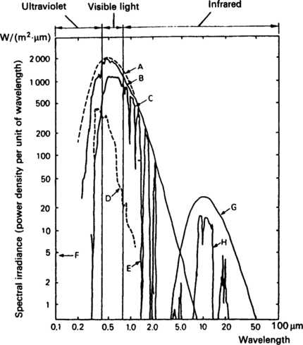
Fig. 3.4 Spectra of electromagnetic radiation from the sun and surface of the Earth (reproduced from the equivalent standard BS 7527 Section 2.4;1991 by kind permission of the BSI)
3.1.2.2 Effects of irradiance
To guard against the effects of irradiance, the following guidelines should be considered when locating electronic equipment:
• the sun should be allowed to shine only on the smallest possible casing surfaces;
• Windows should be avoided on the sunny side of rooms housing electronic equipment;
• heat sensitive equipment parts must be protected by heat shields made, for instance, of polished stainless steel or aluminium plate;
• air conditioning plant and cooling fans (when used) in rooms housing electronic equipment should be efficient and reliable;
• convection flow should sweep across the largest possible surfaces of materials with good conduction properties.
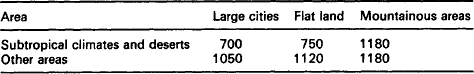
Table 3.1
Mean daily extraterrestrial global irradiation (kWh/m2)
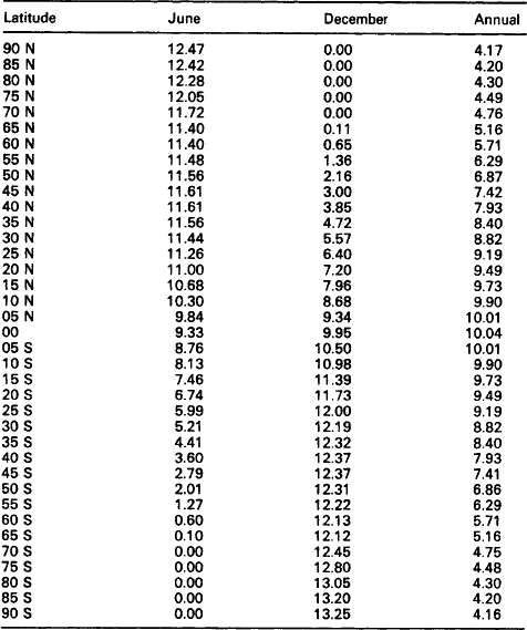
(reproduced from the equivalent standard BS 7527 Section 2.4; 1991 by kind permission of the BSI)
Figures 3.5 to 3.7 are world maps produced by the IEC/BSI and show levels of relative global irradiation for June, December and the global mean irradiance for the year. These values have been derived from satellite measurements and give an indication of the intensity of the sun’s rays.

Fig. 3.5 Mean relative global irradiation for the month of June (in percent) (reproduced from BS 7527; Section 2.4; 1991 by kind permission of BSI)
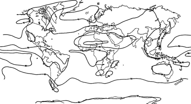
Fig. 3.6 Mean relative global irradiation for the month of December (in percent) (reproduced from BS 7527; Section 2.4; 1991 by kind permission of BSI)
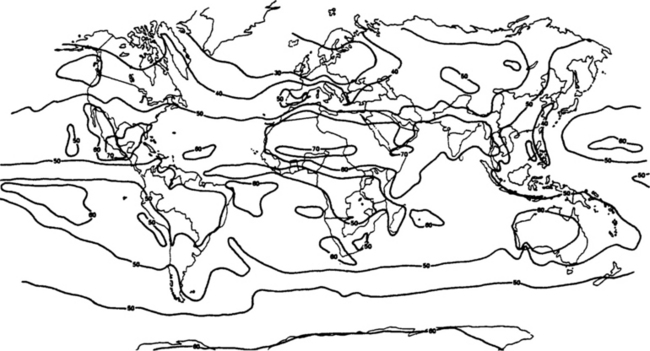
Fig. 3.7 Mean relative global irradiation for the year (in percent) (reproduced from BS 7527; Section 2.4; 1991 by kind permission of BSI)
3.1.2.3 Heating effects
As stated before, probably the most important effect of solar radiation heating is mainly caused by the short-term, high intensity radiation around noon on cloudless days. Typical peak values of irradiance are shown in Table 3.2.
Table 3.2
Typical peak values of irradiance in W/m2 from a cloudless sky
In December the monthly mean average of daily irradiation will reach approximately 10.8 kWh/m2 close to the South Pole, because of the duration of daylight. Outside of the Antarctic area, daily levels reach approximately 8.4 kWh/m2. The highest annual mean averages of daily global irradiation (up to 6.6 kWh/m2) are mainly found in desert areas.
As equipment (if fully exposed to solar radiation) in an ambient temperature such as 35–40°C can attain temperatures in excess of 60°C, one has to consider an equipment’s outside surface. To a major extent the surface reflectance of an object affects its temperature rise from solar heating and changing the finish from a dark colour to a gloss white can cause a considerable reduction in temperature. Conversely, a pristine finish that has been designed to reduce temperature, can be expected to deteriorate in time and result in an increase in temperature.
Another problem found in most of today’s materials is that they are also selective reflectors, i.e. their spectral reflectance factor changes with wavelength. For example, paints are, in general, poor infrared reflectors although they may be very efficient as a visible warning. Care should, therefore, be taken when selecting materials and finishes for equipment casings.
3.1.3 Test standards
The following is the most used specification for solar radiation:
| IEC 68.2.5 | Environmental testing procedures – Test Sa: Simulated solar radiation at ground level |
3.1.4 Other related standards and specifications
| EN 50125 | Railway applications-Environmental conditions for rolling stock equipment |
| G. Major et al. | World maps of relative global radiation. World Meteorological Organisation, Technical Note No. 172, Annex. WMO-No. 557, Geneva (1981). |
| IEC 68.2.9 | Environmental testing procedures – Guidance for solar radiation testing |
| IEC 721.2.4 | Classification of environmental conditions–Environmental conditions appearing in nature–Solar radiation and temperature |
| ISO 4892 | Methods of testing plastics – Optical and colour properties, weathering |
3.2 Typical contract requirements – solar radiation
More and more modern day contracts are stipulating adherence to environmental specifications. These specifications describe the various conditions that are likely to be experienced by equipment when in storage, transit or use. In addition, as equipment is likely to be exposed to great extremes of solar radiation because of their function (e.g. equipment housed in direct sunlight must be able to function equally well in the radiation from the sun as the shade of tunnels and buildings), it is important that manufacturers and suppliers are aware of the requirements from an equipment point of view.
It is usual, therefore, to find that the general requirements for installing electronic equipment include the following stipulations:
• the sun should be allowed to shine only on the smallest possible casing surfaces and the convection flow should sweep across the largest possible surfaces of materials with good conduction properties;
• windows should be avoided on the sunny side of rooms housing electronic equipment;
• air conditioning plant and cooling fans (when used) in rooms housing electronic equipment shall be efficient and reliable.
3.2.1.1 Severity of solar radiation
Normally the customer or end user will define the severity (i.e. the amount of) solar radiation to which products are liable to be exposed during transportation, storage and use in accordance with the values and ranges shown in Section 3.3.
3.2.1.2 Effects of solar radiation
The following are some of the requirements frequently found in contracts:
3.2.1.3 Production configuration
A normal contract requirement is that all proposed candidate equipment, components or other articles have to be tested in their production configuration without the use of any additional external devices that have been added expressly for the purpose of passing solar radiation testing.
3.2.1.4 Procuring specifications
Procuring specifications frequently require that when tested, the sample (component, equipment or other article) shall perform as stipulated in the procuring specification and over the designated range.
3.2.1.5 Test methods
When a contract requires a test to be performed to prove the equipment’s capability of withstanding solar radiation, the usual standard quoted is IEC 68.2.5 (see Test 3.4.1).
The type of instrument considered most suitable for monitoring irradiance is a ‘pyrometer’ which is used for measuring combined solar and sky radiation on a horizontal plane.
3.3 Values and ranges
Guidance on geographical values and ranges of solar radiation has been taken from the latest issue of the IEC 721 standard. These figures are based on observations over a period of not less than 10 years and represent conditions frequently met by products whilst being transported, stored, installed or used.
Except where stated, all values given represent the maximum and minimum solar radiation experienced by a particular piece of equipment in a particular location and situation.
Deviation from the solar radiation tables is normally subject to acceptance by demonstration that the equipment is suitable for service.
Table 3.3
| Installation location | IEC 721 class | Solar radiation W/m2 |
| Fully air conditioned enclosed locations, with air temperature and humidity control | 1K1 | 500 |
| Fully air conditioned, temperature controlled, enclosed locations without humidity control | 1K2 | 700 |
| Fully enclosed locations without air temperature or humidity control | 1K3 | 700 |
| Partially weather protected locations without air temperature or humidity control1 | 1K4 | 1120 |
| Partially weather protected locations without air temperature or humidity control1 | 1K5 | 1120 |
| Partially weather protected locations without air temperature or humidity control1 | 1K6 | 1120 |
| Restricted non-weather protected locations1 | 1K7 | 1120 |
| Moderate non-weather protected locations1 | 1K8 | 1120 |
| Worldwide non-weather protected locations1 | 1K9 | 1120 |
| Non-weather protected locations with tropical damp climates (rainforests) | 1K10 | 1120 |
| Non-weather protected locations with tropical dry climates (deserts) | 1K11 | 1120 |
1The choice of classification is dependent upon the type of climate in which the equipment will be installed.
Table 3.4
Solar radiation – transportation
| installation location | IEC 721 class | Solar radiation W/m2 |
| Weather protected heated and ventilated | 2K1 | 700 |
| Weather protected, ventilated but unheated in general climates excluding cold and cold temperate climates | 2K2 | 700 |
| Non-weather protected, unventilated and unheated in general climates excluding cold and cold temperate climates | 2K3 | 1120 |
| Non-weather protected, unventilated and unheated in general climates including cold and temperate climates | 2K4 | 1120 |
| Non-weather protected conditions worldwide | 2K5 | 1120 |
| Non-weather protected conditions excluding cold and cold temperate climates | 2K5H | 1120 |
| Non-weather protected conditions including cold temperate climates | 2K5L | 1120 |
| Non-weather protected conditions covering tropical damp climates (rainforests) | 2K6 | 1120 |
| Non-weather protected conditions covering tropical dry climates (deserts) | 2K7 | 1120 |
Table 3.5
| Installation location | IEC 721 class | Solar radiation W/m2 |
| Stationary use at weather protected, fully air conditioned locations with temperature and humidity control | 3K1 | 500 |
| Stationary use at weather protected, temperature controlled locations with partial humidity control | 3K2 | 700 |
| Stationary use at weather protected, temperature controlled locations with no humidity control | 3K3 | 700 |
| Stationary use at weather protected, temperature controlled locations with no humidity control | 3K4 | 700 |
| Stationary use at weather protected locations with no temperature control and a wide range of relative humidity | 3K5 | 700 |
| Stationary use at partially weather protected locations with no temperature or humidity control1 | 3K6 | 1120 |
| Stationary use at partially weather protected locations with no temperature or humidity control1 | 3K7 | 1120 |
| Stationary use at partially weather protected locations with no temperature or humidity control, not exposed to solar radiation | 3K7L | None |
| Stationary use at partially weather protected locations with no temperature or humidity control1 | 3K8 | 1120 |
| Stationary use at partially weather protected locations with no temperature or humidity control1 | 3K8H | 1120 |
| Stationary use at partially weather protected locations with no temperature or humidity control | 3K8L | 1120 |
| Stationary use at partially weather protected locations in tropical damp climates (rainforest) | 3K9 | 1120 |
| Stationary use at partially weather protected locations in tropical dry climates (desert) | 3K10 | 1120 |
| Stationary use at restricted non-weather protected locations1 | 4K1 | 1120 |
| Stationary use at moderate non-weather protected locations1 | 4K2 | 1120 |
| Stationary use at general non-weather protected locations1 | 4K3 | 1120 |
| Stationary use at worldwide non-weather protected locations1 | 4K4 | 1120 |
| Stationary use at worldwide non-weather protected locations, low air temperature, low absolute humidity1 | 4K4H | 1120 |
| Stationary use at worldwide non-weather protected locations, high air temperature, low relative humidity, high absolute humidity1 | 4K4L | 1120 |
| Stationary use at non-weather protected locations in tropical damp climates (rainforests) | 4K5 | 1120 |
| Stationary use at non-weather protected locations in tropical dry climates (deserts) | 4K6 | 1120 |
| Ground vehicle installations with products weather protected, ventilated and heated | 5K1 | None |
| Ground vehicle installations with products weather protected (or partially weather protected), heated (or unheated), unventilated | 5K2 | 700 |
| Ground vehicle installations, unventilated, subject to wet surfaces and solar radiation | 5K3 | 1120 |
| Ground vehicle installations, unventilated, subject to sprays, jets and solar radiation | 5K4 | 1120 |
| Ground vehicle installations, unventilated, subject to sprays, jets and solar radiation in low temperature climates | 5K4H | 1120 |
| Ground vehicle installations, unventilated, subject to sprays, jets and solar radiation in high temperature climates | 5K4L | 1120 |
| Ground vehicle installations in tropical damp climates (rainforests) | 5K5 | 1120 |
| Ground vehicle installations in tropical dry climates (deserts) | 5K6 | 1120 |
| Installations in totally weather protected, heated and ventilated ship environments, not exposed to solar radiation | 6K1 | Negligible |
| Installations in totally weather protected, heated and ventilated ship environments, excluding cold climates | 6K2 | 700 |
| Installations in totally weather protected, heated and ventilated ship environments, near to heat dissipating equipment | 6K3 | 700 |
| Installations in non-weather protected, unventilated, heated ship environments, excluding cold climates | 6K4 | 1120 |
| Installations in non-weather protected, unventilated, unheated ship environments, including cold climates | 6K5 | 1120 |
| Shipborne installations in tropical damp climates (rainforests) | 6K6 | 1120 |
| Shipborne installations in tropical dry climates (deserts) | 6K7 | 1120 |
| Portable and non-stationary use at or direct transfer between temperature controlled weather protected environments, without humidity control | 7K1 | 700 |
| Portable and non-stationary use at or direct transfer between weather protected environments without humidity or temperature control | 7K2 | 700 |
| Portable and non-stationary use at or direct transfer between partially weather protected restricted environments1 | 7K3 | 1120 |
| Portable and non-stationary use at or direct transfer between partially weather protected moderate environments1 | 7K4 | 1120 |
| Portable and non-stationary use at or direct transfer between partially weather protected worldwide environments1 | 7K5 | 1120 |
| Portable and non-stationary use in tropical damp climates (rainforests) | 7K6 | 1120 |
| Portable and non-stationary use in tropical dry climates (deserts) | 7K7 | 1120 |
1The choice of classification is dependent upon the type of climate in which the equipment will be installed.
3.4 Tests
This section details some of the test standards which may be applied to equipment and contains:
• details of the most common environmental tests to which a purchaser will normally require a manufacturer to adhere;
Note: Full details of all of these recommended tests are contained in the relevant ISO, IEC or other standard. A full list of these standards is supplied in the reference section of this book. Copies of all these standards may be obtained from any National Standards Organisation.
3.4.1 Simulated solar radiation at ground level test (IEC 68.2.5 Test Sa)

3.4.1.1 Introduction
Components, equipment and other articles whilst being used or whilst in storage are frequently subjected to exposure to solar radiation under the conditions experienced at the surface of the Earth.
3.4.1.2 Purpose of this test
The purpose of this test is to determine the effect (e.g. thermal, mechanical, chemical and electrical, etc.) on a piece of equipment and/or component as a result of exposure to solar radiation.
3.4.1.3 General
The temperature within the test enclosure during irradiation and dark periods must be controlled. In addition, differing humidity conditions (particularly condensation) can cause photochemical degradation of materials, paints, plastics, etc. Dust and other surface contamination may significantly change the absorption characteristics of irradiated surfaces. Ozone and other contaminating gases can significantly affect the degradation process.
In practice high solar radiation conditions are rarely accompanied by a complete absence of wind and so the cooling effect of air flowing over a piece of equipment should also be considered (e.g. an air flow of as little as 1 m per second can effect a reduction in temperature rise of over 20%).
3.4.1.4 Test conditions
Candidate equipment is subjected to the simulated solar radiation test as described in IEC 68.2.5 where the specimens are subjected to an irradiance of 1120kW/m2 (with the prescribed spectral distribution) taken from Figure 3.8.
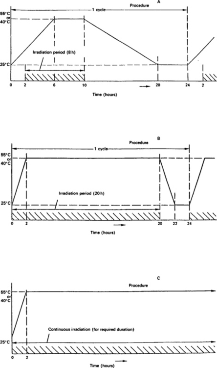
Fig. 3.8 Spectral energy distribution and permitted tolerances (reproduced from BS 2011:Part 2.1SA:1977 by kind permission of BSI)
Figure 3.9 shows the permitted tolerances for spectral energy distribution.

Fig. 3.9 Permitted tolerances for spectral energy distribution (reproduced from BS 2011: Part 2.1Sa:1977 by kind permission of BSI)
There are three types of test:
A 24 h cycle, with 8 h irradiation and 16 h darkness – repeated as required. This test approximates to the most severe natural conditions.
A 24 h cycle, with 20 h irradiation and 4 h darkness – repeated as required. This test is applicable where the principal interest is in degradation effects.
Continuous irradiation as required. This is a simplified test for the assessment of heating effects on specimens with low thermal capacity.