
General
12.1 Introduction
This section of the book is designed to include topics that apply to all of the other sections (e.g. the requirements for quality) or topics that are generally applicable to the majority of sections.
12.2 Design
Equipment needs to be designed to survive and work in a wide range of environments, from severe (i.e. one to which no controls or conditions are applied) to benign (i.e. one in which the ambient conditions are closely controlled at a predetermined level – for example, in a temperature controlled room).
It is usually a mandatory requirement of contracts that all equipment that is provided shall be expected meet all of the performance requirements for the environment in which that equipment is intended to operate.
The design of equipment shall be an optimum between:
• the environmental resistance of unprotected equipment;
• the protection of equipment from environmental influences;
• the restrictions found during transportation, storage and use of that equipment.
12.2.1 Equipment survival
Equipment needs to be designed so that it can operate in and survive:
• the effects of short-term extreme environmental conditions which may directly cause malfunction or might normally destroy the equipment.
Note: Short-term environmental conditions may occur at any time during an equipment’s lifetime and whilst equipment may be unaffected by an extreme condition when new, it may fail when subjected to the same condition after being used for a long period, due to the effect of ageing.
12.2.2 Earthquakes
Equipment during transportation or whilst in service, may be subjected to short duration, random, dynamic forces (e.g. stresses induced in the equipment as a result of earthquakes, explosions and during some phases of transportation).
Normally equipment suppliers will be required to provide proof of their equipment’s capability of withstanding a specified severity of transient vibration. This is in order to determine any possible mechanical weakness and/or degradation in specified performance and to demonstrate the mechanical robustness of specimens.
The time-history method described in IEC 68.2.57 is normally recommended for this purpose.
12.2.3 Lightning
Consideration should be given to the effects of lightning on the equipment. For protection against lightning, contracts frequently refer to EN 50124.2 which is a CENELEC requirement.
12.2.4 Flammability and fire hazardous areas
Another CENELEC recommendation concerns equipment being used in fire hazardous areas and for this three classes are foreseen by CENELEC for fixed installations.
1. Class FO – no special fire hazard envisaged. This is considered a normal service condition and except for the characteristics inherent to the design of the equipment, no special measures need to be taken to limit flammability.
2. Class F1 – equipment subject to fire hazard. This is considered an abnormal condition and restricted flammability is required. Self-extinction of fire shall take place within a specified time period. Poor burning is permitted with negligible energy consumption. The emission of toxic substances shall be minimised. Materials and products of combustion shall, as far as possible, be halogen free and shall contribute with a limited quantity of thermal energy to an external fire.
3. Class F2 – equipment subject to external fire. This is considered an abnormal condition and in addition to the requirements of Class F1, the equipment shall (by means of special provisions) be able to operate for a given time period when subjected to an external fire.
12.2.5 Fire protection
Materials shall be expected to conform to those requirements defined in EN 60721 or have the agreement of the customer concerned.
12.3 RAMS
RAMS is an acronym for Reliability, Availability, Maintainability and Safety. Each term is defined as follows:
• Reliability. The probability that a piece of equipment can perform a required function under given conditions for a specified period of time.
• Availability. The ability of a product to be in a state to perform a required function under given conditions at a given instant in time or duration.
• Maintainability. The probability that a given maintenance action can be carried out within a stated time interval, when that maintenance is carried out under stated conditions and using stated procedures and resources.
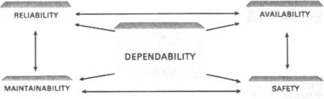
As a subject RAMS could form the basis of an entire book, but basically it covers all the criteria which make a piece of equipment dependable. Dependability is defined as being the ability of a product to perform one or several required functions under given conditions.
Equipment dependability is a major contributor to the quality of service offered by a device and the four major criteria that produce a dependable device are all inextricably linked. For example, you cannot have a safe device if it requires dangerous procedures to maintain it. Similarly, you would only expect a piece of equipment to be instantly available if it had good reliability.
Further reading on RAMS can be found in the following specifications:
• IEC 60300 – Reliability and maintainability management.
• BSI Handbook No. 22 Part 2 (1992) Reliability and Maintainability.
• BS EN 61069 – Dependability for industrial process measurement and control systems.
• EN 50126 – Railway applications: The specification and demonstration of dependability, Reliability, Availability, Maintainability and Safety (RAMS).
The following subsections offer only a small selection of typical requirements you may expect to find in a contract concerning RAMS requirements.
12.3.1 Reliability
The required reliability for each module is usually specified (by the end user) in individual specifications consistent with their requirements for overall system reliability.
The manufacturer will be required to provide reliability data for all equipment together with supporting evidence for the figures used.
12.3.2 Maintainability
For ease of maintenance, all equipment provided needs to have easily accessible test points to facilitate fault location and modules should be constructed so as to facilitate the connection of test equipment such as logic analysers or emulators, as well as test ROMs.
To assist with testing and fault location provision shall be made for isolating functional areas within each module.
Under workshop conditions it should be possible to gain access to all circuitry while operating, with a minimum of effort required, to partially dismantle the module concerned with the assumption that there will be a minimum of risk to the components, or the testing maintenance staff.
Special connecting leads, printed wiring extension boards and any other special items required for maintenance purposes, together with the mating half of all necessary connectors, will be assumed to be supplied by the manufacturer.
During operation, the storage of data obtained from the various systems and modules shall indicate each technical event and any perceived malfunction. The technical events may be overwritten after an agreed period. This data shall be stored in a way that is easily accessible by maintenance staff at first line and shall be readable from a remote position.
It should be noted that certain environmental tests may weaken electronic equipment and cause greater susceptibility to failure from the effects of the next or following environmental tests.
12.3.3 First line maintenance
It is normally stipulated that all equipment should be maintained at first line, on a European scale, without having to rely on the availability of multiple types of test installations.
12.3.4 Life
Equipment is normally expected to have been designed to have a useful life of not less than 20 years. ‘Useful life’ normally means ‘the period for which the equipment will continue to operate with the specified level of reliability’.
No components should, therefore, be used (so far as can be ascertained at the time of manufacture) for which spares cannot be fully guaranteed to be available throughout the life of the equipment.
12.3.5 Modifications
Modification states should be encoded such that they appear in all test reports printed at first line and (where possible) indicated on the equipment itself.
12.3.6 Protection against unauthorised access
The ‘access’ level defines who has access, reason for access and how access shall be achieved, thereby guarding against unauthorised access by others.
For each of the particular operations below, personnel performing these functions will require to meet certain criteria. CENELEC states that these shall be defined in respect of:
CENELEC also states that ‘protective measures should guard against access which is:
12.3.7 External conditions
Protection, as recommended by CENELEC, can normally be achieved by means additional to the equipment itself. For example:
12.3.8 Waste
Under new regulations currently being discussed and finalised by the European Commission, all suppliers will be required to provide details of any waste that their equipment (and/or the processes that manufactured their equipment) will generate for the following circumstances:
It is normally incumbent upon the supplier to prove their capability for not only producing environmentally acceptable equipment but also their ability to eventually destroy time expired or unusable equipment so that it does not cause any waste that is not easily degradable.
In all cases, the requirements of ISO 14001 concerning environmental protection and the prevention of pollution must be met.
12.3.9 Railway equipment
The railway requirements for Reliability, Availability and Maintainability are very closely linked with their exceptional safety record and because of this they are very specific in their contracts particularly with regard to the installation of equipment.
12.3.9.1 Railway (track) equipment
The physical size of the equipment is restricted so as to allow staff to pass unhindered and shall not cause any interference with minor track maintenance activities.
Track equipment needs to be sufficiently robust to allow their survival in the railway environment.
Track equipment has to be capable of withstanding, without deterioration or malfunction, all vibrations and shocks that occur in service.
Track equipment must be capable of meeting the Vibration, Shock and Bump tests as described in the IEC 68.2.6/27/29/57 standards.
12.3.9.2 Trainborne equipment
Trainborne equipment has to be capable of transmitting data to the trackside and/or contain a removable data storage unit. A single industry standard is required for access to each individual recorded data file.
For diagnostic purposes, the railways require that all trainborne modules can be exercised from depot based equipment using a standardised interface.
12.3.9.3 Installation of railway equipment
The installation and arrangement of equipment on the vehicles is usually determined by agreement between the manufacturer of the electric equipment, the manufacturer of the vehicle and the end user concerned.
With due regard to its location and the method of installation on the vehicle, the electronic equipment must be capable of operating correctly in spite of snow (especially powdery snow), dust and other conditions to which rolling stock is normally exposed whilst in service.
In addition to vibrations, shocks and bumps, operation of electronic equipment should not be influenced by any electromagnetic fields present inside the vehicles.
The supply to the equipment should, if possible, be provided by a separate conductor connected as directly as possible to the source. This conductor should be used only for the supply to electronic circuits.
The installation of the electronic equipment should be arranged so as to reduce the effects of external electrical disturbances. Protection at the source is recommended if this method presents no major disadvantage.
The railway concerned will be expected to inform the manufacturer if one pole of the battery of the vehicle is earthed to the frame.
If several manufacturers supply electronic equipment having common direct connections, a reference potential needs to be established by mutual agreement between the users and the manufacturers.
12.3.9.4 Initialisation
Initialisation routines that exercise all functions and display in-service data to the driver and a confirmation of the results, at any supplementary test position, shall be made available.
12.3.9.5 General provisions governing acceptance of railway products – technical approval
The general conditions governing acceptance of railway products for use is contained in Table 12.1.
Table 12.1
Conditions governing acceptance of railway products for use
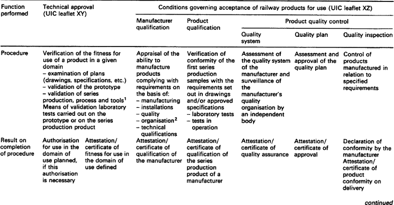
1The manufacturer must be qualified beforehand.
2The quality organisation may be a quality system.
12.3.9.5.1: Technical approval The technical approval procedure defined in UIC leaflet XY draft No. 5 specifies the conditions to be observed and the procedure to be used to authorise certain products for use in railway operation as well as the measures to be taken prior to their use or commissioning.
12.3.9.5.2: Manufacturer’s responsibility The manufacturer is expected to retain responsibility for the quality of products delivered and for observance of all regulatory or contractual requirements defined in the technical documents concerning the product.
12.3.9.5.3: Component certification In addition to the CENELEC Electronic Components Committee (CECC) and the International Electrotechnical Commission, Quality Assessment System for Electronic Components (IECQ) procedures for component certification, each product listed shall be accompanied by the identification of the manufacturer, a description of the product, the conditions for use, the relevant definition and the associated documents.
12.4 Fire
A fire will normally start when sufficient thermal energy from, for example, a burning cigarette or an electric short circuit is supplied to a combustible material. Following ignition, the fire will then produce its own thermal energy. Some of which will be used as feedback to maintain combustion and some transferred via radiation and convection to other materials. These materials may also ignite and spread the fire.
The environmental conditions relating to the occurrence, development and spread of fire within a building and its effect on electrotechnical products exposed to fire is primarily covered by Section 8 (Fire Exposure) of IEC 721.2. This section provides background information for selecting the appropriate parameters and severities related to exposure of products to fire. More detailed information on fire condition characteristics and fire hazard testing is contained in specialist documentation.
12.4.1 Introduction
12.4.1.1 The development of fire
The development of the fire generally consists of three processes:
As a rule, radiation, convection and flame spread are the dominant physical factors.
12.4.1.2 Fire growth
Once a fire has started in a space (e.g. a room) its growth and spread is determined by:
• arrangement of the fuel or fire load, its distribution, continuity, porosity and combustion properties;
• aerodynamic conditions of the space;
During the growth of a fire, a hot layer of gas builds up under the ceiling of the space. Under certain conditions, this gas layer can give rise to a rapid fire growth and flashover might occur.
12.4.1.3 Flashover
One normally defines flashover as the time when flames begin to emerge from the openings of the space, which correlates, with a temperature of 500°C to 600°C in the upper gas layer.
Flashover marks the transition from the growing fire (pre-flashover) to the fully developed fire (post-flashover).
12.4.1.4 Pre-flashover
A pre-flashover fire primarily concerns the operation and function of products (e.g. detectors, alarm systems, associated cables and sprinklers, etc.) that are vital to maintaining the level of safety required for escape and/or the rescue of people caught in a fire.
12.4.1.4.1: Characteristics of pre-flashover fire The ignitability properties of exposed material depends on:
12.4.1.4.2: Fire hazard of a pre-flashover The fire hazard of a pre-flashover situation is normally considered in terms of a series of probabilities, which depends on:
• the presence of ignition sources;
• the product fire performance properties;
• the presence/operation of detection and suppression devices;

12.4.1.5 Post Flashover
Whilst most standards are normally concerned with conditions during the pre-flashover stage of a fire, conditions following flashover must also be considered. A post-flashover fire can seriously damage some of the structural and load bearing elements of a building and the fire can then, quite easily, spread from one fire space to another via partitions and ventilation systems. This can, of course, seriously damage electrical equipment located in these voids. For example, in a large space it is quite possible that a fire, small in relation to that space, could be large enough to damage some of the structural elements in the post-flashover state. An important factor of the post-flashover fire, which is often overlooked, is the amount of smoke and toxic gases that can affect people in escape routes and remote safety areas in a building. Smoke and toxic gases can also significantly affect equipment.
12.4.1.5.1: Characteristics of post-flashover fire The main characteristics of a post-flashover fire are:
• the geometrical and thermal data for external flames;
• the smoke and its optical properties;
• the composition of the combustion products, particularly corrosive and toxic gases.
The possibility of a large external fire spreading from one storey to another in the same building (and eventually from one building to another) must also be considered. For these cases the first three characteristics – i.e. primarily gas temperature, geometrical and thermal data for the flames emerging from the window openings – are the most relevant.
12.4.1.5.2: Characteristics of smoke and gases as a fire product Smoke is a mixture of heated gases, small liquid drops, and solid particles from the combustion. During a fire (pre- and post-flashover), smoke will be distributed within the building through the air flow between rooms and via ventilation ducts, etc. In most circumstances this can have disastrous effects because smoke can not only damage and in some cases even destroy property, it can also prevent the functioning of critical equipment. Most of the effects of smoke are of a chemical nature and the most prevalent is destruction or damage to electrotechnical products, in particular corrosion caused by hydrogen chloride, which is a substance in smoke.
Metal surfaces, exposed to air under normal (non-fire) conditions, often have a chloride deposit up to 10 mg/m2. Such an amount is normally not harmful. However, after exposure to smoke from a fire involving polyvinyl chloride (PVC), a surface contamination of up to thousands of milligrams per square metre can be found, often causing significant damage. Chloride contamination of electrotechnical equipment can be removed by, for instance, detergents, solvents, neutralising agents, ultrasonic vibrations, and clean air jets, but the procedures are not always effective, sometimes giving a temporary but not permanent cure.
Experiments, involving PVC coated electrical wires and carried out on a scale large enough to be representative of real fires, are currently in hand.
12.4.2 Building designs
In the design of buildings, the fire design of load bearing structural elements and partitions is normally considered as a national problem and directly related to the results of standard national (and when available) international fire resistance tests. In such tests, the specimen is exposed, in a furnace, to a temperature rise, which is varied with time and within specified limits, according to the particular test being used.
Over the last decades, rapid progress has been made in the development of analytical and computational methods for determining the fire design of load bearing and separating structures and structural elements. In the long term, it is foreseeable that this will develop into an analytical and/or computational design, directly based on a natural fire exposure. These will be specified with regard to the combustion characteristics of a fire load and the geometrical, ventilation and thermal properties of the fire space.
12.4.3 Test standards
Fire tests on building materials, components and structures normally focus on the characteristics of pre-flashover fire. Simplified full-scale (i.e. room) tests for surface products against smoke and in particular toxic combustion products are already available, but considerable development work needs to be completed before a useful small-scale test is available.
If no mathematical model of a small-scale test is available, the test results should be statistically correlated directly to full-scale test data. If a validated mathematical model of a small-scale test exists, important material characteristics controlling the space fire growth can be given quantitative values which can then be used as input data in mathematical models of full-scale pre-flashover space fire for specified scenarios.
With a view to practical, long-term use the results of small-scale reaction to fire tests to predict fire hazard should be based on a fundamental and scientific approach.
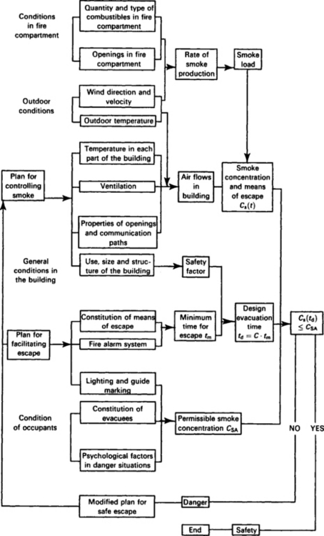
Figure 12.4 outlines the structure of such an approach.
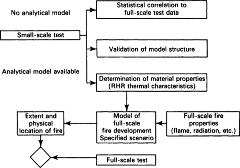
Fig. 12.4 Combination of basic property tests and mathematical models for assessing the contribution of a tested material or product to the overall fire safety (reproduced from the equivalent standard BS EN 60721.2.8 by kind permission of the BSI)
12.4.4 Other related standards and specifications
| IEC 60695 Series | Fire hazard testing – Guidance, tests and specifications for assessing fire hazard of electrotechnical products |
| ISO 5657 | Fire tests – Reaction to fire – Ignitability of building products |
| ISO 5658 | Reaction to fire tests – Spread of flame on building products and vertical configuration |
| ISO 5660 | Fire tests – Reaction to fire – Rate of heat release from building products |
| ISO 9705 | Fire tests – Full scale room test for surface products |
| ISO TR 5924 | Fire tests – Reaction to fire – Smoke generated by building products (dual-chamber test) |
| ISO TR9112.1 | Toxicity testing of fire effluents – General |
12.4.5 Typical contract requirements – fire
In most contracts reference is made to the IEC 60695 series of standards which cover the assessment of electrotechnical products against a nominated fire hazard.
CENELEC, on the other hand, show the requirement for equipment to operate in fire hazardous areas as three distinct clauses, as follows:
• Class FO – no special fire hazard envisaged. This is considered a normal service condition and except for the characteristics inherent to the design of the equipment, no special measures need to be taken to limit flammability.
• Class F1 – equipment subject to fire hazard. This is considered an abnormal condition and restricted flammability is required. Self-extinction of fire shall take place within a specified time period. Poor burning is permitted with negligible energy consumption.
The emission of toxic substances shall be minimised. Materials and products of combustion shall, as far as possible, be halogen free and shall contribute with a limited quantity of thermal energy to an external fire.
• Class F2 – equipment subject to external fire. This is considered an abnormal condition and in addition to the requirements of Class F1, the equipment shall (by means of special provisions) be able to operate for a given time period when subjected to an external fire.
Materials are normally expected to confirm to those requirements defined in EN 60721.3.3 and EN 60721.3.4.
12.5 Quality Control and Quality Assurance
The principles of Quality Assurance and applications of standards in the ISO 9000 series are now widely accepted and the need has emerged for contracts to define common provisions concerning:
• general rules for acceptance for use of products adapted to the risks associated with their use;
• technical approval procedures for products;
• conditions for quality surveillance on the premises of product manufacturers;
Requirements with regard to quality are dependent on the level set by the end user in the contract. They normally fall into one of four levels.
12.5.2 Manufacturers
Manufacturers of products falling within quality levels 1, 2 and 3 (see Table 12.3) need to be qualified.
For requirement levels 1 and 2, qualification of the manufacturer shall require an evaluation of its quality system and its technical capabilities.
Level 3 requires only the evaluation of the manufacturer’s inspection, organisation and verification of its technical capabilities.
Level 4 requires the manufacturer to maintain documented proof that tests and inspections have been carried out and that they conform to the specific technical requirements contained in the relevant standards and specifications.
12.5.3 Products
Unless otherwise stated, all products are normally assumed to be qualified. This qualification will consist of verification of product conformity with the technical characteristics specified (drawings, specifications, etc.) and will be verified during initial series production.
12.5.4 Quality documents required
In accordance with the requirements of ISO 9000:
• the manufacturer shall draw up a quality plan describing the specific measures taken by the manufacturer to achieve and master the quality of their product;
• the plan shall specify the resources and the sequences of specific quality actions for the product and should include an inspection and audit schedule;
• inspection and test documents concerning the product shall be drawn up (test reports, inspection records, etc.) by the manufacturer/supplier.
12.5.4.2 Validation of the quality plan
Validation of the quality plan by the customer is normally carried out in two stages:
• formal validation of the document on completion of examination;
• validation of application of the document (on completion of an audit) and verification of implementation of any corrective action undertaken.
Table 12.2
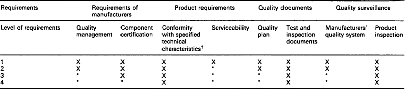
X Provision required by the railway.
• This provision or verification is not required.
1Technical characteristics may include specific tests carried out on initial parts, the definition and contents of which shall be specified in the technical document for the product.
Validation of the quality plan is not anticipated to relieve the manufacturer of its responsibility for quality!