
Electrical
9.1 Guidance
Electrical and electronic engineering is recognised as probably the largest and most diverse field of engineering and is concerned with the development, design, application and manufacture of systems and devices that use electric power and signals. Among the most important subjects in the field are electric power and machinery, electronic circuits, control systems, computer design, superconductors, solid state electronics, medical imaging systems, robotics, lasers, radar, consumer electronics and fibre optics.
9.1.2 Introduction
Electrical engineering can be divided into two main branches: electric power and electronics.
Electric power: Electric power is concerned with the design and operation of systems for generating, transmitting and distributing electric power.
One of the most important developments in the last 30 years has been the ability to transmit power at extremely high voltages in both the direct current (d.c.) and alternating current (a.c.) modes, reducing power losses proportionately.
Electronics: Electronic engineering deals with the research, design, integration and application of circuits and devices used in the transmission and processing of information.
Electronic engineers design circuits to perform specific tasks, such as amplifying electronic signals, adding binary numbers and demodulating radio signals to recover the information they carry.
9.1.3 Test categories
This sort of test requires the electronic assembly, or its subassemblies, to be subjected to a complete examination of its/their performance in order to determine whether it/they correspond to the specification.
Correct operation of all the electronic control equipment should be checked within the normal limits of system voltage, battery voltage and air pressure.
In particular, checks should be made to see that the operation of the equipment is not disturbed during start-up of any auxiliary services (e.g. lighting, an auxiliary set, compressor, etc.) and power circuits (e.g. a chopper, combustion engine, etc.). Checks should also be made to establish whether any interference produced by electronic control devices disturbs other equipment, in particular data transmission installations, safety devices, etc. (e.g. see EN 50155).
9.1.3.2 Dielectric test
The aim of this test which is carried out on printed board assemblies (by sampling) is to ensure components are not mounted too close to surrounding metal parts.
The test has to be carried out with the printed board connected in its place of operation. The test voltage (of a nominal frequency of 50 Hz or 60 Hz) is then applied for 1 minute between all the terminals (with the printed board short-circuited) and the metal rack of the electronic assembly.
For dielectric tests the r.m.s. value of the test voltage is as follows:
9.1.3.3 Voltage surge test
All terminals of the electronic equipment which are directly connected magnetically or statically coupled to external circuits and which are likely to produce voltage surges that could cause damage to electronic equipment are normally subjected to a voltage surge test.
During this test a surge voltage of an agreed waveform (see Table 9.2) is applied at the points of connection between the electronic equipment and external circuits of the operating equipment.
Table 9.2
Waveform of normally permitted voltage surges
| Û | 1.5kV ± 3% |
| Impedance (resistive) | 100Ω ± 20% |
| D | 50μs ± 20% |
The surge voltage should be applied in both directions (positive and negative) and in the case of power supply connections, the surge voltages should be superimposed on the nominal supply voltage.
The waveform parameters are normally agreed between the user and the manufacturer and are typically:
The test should be considered as satisfactory if the equipment continues to operate without malfunction or damage both during and following application of the voltage surge.
9.1.3.4 Cooling test
The electronic assembly under test is placed, without any voltage applied, in a room where the temperature is progressively lowered from the ambient temperature (25°C ± 10°C) to −25°C, or to the lowest agreed temperature over a period of time equal to or greater than 30 minutes.
The assembly is then kept for a further period of 2 hours at this low temperature with a permitted tolerance of ± 3°C.
At the end of this period, a performance test (see 9.1.3.1) needs to be carried out with the equipment kept at this low temperature.
9.1.3.5 Temperature-rise test (dry heat)
For this particular test, the electronic assembly (which is normally supplied with power) is placed in a room where the temperature is progressively raised from the ambient temperature (25°C ± 10°C) to 70°C (with a tolerance of ± 2°C) or to the highest agreed temperature over a period of time equal to or greater than 30 minutes.
The assembly should then be kept for 6 hours at this temperature, at the end of which a performance test should be carried out.
9.1.3.6 Temperature-rise test (damp heat)
The electronic assembly is placed, without any voltage being applied, in a chamber where the temperature is raised from the ambient temperature (25°C ± 10°C) to 55°C ± 2°C over a period of time between 1½] hours and 2½ hours. The relative humidity being stabilised between 80% and 100%.
The temperature is then maintained for a further period of 10 hours within the limits of 55°C ± 2°C, with a relative humidity of 95% to 100%.
At the end of this time, the temperature is lowered to the ambient temperature (25°C ± 10°C), over a period of 3 hours, with the relative humidity being between 80% and 100%. After this cycle, a performance test and a dielectric test needs to be completed.
Note: IEC Test 68.2.30: Damp heat, cyclic (12 + 12 hour) is the preferred test as it more closely represents those conditions in which equipment will be stored or operated. (See paragraph 4.4.3.)
9.1.3.7 Test in a corrosive atmosphere (e.g. salt mist)
In this test the test chamber is kept tightly closed and if the test includes the necessity for a salt solution, it should continue without interruption during the whole conditioning period. The duration of the test is chosen so as to suit the intended purpose and should be subject to an agreement between the user and the manufacturer.
At the end of the test, the equipment is then washed under a running tap for 5 minutes or rinsed in distilled or demineralised water. It is then shaken by hand (to remove any droplets of water) and stored under standard atmospheric conditions in the testing area for not less than 1 and not more than 2 hours.
After this storage period, the components are then subjected to a visual examination, followed by measurements and verification tests necessary to check their correct operation.
Note: IEC 68.2.11 and 68.2.52 are the recommended tests for salt mist and cyclic salt mist environmental parameters. (See paragraphs 6.4.1 and 6.4.3.)
9.1.3.8 Combined dust, humidity and heat test
The electronic assembly, in operating condition, is placed in a room where the temperature is progressively raised from the ambient temperature (25°C ± 10°C) to 70°C or to the highest agreed temperature (with a tolerance of ±2°C) for between 1½ hours and 2½ hours (depending on the customer), with a relative humidity of 80% to 100%.
Dust (which is normally specified and, if necessary, provided by the user at the time of specifying the item) is sprayed over the electronic assembly. The quantity and the method of application are subject to an agreement between the user and the manufacturer.
At the end of this test, a performance test and a dielectric test should be carried out.
Note: IEC 68.2.68: Environmental testing procedures – Dust and sand is a more stringent test than this basic test and is recommended (see paragraph 7.4.4).
9.1.3.9 Vibration, shock and bump test
The complete electronic assembly (or subassembly) together with any auxiliaries and mounting arrangements (including its shock absorbing devices if the equipment is designed for mounting on such devices) should be subjected to the tests in three orthogonal planes under the ambient temperature condition of the testing area.
For these tests, the equipment should be secured in a suitable position to a machine producing sinusoidal vibrations with an adjustable amplitude and frequency.
In order to determine the possible existence of critical resonant frequencies producing resonance during this test, the frequency should be varied progressively from 1 Hz to 100 Hz within a time of not less than 4 minutes. The amplitude of the oscillations being a function of the frequency.
If resonance is produced, the corresponding frequency should be maintained for a few minutes in each case.
The equipment is then subjected to a test with sustained vibrations for not less than 15 minutes (to be agreed between the user and the manufacturer), either at the critical frequencies or, otherwise, at a frequency of 10 Hz.
9.1.3.10 Watertightness test
As electronic equipment is generally mounted either inside a room or a vehicle or in external boxes, there is no real need to carry out watertightness tests. In exceptional cases, however, tests can be carried out in accordance with clause 7 of IEC 165 and clause 8 of IEC 490.
Note: Current thinking suggests that watertightness tests are, however, very relevant in some circumstances (e.g. equipment exposed to rain, water jets, etc.) and the reader is referred to Section 6.4 for the appropriate tests.
9.2 Typical contract requirements – electrical
The requirement for equipment to conform to various environmental specifications is becoming commonplace in many of today’s contracts. More and more specifications are being used to describe the various conditions that equipment is likely to experience when being used, stored or whilst in transit.
The following are the most common environmental requirements found in modern contracts concerning electrical conditions.
9.2.1 Supply voltages
Equipment will normally be required to operate on one particular voltage. There are, however, occasions when they may be required to be capable of being switched between various values (e.g. 110 V and 240 V). Equipment manufacturers should be aware (and users should specify) very precisely in the contract exactly what type and range of voltages, power consumption and so on have been taken into account.
9.2.1.1 Primary main (a.c.)
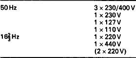
In today’s world market the nominal supply voltage (Un) of equipment can be any of the following values:
9.2.1.2 Supply from an accumulator battery
The nominal voltage for equipment supplied by an accumulator battery is the voltage specified for that particular battery. This voltage range can be quite enormous (depending on the application of the equipment) and should be clearly specified in the technical annex attached to the contract. The following are some examples:
Table 9.4
| Either | 24V, 48V, 72V, 96V, 110V | For mobile/transportable equipment |
| Or | 12V, 24V, 36V, 48V, 60V, 72V, 144V | For fixed equipment |
The reader should note that these nominal voltage values are provided only as standardised reference values to assist in the design of equipment.
They should not be considered as off-load battery voltages which are determined as functions of the type of battery, the number of cells and the operating conditions.
Another requirement is usually that all electronic equipment supplied by accumulator batteries without a voltage stabilising device must operate satisfactorily for all values of supply voltage within the range defined in Table 9.5 (measured at the input terminals of the equipment).
Table 9.5
| Nominal voltage | Un |
| Minimum voltage | 0.7Un |
| Rated voltage | 1.15Un |
| Maximum voltage | 1.25Un |
When equipment is supplied with power alternately from an accumulator battery and a stabilised source (d.c.), the equipment should operate satisfactorily under all conditions.
9.2.2 Variations in supply voltage
The following are the maximum CENELEC permitted variations
Table 9.6
Maximum permitted a.c./d.c. variations
| AC/50 Hz: Voltage: | ±10/15% |
| Frequency: | ±2% (class 2 IEC 77B) |
| ±4% (class 3 IEC 77β) | |
| AC/16⅔ Hz: Voltage: | ±20% (catenary) |
| Frequency: | ±2% |
| DC Voltage: | ±10/20% without battery or by Pb battery |
| Ripple: | ±16/29% by Ni/Cd battery |
For supply voltages less than 0.7Un’ every precaution must be taken to prevent any damage being caused to electronic equipment which may adversely affect its subsequent satisfactory operation.
One frequent contract requirement is that voltage fluctuations lying between 0.6Un and 1.4tUn (and not exceeding 0.1 seconds) should not affect operating equipment – particularly during start-up of auxiliary equipment and/or voltage oscillations of battery chargers.
Also, voltage fluctuations lying between 1.25Un and 1.4Un (and not exceeding 1 second) should not cause damage to equipment.
Note: equipment need not be fully operational during these fluctuations.