
Humidity
4.1 Guidance
The atmosphere is normally described as ‘a shallow skin or envelope of gases surrounding the surface of the Earth which is made up of nitrogen, oxygen and a number of other gases which are present in very small quantities’. While the ratio of these components shows no appreciable variation either with latitude or altitude, the water vapour content of the atmosphere is subject to extremely wide fluctuations. The amount of water present in the air is referred to as humidity.
When air and water come into contact, they will exchange particles with each other (i.e. the air particles will pass into the water and water particles will pass into the air in the form of vapour). There is always a certain amount of water vapour present in the air and a certain amount of air present in water and there is always a constant movement between the two mediums.
When only a small amount of water vapour is present in the air, more particles of water will pass from the water into the air than from the air into the water and the water will gradually dry up or evaporate. Conversely, if the amount of water vapour in the air is large, then as many particles of vapour will pass from the air into the water as from the water into the air, and the water will not evaporate. In such a case the air is said to be ‘saturated’ or, in ordinary language, that it holds as much water vapour as it can contain.
Water vapour is collected in the air above the oceans and is carried by the wind towards the land masses. The amount of water vapour in the air varies greatly depending on the place and season. In general, evaporation is most rapid at high temperatures and slower at lower temperatures. We may, therefore, expect to find the greatest amount of water vapour over the oceans near the Equator and the smallest amount over the land in a cold region such as north-eastern Asia in winter. However, even when the surface is covered with snow and ice, water evaporation may take place and occasionally during a long frost, the snow will gradually disappear without melting.
Except for the water vapour present, the composition of the atmosphere near the surface of the Earth up to a height of some 2000 ft is practically uniform throughout the globe. However, at greater altitudes, i.e. above the atmospheric boundary known as the tropopause (which is found at an average height of about 25 000 ft in polar regions and rises to 55 000 ft over the Equator), there is practically no water vapour, or water, in any form.
4.1.2 Introduction
Temperature and the relative humidity of air (in varying combinations) are climatic factors which act upon a product during storage, transportation or operation. Humidity and the electrolytic damage resulting from moisture mostly affects plug points, soldered joints (in particular dry joints), bare conductors, relay contacts and switches. Humidity also promotes metal corrosion (see Chapter 7 – Pollutants and contaminants) owing to its electrical conductivity.
But in many cases, environmental influences such as mechanical and thermal stresses are merely the forerunner of the impending destruction of components by humidity – especially as the majority of electronic component failures are caused by water (Ref. 1).
In a recent report by the European Rail Research Institute (ERRI) the problems caused by humidity were discussed and part of that report provided the curve in Figure 4.1 as an example of how the water content of air varies with temperature. Water content (indicated by Relative Air Humidity – RAH or RH) corresponds to the ratio between the actual vapour pressure and the saturation vapour pressure. The water content varies with temperature.

Humidity (in the context of this book) covers Relative Humidity, Absolute Humidity, Condensation, Adsorption, Absorption and Diffusion and details of these ‘subsets’ are provided in the following paragraphs.
Note: At a fixed air pressure, the absolute air humidity (defined as the actual mass of water per unit of air volume in grams per cubic metre) is given by the air temperature (in degrees Celsius) and the relative air humidity (as a percentage).
4.1.2.1 Relative and Absolute Humidity and their effect on equipment performance
The performance of virtually all electronic equipment is influenced and limited by its internal temperature which, in turn, is dependent on the external ambient conditions and on the heat generated within the device itself. Fortunately, most electronic components (especially resistors) will normally remain dry when under load owing to the amount of internal/external heat dissipation. Indeed, many components either have to be derated in order to improve their reliability or, for reasons of circuit function, only energised intermittently.
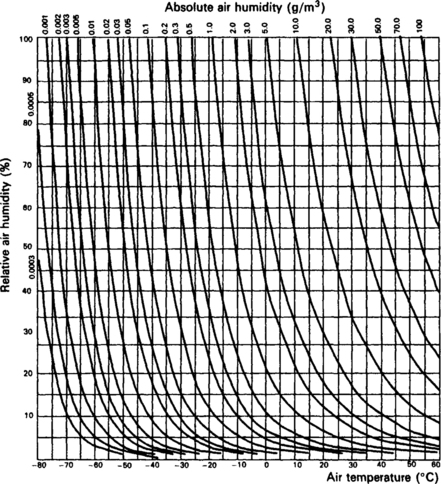
Fig. 4.2 Constitutional diagram for humid air (reproduced from the equivalent standard BS 7527 Section 2.1:1991 by kind permission of the BSI)
4.1.2.1.1: Externally mounted equipment Equipment and components that are mounted in external cabinets or on the outside of a vehicles run the risk of coming into contact with water or water vapour (e.g. drifting snow, fog, dew, rain, spray water or water from hoses).
The equipment must, therefore, be adequately protected from such humidity in order to prevent the ingress of vapour into the system within the casing.
4.1.2.1.2: Housed equipment – humidity In most locations (e.g. cabinets, equipment rooms, workshops and laboratories) although temperatures above 30°C may often occur, they are normally combined with a lower relative humidity than that found in the open air. In other rooms (e.g. offices), however, where several heat sources are present, temperatures and relative humidities can differ dramatically across the room.
The Sun also plays its part because in certain circumstances (such as when equipment is placed in an unventilated enclosure), the intense heat caused through solar radiation can generate relative humidities in excess of 95% when combined with:
4.1.2.1.3: Equipment used in tunnels When equipment is being transported through tunnels (e.g. when mounted on a train or vehicle) rapid external ambient temperature variations can result with a rate of change of external temperature of as much as 3°C/sec and with a maximum variation of 40°C. This can be a serious problem and must be considered when designing equipment.
4.1.2.2 Condensation
Condensation occurs on a specimen when its surface temperature is lower than that of the dew point (i.e. the temperature with a relative humidity of 100% at which condensation occurs). A direct relationship which can change electrical characteristics (e.g. decrease surface resistance, increase loss angle) thus exists between the absolute point at which atmospheric vapour condenses into droplets (i.e. the dew point), absolute humidity and vapour pressure.
If a piece of equipment has a low thermal time constant, condensation (normally found on the surface of the equipment) will occur only if the temperature of the air increases very rapidly, or if the relative humidity is very close to 100%. Sudden changes in temperature (particularly when equipment is mounted on a vehicle entering or leaving a tunnel) may cause water to condense on parts of equipment and leakage currents can occur.
4.1.2.3 Adsorption
Adsorption is the amount of humidity that may adhere to the surface of a material and depends on the type of material, the surface structure and the vapour pressure. This layer of water (no matter how small) can cause electrical short circuits and material distortion etc.
4.1.2.4 Absorption
The quantity of water that can be absorbed by a material depends largely on the water content of the ambient air. The speed of penetration of the water molecules generally increases with the temperature.
4.1.2.5: Diffusion Water vapour can penetrate encapsulations of organic material (e.g. a capacitor or semiconductor) by way of the sealing compound and into the casing. This factor is frequently overlooked and can become a problem, especially as the moisture absorbed by an insulating material can cause a variation in a number of electrical characteristics (e.g. reduced dielectric strength, reduced insulation resistance, increased loss angle, increased capacitance).
4.1.2.6 Protection
The effects of humidity mainly depend on temperature, temperature changes and impurities in the air. There are three basic methods of protecting the active parts of electronic components from humidity:
• heating the surrounding air so that the relative humidity cannot reach high values; This method normally requires a separate heat source which (especially in the case of equipment mounted in external cabinets) usually means having to have a separate power supply. This method is disadvantaged by the reliability of the circuit being dependent on the efficiency of the heating.
• hermetically sealing components or assemblies using hydroscopic materials; This is an extremely difficult process as the smallest crack or split can allow moisture to penetrate the component particularly in the area of connecting wire entry points. Metal, glass and ceramic encapsulation do nevertheless produce very satisfactory results.
• ventilation and the use of moisture absorbing materials. Most water retaining materials and paint, etc. are suitable for the temporary absorption of excessive high air humidity in the casing, which, because of the risk of pollution and dust penetration, cannot be fully ventilated (i.e. air exchange with the outside temperature is not possible).
4.1.3 Test standards
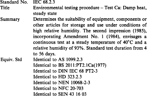
| IEC 68.2.3 | Environmental testing procedures – Test Ca: Damp heat, steady state |
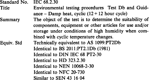
| IEC 62.2.30 | Environmental testing procedures – Test Db and guidance: Damp heat, cyclic (12 + 12 hour cycle) |
| IEC 68.2.38 | Environmental testing procedures – Test Z/AD: Composite temperature/humidity cyclic test |
| IEC 68.2.56 | Environmental testing procedures – Test Cb: Damp heat, steady state, primarily for equipment |
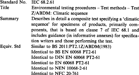
| IEC 68.2.61 | Environmental testing procedures – Test Z/ABDM: Climatic sequence |
4.1.4 Other related standards and specifications
| EN 50123 | Railway applications – d.c. switchgear for stationary installations in traction system – General |
| EN 50125 | Railway applications – Environmental conditions for rolling stock equipment |
| EN 50155 | Railway applications – Environmental conditions for non-rolling stock equipment |
| ERRI Question AI18 | Report No. 4. Use of electronic components in signalling |
| IEC 68.1 | Environmental testing procedures – General and guidance |
| IEC 68.2.14 | Environmental testing procedures – Test N: Change in temperature |
| IEC 68.2.2 | Environmental testing procedures – Test B: Dry heat |
| IEC 68.2.28 | Environmental testing procedures – Guidance: Damp heat tests |
| IEC 721.1 | Classification of environmental conditions – Environmental parameters and their severities |
4.2 Typical contract requirements – humidity
The requirement for equipment to conform to various environmental specifications is becoming commonplace in today’s contracts. More and more specifications are being used to describe the various conditions that equipment is likely to experience when being used, stored or whilst in transit.
The following are the most common environmental requirements found in modern contracts concerning humidity.
4.2.1 External humidity levels
Equipment that is operated adjacent to the sea shore and therefore subject to extreme humidity must be able to function equally well as the same equipment housed in the low humidity of the desert.
Equipment should be designed and manufactured to meet the following external humidity levels (limit values), over the complete range of ambient temperature values as shown in Chapter 2.
Table 4.1
Humidity – External humidity levels
| Duration | Limit value |
| Yearly average | 75% relative humidity |
| On 30 days of the year, continuously | 95% relative humidity |
| On the other days, occasionally | 100% relative humidity |
| On the other days, occasionally | 30g/m3 occurring in tunnels |
Meteorological measurements made over many years have shown that, within Europe, a relative humidity greater (or equal to) 95% combined with a temperature above 30°C does not occur over long periods in free air conditions.
4.2.2 Condensation
Condensation has always been a problem when designing and using equipment and the humidity of air and the possible formation of condensed water must always be considered. The requirement most frequently stated in contracts is that ‘operationally caused infrequent and slight moisture condensation shall not lead to malfunction or failure of the equipment’.
4.2.3 Indoor installations
Another contract requirement is that in all indoor installations, provision must be made for limiting the humidity of the ambient air to a maximum of 75% at –5°C.
4.2.4 Equipment being transported through tunnels
Rapid external ambient temperature variations resulting from equipment being transported through tunnels is a known problem and should always be taken into consideration. For the purpose of most specifications used in contracts, the rate of change of external temperature is normally assumed to be 3°C/sec with a maximum variation of 40°C.
4.2.5 Equipment installed in tunnels
Installations in tunnels may experience 100% humidity during start-up. Although this is normally specified as an abnormal operation, contracts (particularly railway contracts) nevertheless stipulate that suitable provisions must be incorporated to avoid incorrect operations. Normally these stipulations are agreed between purchaser and supplier and is part of the contract.
4.2.6 Equipment in cubicles and cases
Quite frequently, contracts will stipulate that the design of equipment shall always take into account temperature rises within cubicles and equipment cases in order to ensure that the components do not exceed their specified temperature ranges.
4.2.7 Peripheral units
For peripheral units (e.g. measuring transducers, etc.) or equipment employed in a decentralised configuration (i.e. where ambient temperature ranges are exceeded), contracts normally require that ‘the actual temperature occurring at the location of the equipment concerned shall be utilised when designing equipment’.
4.2.8 Tests
Another normal requirement is that ‘all proposed candidate equipment, components or other articles must be tested in their production configuration without the use of any additional external devices that have been added expressly for the purpose of passing humidity testing’.
4.2.8.2 Procuring specifications
When tested, it is usually a mandatory requirement for the sample (component, equipment or other article) ‘to perform as stipulated in the procuring specification and over the designated humidity range’.
4.2.8.3 Test methods
Test methods for determining the suitability of specimens may be selected from:
| IEC 68.2.3 | Environmental testing procedures – Test Ca: Damp heat and tests |
| IEC 68.2.30 | Environmental testing procedures – Test Db and guidance: Damp heat, cyclic (12 + 12 hour cycle) |
| IEC 68.2.38 | Environmental testing procedures – Test Z/AD: Composite temperature/humidity test |
| IEC 68.2.39 | Environmental testing procedures – Test Z/AMD: Combined sequential cold, low air pressure and damp heat test |
| IEC 68.2.56 | Environmental testing procedures – Test Cb: Damp heat, steady state, primarily for equipment |
| IEC 68.2.61 | Environmental testing procedures – Test Z/ABDM Climatic sequence |
4.3 Values and Ranges
Guidance on geographical values and ranges of humidity have been taken from the latest issue of IEC 721 standard. These figures are based on observations over a period of not less than 10 years and represent conditions frequently met by products whilst being transported, stored, installed or used.
Except where stated, all values given represent the maximum and minimum humidity experienced by a particular piece of equipment in a particular location and situation.
Deviation from the humidity tables shall be subject to acceptance by demonstration that the equipment is suitable for service.
4.4 Tests
This section details some of the test standards which may be applied to equipment and contains:
• details of the most used environmental tests that a purchaser will normally require a manufacturer to adhere to;
Note: Full details of each of these recommended tests are contained in the relevant ISO, IEC or other standard. A complete list of these standards is supplied in the reference section of this book. Copies of all these standards may be obtained from any National Standards Organisation.
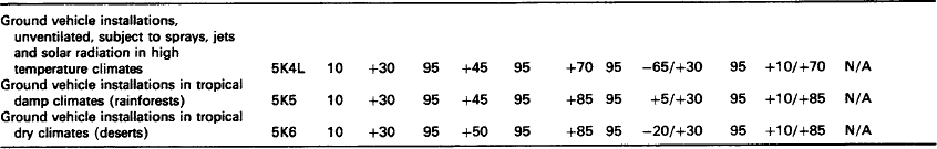
Table 4.2

1The choice of classification is dependent upon the type of climate in which the equipment will be installed.
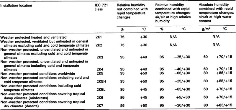
Table 4.4
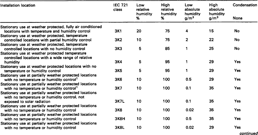

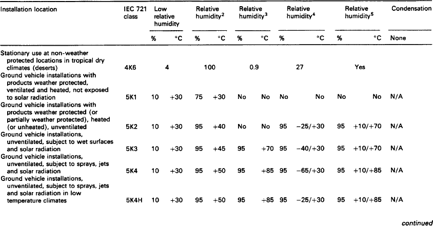
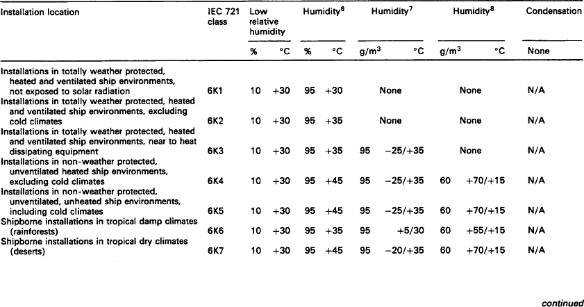

1The choice of classification is dependent upon the type of climate in which the equipment will be installed.
2Relative humidity, not combined with rapid temperature changes, except in engine compartments of vehicles powered by internal combustion engines.
3Relative humidity, not combined with rapid temperature changes, in engine compartments of vehicles powered by internal combustion engines.
4Relative humidity, combined with rapid temperature changes, air/air at high relative humidities. Not in close proximity to refrigerated air conditioning systems.
5Relative humidity combined with rapid temperature changes, air/air. At high relative humidities. In close proximity to refrigerated air conditioning systems.
6Humidity, not combined with rapid temperature changes.
7Humidity, combined with rapid temperature changes, air/air at high relative humidities.
8Humidity, combined with rapid temperature changes, air/air at high water content.
4.4.1 Damp heat tests (IEC 68.2.3 Test Ca, IEC 68.2.30 Test Db and IEC 68.2.56 Test Cb)
Whenever temperature gradients exist in a system, formed by an item of equipment (component, module or unit) and its surroundings, a process of heat transfer will ensue. This heat transfer, when considered in relation to the humidity of air, will probably result in condensed water.
4.4.1.2 Purpose of these tests
The three most common tests are:
• IEC 68.2.3 – whose purpose is to determine the suitability of components that have been subjected to long-term exposure to high humidity conditions when condensation is absent;
• IEC 68.2.30 – whose purpose is to determine the suitability of components, equipment or other articles for use and storage under conditions of high humidity combined with cyclic temperature changes;
• IEC 68.2.56 – whose purpose is to determine and observe the effects of high humidity at constant temperature without condensation, on electronic equipment over a prescribed period.
4.4.1.3 General
If a product is permanently placed outdoors for several years, it can be temporarily exposed to more extreme air temperatures and more extreme combinations of air temperatures and relative humidity than would normally be expected. The most severe deterioration is by corrosion which generally occurs when there is frequent condensation and/or re-evaporation. Increased humidity or temperature will accelerate this corrosive effect. When condensation or a high relative humidity is present, the joints between different metals or between a metal and a non-metallic material can be a source of corrosion. Testing is therefore essential to ensure a product can withstand the severe degradation that humidity can inflict.
4.4.1.4 Test conditions
Most contracts require that ‘equipment shall be tested to ensure that it meets the requirements of IEC 68.2.3, IEC 68.2.30 and IEC 68.2.56’.
4.4.1.5 Other standards
| IEC 68.2.28 | Environmental testing procedures – Guidance: Damp heat tests |
| IEC 68.3.1 | Environmental testing procedures – Background information – Cold and dry heat tests |
| IEC 721.2.1 | Classification of environmental conditions – Environ mental conditions appearing in nature – Temperature and humidity |
4.4.2 Damp heat steady state test (IEC 68.2.3 Test Ca)
4.4.2.1 Introduction
Long-term exposure to humidity can have a severe effect on equipment, especially electronic components.
4.4.2.2 Purpose of this test
The purpose of this test is to determine the suitability of components and other electrotechnical equipment or articles for use and storage under conditions of high relative humidity.
4.4.2.3 General
In many cases this test is used to determine whether the electrical characteristics of a material can be maintained in a humid atmosphere, but the test may also be used to assess the protection to an equipment by encapsulation and to detect weaknesses in electrical products with regard to the diffusion of water vapour, etc.
4.4.3 Damp heat cyclic test (12+12 hour cycles) (IEC 68.2.30 Test Db)
4.4.3.1 Introduction
Cyclic tests are required in all cases where the effects of condensation or the ingress and accumulation of water vapour by ‘breathing’ are found to occur.
4.4.3.2 Purpose of this test
• to determine the ability of electronic equipment to withstand the stresses occurring in a climate of relative humidity (with or without condensation) particularly with regard to variations of electrical and mechanical characteristics;
• to determine the suitability of electronic equipment for use and storage under conditions of high humidity combined with cyclic temperature changes which can produce condensation on the surface of the equipment.
4.4.3.3 General
Occasionally specimens may include hollow spaces where condensation can occur on internal surfaces. Two types of test are available, depending on whether moisture can penetrate a specimen owing to this so-called ‘breathing effect’.
4.4.3.4 Test conditions
Candidate equipment will have to be subjected to at least one of the sequence of high humidity/cyclic temperature change tests as specified in IEC 68.2.30 and as shown in Figures 4.3. and 4.4.

Fig. 4.3 Variant 1 (reproduced from the equivalent standard BS 7527 Section 2.1:1991 by kind permission of the BSI)
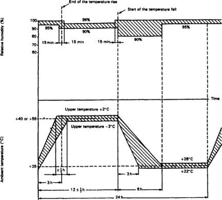
Fig. 4.4 Variant 2 (reproduced from the equivalent standard BS 7527 Section 2.1:1991 by kind permission of the BSI)
The test comprises one or more temperature cycles in which the relative humidity is maintained at a high level (e.g. 95%). The severity of the test is determined by the upper temperature limit of the cycle and the number of cycles that a specimen is subjected to.
Further information on the application of damp heat tests including a comparison of steady state and cyclic tests can be found in IEC 68.2.28.
4.4.4 Composite temperature/humidity cyclic test (IEC 68.2.38 Test Z/AD)

4.4.4.1 Introduction
This standard deals with the deteriorative effects caused by heat, cold and water vapour on electronic equipment.
4.4.4.2 Purpose of this test
The purpose of this test is to determine, in an accelerated manner, the resistance of specimens to the deteriorative effects of high temperature, high humidity and cold conditions.
4.4.4.3 General
For non-operational tests the specimen is introduced into the chamber in an unpacked, switched off, ‘ready to use’ state in its normal position or as otherwise specified.
When operational tests are required, the specimen has to be switched on or be electrically loaded.
4.4.4.4 Test conditions
This is quite a brutal test as equipment is exposed, first to high relative humidity (which will produce an entry of moisture through ‘breathing’, into partially sealed containers) followed by low temperatures and then (as an option) subzero freezing in order to determine the effects of periodic icing (see Figures 4.5. and 4.6).
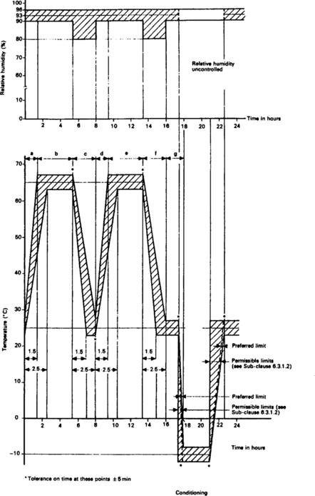
Fig. 4.5 Exposure to humidity followed by exposure to cold (reproduced from BS 7527 Section 2.1:1991 by kind permission of BSI)

Fig. 4.6 Exposure to humidity not followed by exposure to cold (reproduced from BS 7527: Section 2.1:1991 by kind permission of BSI)
4.4.5 Damp heat steady state test – primarily for equipment (IEC 68.2.56 Test Cb)

4.4.5.1 Introduction
This test is mainly used to determine the ability of an item of equipment to withstand high humidity conditions where condensation is absent.
4.4.5.2 Purpose of this test
The purpose of this test is to observe the effects of high humidity at constant temperature, on equipment over a prescribed period.
4.4.5.3 General
This test is particularly applicable to large equipment or equipment having complex interconnections and normally the test equipment is external to the test chamber.
The test can be applied to both heat dissipating and non-heat dissipating equipment. When testing heat dissipating specimens the test procedure ensures a good simulation of free air conditions and takes account of the effects of the specimen self-heating and the environment in the immediate vicinity of the specimen.
The test procedure is designed in such a way that condensation should not occur on the specimen, except in the case of active cooling devices which have a temperature below the dew point of the test atmosphere.
4.4.6 Climatic sequence test (IEC 68.2.61 Test Z/ABDM)
4.4.6.1 Introduction
This test deals with a range of environmental conditions to which equipment may be subjected in any combination.
4.4.6.2 Purpose of this test
The purpose of this test is to determine the suitability of specimens (primarily components) when subjected to environmental conditions consisting of a sequence of temperature, humidity and, where required, low air pressure environmental stresses.
4.4.6.3 General
This test is frequently specified to follow other tests involving mechanical stress (e.g. tests for robustness of terminations, solderability, shock and vibration) as a means of determining whether the sealing of a specimen has been damaged.
4.4.6.4 Test conditions
The test describes three types of composite test methods for determining the suitability of a specimen to a ‘climatic sequence’ of tests.
Test method one is preferred (see Figure 4.7) and contains five steps of which one (low atmospheric temperature) is optional.

Fig. 4.7 Diagrammatic representation of the progress of the climatic sequence (reproduced from the equivalent standard BS 2011 Section 2.1:1983 by kind permission of the BSI)
During this test the specimen is first exposed to a high temperature and then to a cycle of damp heat. This is immediately followed by a low temperature test so that any moisture which has entered, either the specimen or surface cracks in its seals, will be frozen and cause further damage. A low pressure test (optional) is then followed by further exposure to cyclic damp heat.
If required the severity of the test can be increased by completing a low temperature test in between each of the five final damp heat cycles.
4.4.6.5 Other Standards
| IEC 68.2.39 | Environmental testing procedures – Test Z/AMD: Combined sequential cold, low air pressure and damp heat test |
IEC 68.2.39 provides details of a combined sequential cold, low air pressure and damp heat test which may also be used for evaluating samples. This test is primarily intended for components and equipment used in aircraft and for high altitude applications.