Chapter 10 Design and Deploy High Availability for Exchange 2007
In This Chapter
![]() Choose a High Availability Solution
Choose a High Availability Solution
![]() Enable Local Continuous Replication
Enable Local Continuous Replication
![]() Configure Cluster Continuous Replication
Configure Cluster Continuous Replication
![]() Implement Standby Continuous Replication (SCR)
Implement Standby Continuous Replication (SCR)
![]() Design Hub Transport High Availability
Design Hub Transport High Availability
![]() Design Edge Transport and Unified Messaging High Availability
Design Edge Transport and Unified Messaging High Availability
Solution: The concept of high availability is nothing new. For many years, network administrators, realizing the possibility that a system can fail on any number of levels, have attempted to mitigate that failure by providing redundancy of system features (such as multiple disks, power supplies, and so on) and, in the most extreme of cases, disaster recovery methods. The goal is to make your systems fault tolerant, and failing in that, to make your systems quickly recoverable in a disaster-like circumstance.
High availability comes into play as a term in the Exchange world in absolute measurements of uptime that you strive for or offer to others when implementing a strategy. Uptime is more than the time the system is literally running; it implies access by a user. If a user cannot access the system (in this case, send or retrieve email), it doesn’t matter if it is running. It is not available.
Although there are third-party solutions by a variety of vendors that are worth investigating, Microsoft offers four different solutions: Local Continuous Replication (LCR), Cluster Continuous Replication (CCR), Standby Continuous Replication (SCR) and Single Copy Clusters (SCC). Different techniques are used; for example, clustering might be required. Notice, however, that in three of the solutions, the term continuous replication is used. This involves the use of a technology that is called log shipping and replay. This section explains how that works.
Recall from Chapter 1. “Introduction to Exchange 2007 SP1,” that we reviewed storage architecture and the use of storage groups, databases, and transaction logs. With continuous replication, your database is copied once. Then all log files that are created are shipped to the secondary copy and replayed into the duplicate database. In the event of a failure (be it disk or system, depending on the form of continuous replication high availability you’ve chosen), the secondary copy is ready to step in and take over.
Each flavor of high availability is a little different. Let’s look at each one.
NOTE You might recall with Exchange 2003 that the transaction logs were 5MB in size, but they have been reduced to 1MB. One of the reasons for this change is that smaller logs can be transported faster and leave less data lost if there is a problem before a log can be shipped over and replayed.
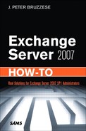
Often called the poor man’s cluster, LCR enables you to simply place another disk in a server and have the data mirror over using continuous replication (with transaction log shipping and the replay technology we discussed earlier), as shown in Figure 10.1.
The positive side is that this is the cheapest solution you can implement, requiring only an additional drive (or drives), and you can perform volume shadow copies off the passive side of the data if you like. With SP1 there is also a transport dumpster solution on the HT server that allows you to recover mail that might otherwise be considered lost when the disk fails.
The negative side is that you aren’t running cluster services, which means you have to manually switch from one disk to the other if a failure occurs. The time between when the first disk fails over to when you manually switch to the second disk is unavailable time for the server. The other negative is that there are issues that can take place with the system itself (such as power supply, motherboard, and network connection) that can hinder the availability of an LCR solution.
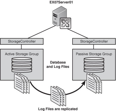
CCR works with the same technology in that it copies the transaction logs and replays them, but it uses cluster services from within your servers to provide an automatic failover solution. This provides more than automation; it also allows for a server and disk redundancy (whereas you saw that LCR only provides disk redundancy) as you can see in Figure 10.2. You also have the same ability to perform a volume shadow copy off the passive copy of the data.
In addition, there are features in place to ensure that even data that might not be synchronized between the active and passive sides to the cluster can be retrieved from the Hub Transport servers transport dumpster, which retains email passing through the server for a period of time.
On the negative side, implementing CCR requires a knowledge of clustering services as well as the additional hardware and software necessary to implement it properly.
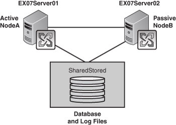
SCR is a solution that was introduced with SP1, so it brings a fresh look at continuous replication, where the concept is the same as LCR, log shipping, and replay. However, rather than going from disk to disk, it is from server to server. This doesn’t require cluster services, but it does provide the server and disk redundancy that you get from CCR, as you can see in Figure 10.3.

Where the technology can become a bit intriguing is if used in conjunction with other solutions. For example, you can use SCR to replicate a storage group from a CCR or SCC cluster over to a remote location if you like. Another positive feature is the built-in delay for replay activity (which is wonderful if you want to prepare your organization for database corruption scenarios where the delay could prevent the corruption from making its way to the SCR copy).
From a negative angle, you need additional hardware with software costs and you can manage SCR only from the Exchange Management Shell (EMS). The lack of cluster services means the automation process is out of the picture, so you have to manually failover from the active to the passive database, which explains why you might use SCR in conjunction with another form of cluster high availability for that automatic rollover in case of failure.
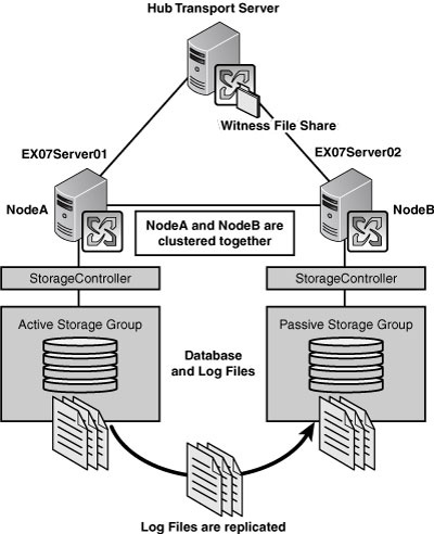
For those who remember the Exchange 2003 high availability options with shared storage, you will see that this is familiar. With SCC, you cluster two servers together where they have the same shared storage between them, as you can see in Figure 10.4. The positive side here is that you have automatic failover in the event of a server failure. The negative side is that the data has no high availability solution in place for your SAN (although, most likely your SAN is already prepared with some form of RAID solution in place).
The choices depend on a few simple factors. One is the size of your organization. If you have a small environment with a single Exchange server, it would hardly seem necessary for you to purchase a secondary server, upgrade everything to Enterprise Edition Windows Server software, cluster the two systems, and work out a CCR implementation. You might do well with LCR or perhaps, depending on your environment, with SCR.
![]() If you have a remnant from the SAN/NAS days of shared storage that you want to keep using, you might consider SCC.
If you have a remnant from the SAN/NAS days of shared storage that you want to keep using, you might consider SCC.
![]() If you have a need to ensure automatic failover and you do not have shared storage, CCR is a logical solution for you.
If you have a need to ensure automatic failover and you do not have shared storage, CCR is a logical solution for you.
![]() If you need to provide multiple levels of redundancy, you might consider a CCR deployment with a SCR failover from one CCR cluster to another.
If you need to provide multiple levels of redundancy, you might consider a CCR deployment with a SCR failover from one CCR cluster to another.
Cost, need, organizational size, and level of complexity are all factors to consider. However, the percentage of availability you wish to provide also comes into play. If you are working with a small business, there are times when the server doesn’t have to be online. For example, maybe everyone leaves for the weekend and you can perform maintenance during those periods. However, if you are setting up a hosted Exchange environment for a huge datacenter, not only is 100% availability a must, but you might decide to look into a third-party solution to help provide it for you.
In the meantime, let’s take a step back and begin working on how you would set up each of these solutions.
Solution: Remember, to implement LCR you can only have one database per storage group. You want to make sure you certainly have sufficient disk space for your LCR copy. You can implement LCR in one of two ways—either during the creation of the storage group or afterward.
If the storage group already exists, perform the following steps:
1. Open the Exchange Management Console (EMC).
2. From the Navigation Tree, expand the Server Configuration work center and click Mailbox.
3. From the Results pane, choose the server that has the storage group on which you want to enable LCR.
4. Select the storage group on which you want to enable LCR. (Note: If you select a storage group with more than one database, you will not even see the option to enable LCR.)
5. From the Actions pane, select Enable Local Continuous Replication to open the wizard.
6. On the Introduction screen, confirm the storage group name and database name, and click Next.
7. On the Set Paths screen, you are shown the default paths, but these are generally to a local disk. You might allow this for testing purposes, but it defeats the purpose of LCR. You want to relocate those to a separate disk. Click the Browse buttons to relocate those paths to a new disk. Then click Next.
8. You are shown the passive location of the database file (shown in Figure 10.5). Click Browse to alter this location as well. Then click Next.
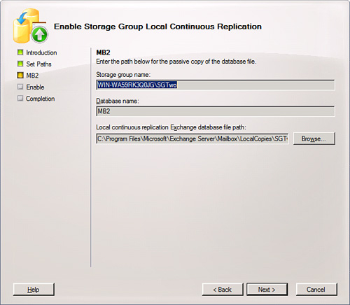
9. You are shown a configuration summary of both actions: making a copy of the database and making copies of the log and system files. Keep in mind that the database is copied once. The way it is kept up to date is through transaction logging and replaying into the database on the passive side. After you confirm your settings, click Enable.
10. When complete, click Finish.
What happens next is a process called seeding, where your database is created in the passive disk and this is the creation of the starting point for your LCR version. After LCR is complete, you should notice a change in the icon next to your storage group. Some new options in the Actions pane for your storage group are to disable or suspend the LCR.
NOTE An easy way to confirm the functionality of LCR is to open the folder that holds the active location of your transaction log files. Then open the location of the passive copy of the logs. Through your Outlook client or Outlook Web Access, send a few messages through to mailboxes within that database. You should see the transaction logs grow on the active side and then shortly afterward you should see the passive copy increase, too. This provides a visual confirmation that LCR is working just fine.
PS NOTE The cmdlets through the Exchange Management Shell used to enable LCR on an existing storage group include two separate commands:
Enable-DatabaseCopy -Identity <Server><StorageGroup><Database> -
CopyEDBFilePath:<FullPathIncludingDatabaseFileName>
Enable-StorageGroupCopy -Identity <Server><StorageGroup> -
CopyLogFolderPath:<FullPath> -CopySystemFolderPath:<FullPath>
You recall when we created storage groups in Chapter 4, “Manage Storage and Databases,” that we didn’t address the checkbox for creating LCR. We need to revisit the process:
1. Open the EMC.
2. From the Navigation Tree, expand the Server Configuration work center and click Mailbox.
3. From the Results pane, choose the server where you want to create the Storage Group.
4. From the Actions pane, choose New Storage Group to open the wizard.
5. Using the Browse buttons, you can determine the location of the log and system files.
6. Select the checkbox Enable Local Continuous Replication For This Storage Group, and then use the Browse buttons to determine the location of the passive log and system files for replication.
7. When you are ready, click New and then Finish.
This completes the first part for creating a storage group that is LCR-enabled, but the next part is the database. When you create the database for the storage group, you need to browse for the location of the active database and for the location of the replicated database. When you are ready, click New and then Finish.
To see how your LCR performs, there is a tab in the properties of the storage group that shows you information regarding your LCR status. To view that information, perform the following:
1. Open the EMC.
2. From the Navigation Tree, expand the Server Configuration work center and click Mailbox.
3. From the Results pane, choose the server where you want to create the storage group.
4. From the Work pane, select the storage group for which you want to see the properties.
5. From the Actions pane, select Properties.
6. Select the Local Continuous Replication tab, shown in Figure 10.6.
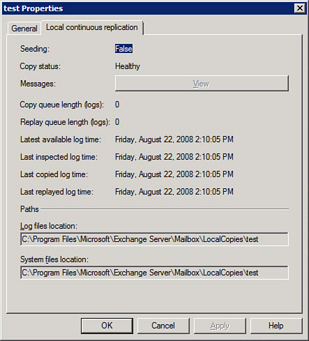
7. Note the Copy Status is Healthy. If there is a problem, you might see Broken, Disabled, or Failed.
8. Assuming everything is healthy, you can click OK to close the dialog.
NOTE In the event you do notice a problem with your LCR replication, you can check to make sure the paths are all correct and accessible. If you find a problem, fix it and then suspend and restart LCR on the storage group. You might have a problem with a missing transaction log, which sometimes causes LCR to halt. Try the Update-StorageGroupCopy cmdlet to reseed your LCR. However, if you need to find other problems, the following TechNet article will assist you: http://technet.microsoft.com/en-us/library/aa996038.aspx.
Unfortunately, there are times when your active disk might fail. With LCR you have to manually intervene, but you can recover your working environment quickly depending on how fast you are notified and how rapidly you can respond to the failed disk.
The process requires three actions:
![]() Dismount the database.
Dismount the database.
![]() Alter the pointer for the database to point at the passive copy. Note: If the disk itself is not harmed but the database has become corrupt, you don’t have the change the pointers; simply move the database over to the production location and remount. If the disk went bad, you need to alter the pointers.
Alter the pointer for the database to point at the passive copy. Note: If the disk itself is not harmed but the database has become corrupt, you don’t have the change the pointers; simply move the database over to the production location and remount. If the disk went bad, you need to alter the pointers.
![]() Remount the database.
Remount the database.
To perform these actions, do the following:
1. Open the EMC.
2. From the Navigation Tree, expand the Server Configuration work center and click Mailbox.
3. From the Results pane, choose the server where the disk has failed.
4. From the Work pane, select the database, and choose Dismount from the Actions pane.
5. You can activate the copy that has been moved to the production location or activate the copy that is in the passive location depending on whether the disk died or the database simply corrupted. In either case, you will use the Restore-StorageGroupCopy cmdlet.
![]() If you want to activate the copy that has been moved to the production storage group, so the paths are unchanged, type
If you want to activate the copy that has been moved to the production storage group, so the paths are unchanged, type
Restore-StorageGroupCopy -Identity:<Server>
<StorageGroupName>
![]() If you want to activate the copy that is on the passive disk, so you will have the indicate the alteration of the production path, type
If you want to activate the copy that is on the passive disk, so you will have the indicate the alteration of the production path, type
Restore-StorageGroupCopy -Identity:<Server>
<StorageGroupName> -ReplaceLocations:$true
6. Select the database and choose to mount it from the Actions pane.
Keep in mind that LCR is no longer functioning on the storage group because you just disabled it by switching to your passive copy. You have to put in a new disk or simply configure LCR again to use the locations on different disks that you have prepared in your system.
Solution: CCR uses the same continuous replication technology that we see in LCR; however, it performs the failover automatically. It does this through cluster services that we have to install and configure. Then we need to install the active and passive mailbox roles. Essentially, this is the process involved with CCR:
![]() First, begin with two systems with either Server 2003 or 2008 installed on them. You must use the Enterprise Edition because cluster services work only on that edition of Server. Ensure that neither has Exchange 2007 Server installed. We are installing only the Mailbox roles (active and passive) on these machines. The systems will need to have a public and private network connection. The public connection is for users to send and retrieve email to each other through the servers. The private connection is for the two servers to be able to speak to one another through a heartbeat that lets the active and passive roles know the other is alive and well.
First, begin with two systems with either Server 2003 or 2008 installed on them. You must use the Enterprise Edition because cluster services work only on that edition of Server. Ensure that neither has Exchange 2007 Server installed. We are installing only the Mailbox roles (active and passive) on these machines. The systems will need to have a public and private network connection. The public connection is for users to send and retrieve email to each other through the servers. The private connection is for the two servers to be able to speak to one another through a heartbeat that lets the active and passive roles know the other is alive and well.
![]() When configuring the cluster, we will set up a two-node cluster. This might seem like a problem because with only two nodes, there is the chance for a problem called split brain syndrome. That is a situation where, for example, the passive system believes the active has gone down and decides to promote itself as the active system. However, let’s say the active didn’t go down—the cable connection is disconnected or something simple. Now you have two active servers at one time. That is a problem. To resolve this problem, many clusters use three or more servers. What was needed was a new form of quorum model, and the Exchange Team decided to use a Majority Node Set (MNS) quorum.
When configuring the cluster, we will set up a two-node cluster. This might seem like a problem because with only two nodes, there is the chance for a problem called split brain syndrome. That is a situation where, for example, the passive system believes the active has gone down and decides to promote itself as the active system. However, let’s say the active didn’t go down—the cable connection is disconnected or something simple. Now you have two active servers at one time. That is a problem. To resolve this problem, many clusters use three or more servers. What was needed was a new form of quorum model, and the Exchange Team decided to use a Majority Node Set (MNS) quorum.
![]() A quorum is like a referee. The way the MNS quorum works is off a file share that you can set up anywhere. However, it is recommended you set it up on a Hub Transport server. The file share acts as a witness between the two servers because if their heartbeat seems to fail, they can connect to the file share and confirm that the other server really is down before the passive takes over as the active.
A quorum is like a referee. The way the MNS quorum works is off a file share that you can set up anywhere. However, it is recommended you set it up on a Hub Transport server. The file share acts as a witness between the two servers because if their heartbeat seems to fail, they can connect to the file share and confirm that the other server really is down before the passive takes over as the active.
![]() One aspect of this entire procedure is called the transport dumpster, which is enabled on the Hub Transport servers when you install CCR. This helps ensure less mail is lost in the event of a failover. The way it works is that if the active node fails and the passive takes over, in the brief time span in which this occurs, data can be lost or in transit. The most recent mail might be in logs and might not have been shipped over and replayed in time. So, the Hub Transport servers maintain a queue of recently delivered mail in an area called the transport dumpster. When the passive takes over, it checks the Hub Transport servers for any items that it doesn’t have. Duplicates are weeded out, but anything the passive doesn’t have will be added. Note: With SP1, this feature exists for use with LCR, as well.
One aspect of this entire procedure is called the transport dumpster, which is enabled on the Hub Transport servers when you install CCR. This helps ensure less mail is lost in the event of a failover. The way it works is that if the active node fails and the passive takes over, in the brief time span in which this occurs, data can be lost or in transit. The most recent mail might be in logs and might not have been shipped over and replayed in time. So, the Hub Transport servers maintain a queue of recently delivered mail in an area called the transport dumpster. When the passive takes over, it checks the Hub Transport servers for any items that it doesn’t have. Duplicates are weeded out, but anything the passive doesn’t have will be added. Note: With SP1, this feature exists for use with LCR, as well.
Although LCR remains the same for both Server 2003 and Server 2008, there are some slight changes between the two for CCR. The reason is that cluster services receive a slight makeover (and a new name—Failover Clustering) in Server 2008. Let’s look into configuring both of these, starting with Server 2003.
Keep in mind that in some of these steps, you are considered capable of going forward and carrying out the instruction without a step-by-step aspect to it because it assumes basic networking knowledge. Other parts walk you through step by step because cluster services is not something every administrator has the chance to work with.
So to configure cluster services, perform the following:
1. You should create a separate account for the cluster services and make that account a member of the Exchange Server Administrators group or Exchange Organization Administrators group. The account should also be put in the local Administrators group for each node.
2. On a Hub Transport server in the same site as the clustered nodes, create a folder and give it any name you like (within reason, such as MNSCluster) and share that folder out on the network. Set the share permissions to Full Control for the cluster administrators account that you created.
3. Configure your network adapters. As mentioned previously, you should have a public and private connection. It’s recommended, for the sake of organization, that you properly label these in your Network Connections so you know which one you are looking at quickly. You want to have static addresses for both the public and private networks. The private network needs to use a different IP addressing scheme and Microsoft recommends the addresses 10.10.10.x for both (you can go with 10.10.10.10 and 10.10.10.11 for the active and passive private connections). Check your binding order on the network adapters, too (on the Adapters and Bindings tab of the Advanced Settings for your connection) and put the Public connection to the top of the binding order.
4. Before proceeding, on both nodes of the cluster you want to download and install KB 921181. This is an update fix that you want to ensure is installed on these servers. It allows them, as clusters, to use the file share witness we created earlier and to configure the heartbeats feature. You should read the KB and then install the hotfix.
After your systems are ready, you can perform the following on the active node of the two-node cluster:
1. Select Start, Administrative Tools, and then Cluster Administrator to open the wizard (or from the command line, type cluster /create/wizard).
2. From the drop-down box, select Create New Cluster and then OK.
3. Read the first page of the wizard, and then click Next.
4. On the Cluster Name and Domain screen, the Domain is already filled in for you, but you have to provide a unique name for the cluster. You might try a name like E2K7Cluster or something similar; it is your choice. Then click Next.
5. You are asked to type in the name of the server that will be the first node of the cluster. You can name your servers something logical like Node1, Node2, or something similar. Then click Next.
6. The wizard will now analyze the configuration. When it completes, note any warnings and click Next.
7. You are asked for the IP address that the cluster management tools will use to connect up to the cluster. This is a public IP address, not a private one, and you want to ensure it is a unique address on the system. Then click Next.
8. You are asked for the Cluster Service Account at this point, and if you followed the instructions earlier, you should have an account prepared for handling your cluster services already in place. Fill in that information and click Next.
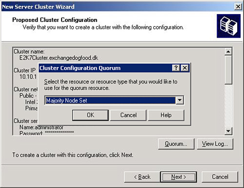
9. Here you are shown the Proposed Cluster Configuration, and here is where you need to choose the type of quorum. Select the Quorum option, shown in Figure 10.7. Then select the down arrow, choose Majority Node Set, and click OK.
10. From the Creating the Cluster screen the first node is going to be established. Click Next.
11. At the completion screen, you can view the log of the entire procedure. When you are ready, click Finish.
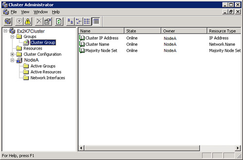
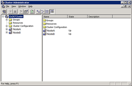
To confirm the first node of your cluster is up and running, open up Cluster Administrator and expand the name of your cluster. Then expand Groups and Cluster Groups and you will hopefully see that your cluster is online, as you can see in Figure 10.8.
Having a cluster with one node is not an effective high-availability solution. So, we need to add the second node. To do this, perform the following:
1. Open Cluster Administrator from your cluster tools.
2. Right-click the primary node server name, select New, and then Node. This will start the Add Nodes Wizard. Click Next.
3. Type the name of your second node and click Add. Remember, we are adding only two nodes for our CCR cluster.
4. The wizard will analyze and confirm that everything is in place to form the cluster. When complete, click Next.
5. You are asked for the cluster service account again, which you should have in place already. Add that information, and click Next.
6. The Proposed Cluster Configuration page will display and you can confirm the setting choices you made. If everything is correct, click Next.
7. After the cluster is complete, click Finish.
To confirm that your two-node cluster is up and running, open the Cluster Administrator and you should see the cluster. You should be able to see two servers (your Node1 or NodeA and your Node2 or NodeB). You should see in the State column that they are both Up, as shown in Figure 10.9.
NOTE Another method to confirm that the cluster is up and running is to go to a command prompt and type cluster group or cluster node, and you will see a response regarding your cluster or nodes and the status.
After your cluster is set, you need to establish the file share you configured to be your MNS quorum witness. This works if you installed the hotfix and if the share is correct. To do this you need to go to a command line and type
Cluster res “Majority Node Set” /priv MNSFileShare=\servernamesharename
At this point, you are ready to perform the installation of Exchange 2007 for the Mailbox server roles for the active and passive side.
The installation begins like a typical installation:
1. Insert the DVD or mount the ISO for the Installation screen to display. Select the link from Step 4 to begin the Installation Wizard.
2. You will be taken to the Introduction screen. Select Next.
3. You are taken to the License Agreement screen. Choose I Accept the Terms in the License Agreement, and select Next.
4. You are taken to the Error Reporting screen. Make your choice before selecting Next.
5. This brings you to the Installation Type screen, where you can choose either a typical or custom Exchange Server installation. In this case, select Custom Exchange Server Installation.
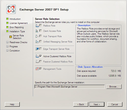
6. Under Server Role Selection, select Active Clustered Mailbox Role, as you can see in Figure 10.10. The Management Tools are selected by default. Select your options and choose Next.
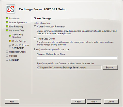
7. Under Cluster Settings, shown in Figure 10.11, you want to choose the Cluster Continuous Replication option. You also need to provide the Clustered Mailbox Server Name (CMS). This is the name your Outlook clients use to connect to the server. You can alter the path to the Clustered Mailbox Server database files if you like by choosing the Browse button. When you are ready, click Next.
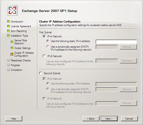
8. On the Cluster IP Address Configuration screen, you have the ability to define more than one subnet, as you can see in Figure 10.12. You can determine the use of IPv4, IPv6, or both. (Note that it is possible to use a DHCP-assigned address, but it is not recommended.) When complete, click Next.
9. The Readiness Checks screen checks to make sure your system is ready for the installation of the server options you’ve chosen. After you are clear to move forward, choose Install.
10. The Progress screen walks you through the process of the actual installation. When complete, it takes you to the Completion screen and shows you what has been installed successfully. Click Finish.
After you install the active side, the next step is to install the Passive Clustered Mailbox role. Follow the same steps but choose the passive mailbox.
Some people might wonder whether it is better to use Server 2008 over Server 2003. This is logically true. There are enhancements with the clustering services, now called Failover Clustering, that can assist you in creating a more stable and secure cluster for CCR. Some of the new features are multiple subnets, support for geo-clusters, failover across two subnets, and support for IPv4 and IPv6.
In addition, there is a new Failover Cluster Management console based upon the MMC 3.0 changes, shown in Figure 10.13.
There is a new quorum model that allows four different hybrids from which to choose:
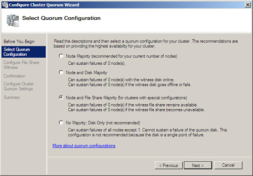
![]() Node Majority—For use with clusters with an odd number of nodes (for use with clusters of three or more), which is really only helpful in an SCC situation (even though you can use it for CCR, it isn’t practical because you can use the file share witness and not waste an entire system acting as a node).
Node Majority—For use with clusters with an odd number of nodes (for use with clusters of three or more), which is really only helpful in an SCC situation (even though you can use it for CCR, it isn’t practical because you can use the file share witness and not waste an entire system acting as a node).
![]() Node and Disk Majority—For clusters with an even number of nodes. Each node gets a vote, as does the witness disk, which might reside on shared storage.
Node and Disk Majority—For clusters with an even number of nodes. Each node gets a vote, as does the witness disk, which might reside on shared storage.
![]() Node and File Share Majority—For clusters with special configurations, which is the equivalent of the Majority Node Set that we have with Server 2003, and the one we use for CCR.
Node and File Share Majority—For clusters with special configurations, which is the equivalent of the Majority Node Set that we have with Server 2003, and the one we use for CCR.
![]() No Majority: Disk Only—This is what they might call traditional shared quorum clustering. It can sustain a failure of all the nodes except one. It cannot sustain a failure of the quorum disk. (Note that although this option is available, the instructions clearly say, “This configuration is not recommended because the disk is a single point of failure.”)
No Majority: Disk Only—This is what they might call traditional shared quorum clustering. It can sustain a failure of all the nodes except one. It cannot sustain a failure of the quorum disk. (Note that although this option is available, the instructions clearly say, “This configuration is not recommended because the disk is a single point of failure.”)
To perform the preparation process for the CCR, setup on Server 2008 requires some of the same steps for Server 2003.
To configure cluster services, perform the following:
1. You should create a separate account for the cluster services and make that account a member of the Exchange Server Administrators group or Exchange Organization Administrators group. The account should also be put in the local Administrators group for each node.
2. On a Hub Transport server in the same site as the clustered nodes, create a folder and give it any name you like (within reason, such as MNSCluster) and share that folder on the network. Set the share permissions to Full Control for the cluster administrator’s account that you created.
3. Configure your network adapters. You should have a public and private connection. It’s recommended, for the sake of organization, that you properly label these in your Network Connections so that you know which one you are looking at quickly. You want to have static addresses for both the public and private networks. The private network needs to use a different IP addressing scheme, and Microsoft recommends the addresses 10.10.10.x for both (you can go with 10.10.10.10 and 10.10.10.11 for the active and passive private connections). Check your binding order on the network adapters, too (on the Adapters and Bindings tab of the Advanced Settings for your connection) and put the Public connection to the top of the binding order. Note that IPv6 is installed by default with Server 2008, and you are welcome to work that, too. IPv6 is the way of the future.
4. On a Server 2008 system, you have to add the Failover Clustering feature from the Add Features Wizard through Server Manager. You want to ensure you have IIS and PowerShell installed. The active and passive servers still require all the same requirements for Exchange that they do for a typical installation.
After you have the prerequisites in place, you need to proceed with the creation of the failover. To do this, perform the following:
1. On the active server click Start, Administrative Tools, and then select Failover Cluster Management.
2. This will launch the Failover Cluster Management console. Under Management you will see a link to Create a Cluster. Select that link.
3. The Create Cluster Wizard will launch. On the Before You Begin screen, you are given information about the wizard and to ensure you are prepared to move forward. When you have read the information, click Next.
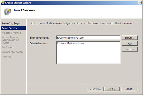
4. On the Select Servers screen, shown in Figure 10.14, you are asked to locate the servers you want for the cluster. In this case, you should have two servers selected. Then click Next.
5. You are taken to the Access Point for Administering the Cluster screen. You are asked to provide a cluster name (which is not the name of the cluster that will be accessed by Outlook clients; that name is configured when you perform the install of the active and passive mailbox nodes). You are also asked to provide an IP address for administrative connectivity. After these are set, click Next.
6. From the Confirmation screen, you can confirm the settings you have chosen, and click Next.
7. You are able to watch the process as the new cluster is created. Then you are taken to the Summary pane, where you can select View Report for a detailed report of the process, and click Finish.
Now that you have the failover cluster in place, certain aspects still need to be configured. For example, you need to select which interface is public and which is private (that is, for the heartbeat that lets each side of the node know that the other is alive and well).
To begin, open the Failover Cluster Management tool, expand Networks, and then open the properties page of the public network interface, as you can see in Figure 10.15. You might want to make changes to the name to make it easily identifiable as the public side. Then make sure you select the radio button, Allow the Cluster to Use This Network, and the checkbox, Allow Clients to Connect Through This Network.
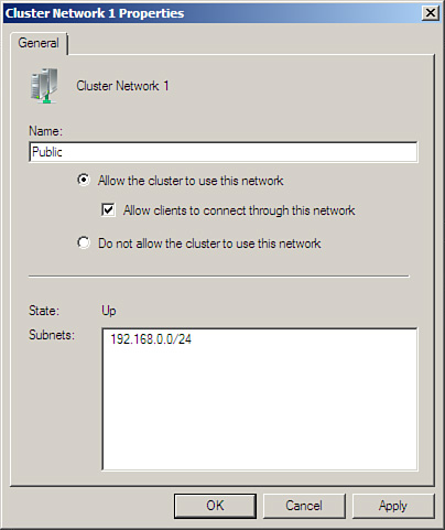
Next, open the private network interface and do the same, although deselect the checkbox to allow clients to connect through this network.
Configuring the File Share Majority quorum is easier in Server 2008 because there is a wizard now. You still need to create the file share as we noted earlier, typically on a Hub Transport server. Make sure the cluster account receives the proper Full Control permissions over the share. With the share created, you can open the wizard to configure the quorum to use that model and to use the UNC for the share. Perform the following:
1. Open the Failover Cluster Manager on one of the two nodes.
2. From the Actions pane, select More Actions, and you will see the Configure Cluster Quorum settings. Click this to open the wizard.
3. To begin with, you are shown the Before You Begin screen, where you can read a bit about configuration of the quorum. When you are ready, click Next.
4. You are taken to the Select Quorum Configuration screen shown in Figure 10.16, which has the four options we discussed earlier. The third one, Node and File Share Majority (for clusters with special configuration), is the one we want for the CCR cluster. Select that radio button and click Next.
5. Under the Configure File Share Witness screen, you are asked to provide the UNC path (or Shared Folder Path) to the folder you shared out. Type that in, or Browse for the location, and click Next.
6. The Confirmation screen simply asks you to verify the cluster quorum. Click Next.
7. After the configuration completes, click Finish.
The next part of the process is to validate the cluster functions properly. To do this, perform the following:
1. Open the Failover Cluster Manager on one of the two nodes.
2. From the Management section, click the Validate a Configuration link to open the wizard.
3. The Before You Begin screen provides information on the validation process; you can read through this and click Next.
4. You are asked to select a set of servers to validate. Choose the two servers in your cluster and click Next.
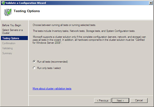
5. You are taken to the Testing Options screen, shown in Figure 10.17. You are given the option to run all tests or run selected tests. It’s your decision, but perhaps the first time you should run all tests (which is recommended) and click Next.
6. You are taken to the Confirmation screen, and you can see the list of tests that will be performed on your systems. When ready, click Next.
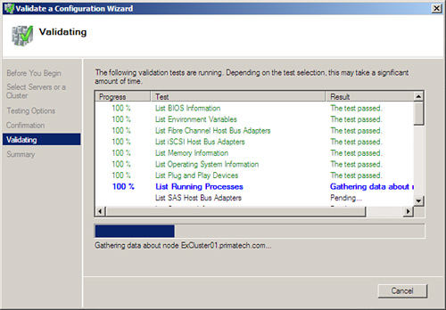
7. The Validating screen displays. You see your cluster as it is put through one test after another, and you can see the results, shown in Figure 10.18.
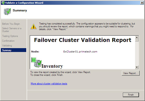
8. After completion, you are taken to the summary page, where you can scroll through and see a report of the process (shown in Figure 10.19). You can also click View Report to see a detailed report of the testing. When you are done, click Finish.
At this point, you are ready to perform the installation of Exchange 2007 for the Mailbox server roles for the active and passive side.
The installation begins like a typical installation:
1. Insert the DVD or mount the ISO for the Installation screen to display. Select the link from Step 4 to begin the Installation Wizard.
2. You are taken to the Introduction screen. Select Next.
3. You are taken to the License Agreement screen. Choose I Accept the Terms in the License Agreement, and select Next.
4. You are taken to the Error Reporting screen. Make your choice before selecting Next.
5. This brings you to the Installation Type screen, where you can choose either a typical or custom Exchange Server installation. In this case, select Custom Exchange Server Installation.
6. Under Server Role Selection, select Active Clustered Mailbox Role. The Management Tools are selected by default. Select your options and choose Next.
7. Under Cluster Settings, choose the Cluster Continuous Replication option. You also need to provide the CMS. Your Outlook clients use this name to connect to the server. You can alter the path to the Clustered Mailbox Server database files if you like by choosing the Browse button. When you are ready, click Next.
8. On the Cluster IP Address Configuration screen, you have the ability to define more than one subnet. You can determine the use of IPv4, IPv6, or both. (Note that it is possible to use a DHCP assigned address, but it is not recommended.) When complete, click Next.
9. The Readiness Checks screen checks to make sure your system is ready for the installation of the server options you’ve chosen. After you are clear to move forward, choose Install.
10. The Progress screen walks you through the process of the actual installation. When complete, it takes you to the Completion screen and shows you what has been installed successfully. Click Finish.
After you have the active side installed, you next step is to install the Passive Clustered Mailbox role. Follow the same steps but choose the passive mailbox.
In the RTM of Exchange 2007, you could configure the transport dumpster through the EMS using the Set-TransportConfig cmdlet. However, in SP1 there is a GUI method now through the EMC.
The default configuration for the dumpster is to have the Maximum Size Per Storage Group (MB) option set at 18 and the Maximum Retention Time (Days) option set at 7. If you feel the need to alter this, you can. To do this, you go through the Organization Settings work center, click the Hub Transport node, and under the Global Settings tab you can view the properties of the Transport Settings. On the General tab (shown in Figure 10.20), you can make changes.
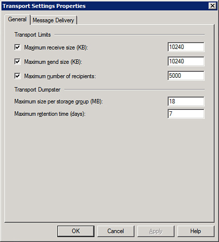
NOTE Microsoft recommends you set the maximum size to 1.5 times the size of the maximum messages allowed through your system. So, a size limit of 10MB would be a transport dumpster size of 15MB. Microsoft recommends seven days of retention time. So, overall, the defaults are probably fine depending on your maximum message size allowed.
With the RTM version of Exchange, we had to use the EMS to determine whether our CCR cluster was healthy, but now there are ways to check within the EMC. For example, much like with LCR, you can view the properties of the server, and there is now a Clustered Mailbox tab. This shows you if the cluster is online and which node is active.
If we view the properties of the storage group, we can see a new Cluster Continuous Replication tab and see whether our Copy status is healthy.
A new wizard in SP1 called the Manage Clustered Mailbox Server Wizard allows you to move the mailbox to another node, and stop or start the clustered mailbox server. This wizard can be located in the Actions pane if you select the CMS from the Server Configuration work center.
Solution: SCR provides a solution that we did not have with the RTM of Exchange and the initial clustered solutions of CCR and SCC—a combination of site resilience and high availability.
By site resilience, what we mean is under a 2003 cluster, both nodes had to be in the same subnet. There was still a way of placing each node in different locations or physical sites. However, they needed to be on the same network, and you might be using a virtual LAN to accomplish the illusion for the cluster.
However, with Server 2008 and Exchange 2007 SP1, we have new clustering abilities and site resilience added to the mix. We can now place our nodes in two different sites.
The simplest use of SCR is along the same lines of LCR, but across two different systems (not just two different disks). You can see how this can be taken to the next level, and you can place these systems in two different sites. However, SCR can do much more. It can create secondary copies of CCR and SCC sources. The source might be a cluster, but the target of the SCR configuration doesn’t have to be a clustered target. It can be a single mailbox server or a passive node waiting to spring into action.
Due to the complexity of SCR, we do not cover each possible scenario. Rather, we suggest that you research your specific needs and solutions online. However, we review the basic requirements and configuration options to get SCR up and running.
Some of the requirements for an SCR solution include the following:
![]() As with other implementations, there can only be one database per storage group.
As with other implementations, there can only be one database per storage group.
![]() Both the source (or active copy) and target (or passive copy) have to be in the same AD domain.
Both the source (or active copy) and target (or passive copy) have to be in the same AD domain.
![]() The source and target have to use the same OS. The target must have the Mailbox role installed (if a cluster, it must be a passive role).
The source and target have to use the same OS. The target must have the Mailbox role installed (if a cluster, it must be a passive role).
![]() Either the Enterprise or Standard Editions can be used for SCR.
Either the Enterprise or Standard Editions can be used for SCR.
![]() The database and storage group paths have to be the same for both the source and target.
The database and storage group paths have to be the same for both the source and target.
![]() SCR does not use cluster services—it uses the replication service to perform the continuous replication process.
SCR does not use cluster services—it uses the replication service to perform the continuous replication process.
![]() There is a 50-log lag between the source and target by default. There is also a 24-hour replay time that you can configure.
There is a 50-log lag between the source and target by default. There is also a 24-hour replay time that you can configure.
In our simple scenario, imagine we have two servers—Ex01 (our source) and Ex02 (our target)—and each has the typical installation with Hub Transport, CAS, and Mailbox roles. Both are running Server 2008, and they are both in the same AD domain.
To implement SCR in a simple scenario where you wish to have the database and log files under a storage group called SCR1 on one system replicated over to another system, perform the following:
Open the Exchange Management Shell and type the following command:
Enable-StorageGroupCopy -Identity SCR1 -StandbyMachine Ex02![]() -ReplayLagTime 0.0:4:0 -TruncationLagTime 0.0:5:0
-ReplayLagTime 0.0:4:0 -TruncationLagTime 0.0:5:0
What exactly did we type here?
Well, the -StandbyMachine is the location of the target system for the passive copy. The -ReplayLagTime is a predetermined amount of lag before replaying of the copied log files occurs. This is to prevent a corrupt database and logs from continuing. The format is days.hours:minutes:seconds, so we gave this a 4-minute delay (although the default time is 24 hours, with the maximum being 7 days). There is a predetermined 50-log limit by default, so that regardless of our settings, there is always a 50-log delay to prevent corruption of the passive database. Finally, we have the -TruncationLagTime where we specify the amount of time the replayed log files can sit before they are deleted from the target.
There are several ways of knowing that your SCR procedure worked. The first is to check the event viewer and look for Event ID 2114, which tells you that replication has begun.
You can also open an EMS shell and type Get-StorageGroupCopyStatus -StandbyMachine (target server name) and you will be shown if the status is healthy, if logs have replayed, and so on.
You can also perform the same test we did with LCR, which is to look at the source transaction log location and the target transaction log folder and see that copies are being made (taking into consideration that there is a delay built in).
NOTE Remember, there is no visual confirmation from the EMC that you have succeeded in your task of enabling SCR. If you look at the target server, you do not see anything different in the EMC regarding that server. Perhaps SP2 includes a more graphical implementation of SCR, but for now we need to use the EMS to perform a visual check of the target server to see whether something is replicating.
You may wonder: What if your source goes bad and you need to bring the SCR copy online? There are a few different options for activating SCR copies. In fact, Microsoft has an excellent article at http://technet.microsoft.com/en-us/library/bb691321.aspx.
Solution: Recall that SCC only provides you failover for your systems. The fault tolerance of your servers is going to have to be looked after by the appliance features itself, which no doubt are quite adequate.
Much of what you know already from the CCR information presented previously applies here. You need to configure a cluster and then perform the installation of the active and passive nodes. The only difference is that you choose SCC instead of CCR when performing the installation of the mailbox servers.
One of the biggest differences with SCC on a Server 2008 system is that you choose a different option for configuring your quorums. During the quorum configuration portion of the Configure Cluster Quorum Wizard, you want to choose Node and Disk Majority (recommended for your current number of nodes). Then on the Configure Storage Witness screen, you want to indicate the storage volume you want to use as the disk witness.
Solution: Installing additional Client Access servers provides multiple points for access, but not necessarily high availability. Remember, your CAS servers are responsible for OWA, ActiveSync, and several other solutions that require availability through well placed and uniquely configured CAS servers.
However, keep in mind that the majority of the services provided through a CAS server are handled through your IIS settings. Network Load Balancing (NLB) clusters provide high availability for IIS.
In the event you want higher availability for a CAS server, you can always use NLB. On the one hand, NLB distributes client requests across multiple servers, so that offsets some of the load. On the other hand, if one server goes down, the others continue. NLB is also provided for both the Standard and Enterprise versions of Server so you don’t need any special software to implement it.
Logically, there are some differences in how to configure NLB, depending on whether you are using Server 2003 or Server 2008. To enable NLB on your CAS server (running 2003), perform the following:
1. Create a record for the NLB cluster in your DNS Manager. To do this, click Start, Administrative Tools, and then DNS. Expand the Forward Lookup Zones container, right-click the zone for your AD, and click New Host (A). Type the name and IP address (within the same subnet as your two CAS servers) you want to use for the NLB cluster.
2. Your next step is to configure your network adapters. Each CAS server should have two adapters for the NLB cluster. One is Public and the other Private (or NLB). First, you might want to name the connections, so that you can easily locate the right one when you return to the servers. Then change the binding order so the Public connection comes first (which is done by going into Advanced Settings from the Network Connections dialog and under the Adapters and Bindings tab, making sure the Public connection is first).
3. To enable NLB on the first server, go to your NLB adapter and go into the properties. On the General tab, you can turn on Network Load Balancing and go into the properties.
4. Under Cluster Parameters, enter the IP address and subnet mask as well as the full internet name. These are the same settings we configured in DNS. Make sure the cluster operation mode is Unicast.
5. On the Host Parameters tab, input the IP and Subnet mask of the network adapter itself.
6. On the Port Rules tab (delete the default), configure the port range for those connections that you have coming in (HTTP, SSL, POP, IMAP) depending on the work of our CAS servers.
7. After you have the settings complete, you need to add the cluster IP address to the TCP/IP property page of the network adapter itself. To do this, go into the Advanced TCP/IP Settings off the adapter and add the IP address.
8. Adding the second CAS server to the mix is done using the Network Load Balancing Manager, which is opened from Administrative Tools.
9. To add the second server, select Cluster from the menu and then Add Host. Type the name of the second CAS server, and then click Connect. Select the cluster name and click Finish.
10. You are taken to the Host Parameters tab. Type the IP address and subnet mask of the adapter that is part of the NLB cluster. Then you see in the manager that the two servers are NLB-connected.
If you want to perform the same actions in Server 2008, consider the following:
1. In Server 2008, NLB is a feature you need to turn on in the Features. Open your Server Manager, and add the feature.
2. With Server 2008, you can go through your Network and Sharing Center and turn NLB on for the adapter you want to enable NLB clustering on; however, to configure it, you are told to go to the Network Load Balancing Manager, which is found under Administrative Tools.
3. After you open the Network Load Balancing Manager (after you have turned on NLB for your adapter), notice that you have the initial part set up, but it is Unconfigured in the Status. To fix this, select your connection (which might be 0.0.0.0) and go to the Cluster Properties. Here, you see familiar screens if you have done this before in Server 2003—Cluster IP Addresses, Cluster Parameters (shown in Figure 10.21), and Port Rules.

NOTE In the next section, we discuss the capability of the Hub Transport server role to automatically load balance when you have more than one in an Active Directory site. However, if you need to load balance (which is necessary under certain situations), configuration is the same as what we have here for the CAS server.
Solution: By default, Hub Transport servers are resilient. The Hub Transport role is registered in Active Directory; therefore, as you add more servers with the role, they are noted in the event of a failure. Load balancing within the site is automatically configured with however many Hub Transport servers you use.
The only time this isn’t the case is when the HT role is installed on the same server as the Mailbox role. This is logical because the Mailbox server will automatically use the local HT server.
Sometimes you might have a need to load balance your Hub Transport services. You wouldn’t do this for most scenarios; however, you might have an application that requires the relaying of messages. In the RTM version of Exchange, you might have considered a round-robin DNS or MX records, but with SP1, you have the capability to use a hardware or Windows-based NLB solution.
NOTE If you do need to use Windows NLB for your Hub Transport servers, the steps are pretty much the same as what we have for the CAS server to enable NLB between your servers. However, remember that NLB is not supported for load balancing your internal Hub Transport connections (which are handled automatically). You would seek only to use this solution on inbound SMTP connections from applications (perhaps a Microsoft Office SharePoint Server or a System Center Operations Manager solution) that submit messages to an Exchange organization through an SMTP relay (because the applications cannot log directly into a MAPI mailbox). These are unique scenarios, and we encourage you to research thoroughly your solution before load balancing your Hub Transport servers.
Solution: Unlike the Hub Transport server, which automatically load balances between them (due in part to Active Directory), the Edge Transport servers do not have this capability.
You can deploy multiple Edge Transport servers and then use DNS MX (Mail Exchanger) records to ensure the Edge Transport servers have the load balancing aspect, and at the same time, if one fails, there is another to keep messaging flowing in and out of your organization.
In the case of Unified Messaging servers, the concept is similar. Deploy multiple servers where two or more are in the same dial plan. For load balancing, you can configure your VoIP gateways to route calls in a round-robin method, so that if a call is not accepted by a server (in the event it has gone down or is out for maintenance), the call is sent to another UM server.