
Chapter 11. Fluoropolymers
11.1. Background
The following sections will briefly explain the structures and properties between the various fluoropolymers. It is important to keep in mind there are variations of most of these polymers. The most common variation is the molecular weight, which will affect the melting point somewhat, and the viscosity of the polymer above its melt point, properties that are important in determining processing conditions and use.
Traditionally, a fluoropolymer or fluoroplastic is defined as a polymer consisting of carbon (C) and fluorine (F). Sometimes these are referred to as perfluoropolymers to distinguish them from partially fluorinated polymers, fluoroelastomers, and other polymers that contain fluorine in their chemical structure. For example, fluorosilicone and fluoroacrylate polymers are not referred to as fluoropolymers.
11.1.1. Polytetrafluoroethylene
Polytetrafluoroethylene polymer (PTFE) is an example of a linear fluoropolymer. Its structure in simplistic form is shown in Figure 11.1.
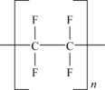
Formed by the polymerization of tetrafluoroethylene (TFE), the (–CF2–CF2–) groups repeat many thousands of times. The fundamental properties of fluoropolymers evolve from the atomic structure of fluorine and carbon and their covalent bonding in specific chemical structures. The backbone is formed of carbon–carbon bonds and the pendant groups are carbon–fluorine bonds. Both are extremely strong bonds. The basic properties of PTFE stem from these two very strong chemical bonds. The size of the fluorine atom allows the formation of a uniform and continuous covering around the carbon–carbon bonds and protects them from chemical attack, thus imparting chemical resistance and stability to the molecule. PTFE is rated for use up to (260°C). PTFE does not dissolve in any known solvent. The fluorine sheath is also responsible for the low surface energy (18dynes/cm) and low coefficient of friction (0.05–0.8, static) of PTFE. Another attribute of the uniform fluorine sheath is the electrical inertness (or nonpolarity) of the PTFE molecule. Electrical fields impart only slight polarization in this molecule, so volume and surface resistivity are high.
The PTFE molecule is simple and is quite ordered and so it can align itself with other molecules or other portions of the same molecule. Disordered regions are called amorphous regions. This is important because polymers with high crystallinity require more energy to melt. In other words they have higher melting points. When this happens it forms what is called a crystalline region. Crystalline polymers have a substantial fraction of their mass in the form of parallel, closely packed molecules. High-molecular-weight PTFE resins have high crystallinity and therefore high-melting points, typically as high as 320–342°C (608–648°F). The crystallinity of as-polymerized PTFE is typically 92–98%. Further, the viscosity in the molten state (called melt creep viscosity) is so high that high-molecular-weight PTFE particles do not flow even at temperatures above its melting point. They sinter much like powdered metals; they stick to each other at the contact points and combine into larger particles.
PTFE is called a homopolymer, a polymer made from a single monomer. Recently many PTFE manufacturers have added minute amounts of other monomers to their PTFE polymerizations to produce alternate grades of PTFE designed for specific applications. Generally, polymers made from two monomers are called copolymers, but fluoropolymer manufacturers call these grades modified homopolymer when the copolymer is used at less than 1% by weight. DuPont grades of this type are called Teflon® NXT Resins. These modified granular PTFE materials retain the exceptional chemical, thermal, anti-stick, and low-friction properties of conventional PTFE resin, but offer some improvements:
• Weldability
• Improved permeation resistance
• Less creep
• Smoother, less porous surfaces
• Better high-voltage insulation
The copolymers described in the next sections contain significantly more of the non-TFE monomers.
11.1.2. Polyethylene Chlorotrifluoroethylene
Polyethylene chlorotrifluoroethylene (E-CTFE) is a copolymer of ethylene and chlorotrifluoroethylene. Figure 11.2 shows the molecular structure of E-CTFE.
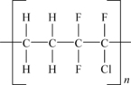
This simplified structure shows the ratio of the monomers being 1–1 and strictly alternating, which is the desirable proportion. Commonly known by the trade name, Halar®, E-CTFE is an expensive, melt processable, semi-crystalline, whitish semi-opaque thermoplastic with good chemical resistance, and barrier properties. It also has good tensile and creep properties and good high frequency electrical characteristics. Applications include chemically resistant linings, valve and pump components, barrier films, and release/vacuum bagging films.
11.1.3. Polyethylene Tetrafluoroethylene
Polyethylene tetrafluoroethylene (ETFE) is a copolymer of ethylene and TFE. The basic molecular structure of ETFE is shown in Figure 11.3.
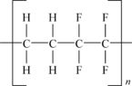
This depicted structure shows alternating units of TFE and ethylene. While this can be readily made, many grades of ETFE vary the ratio of the two monomers slightly to optimize properties for specific end uses.
ETFE is a fluoroplastic with excellent electrical and chemical properties. It also has excellent mechanical properties. ETFE is especially suited for uses requiring high mechanical strength, chemical, thermal, and/or electrical properties. The mechanical properties of ETFE are superior to those of PTFE and FEP. ETFE has:
• Excellent resistance to extremes of temperature, ETFE has a working temperature range of −200–150°C.
• Excellent chemical resistance.
• Mechanical strength ETFE is good with excellent tensile strength and elongation and has superior physical properties compared to most fluoropolymers.
• With low smoke and flame characteristics, ETFE is rated 94V-0 by the Underwriters Laboratories Inc. It is odorless and nontoxic.
• Outstanding resistance to weather and aging.
• Excellent dielectric properties.
• Nonstick characteristics.
11.1.4. Fluorinated Ethylene Propylene
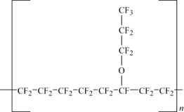
If one of the fluorine atoms on TFE is replaced with a trifluoromethyl group (–CF3) then the new monomer is called hexafluoropropylene (HFP). Polymerization of monomers (HFP) and TFE yield a different fluoropolymer, fluorinated ethylene propylene, called FEP. The number of HFP groups is typically 13% by weight or less and its structure is shown in Figure 11.4.
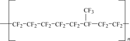
The effect of using HFP is to put a “bump” along the polymer chain. This bump disrupts the crystallization of the FEP, which has atypical as-polymerized crystallinity of 70% versus 92–98% for PTFE. It also lowers its melting point. The reduction of the melting point depends on the amount of trifluoromethyl groups added and secondarily on the molecular weight. Most FEP resins melt around 274°C (525°F), although lower melting points are possible. Even high-molecular-weight FEP will melt and flow. The high chemical resistance, low surface energy, and good electrical insulation properties of PTFE are retained.
11.1.5. Perfluoro Alkoxy
Making a more dramatic change in the side-group than that done in making FEP, chemists put a perfluoro alkoxy (PFA) group on the polymer chain. This group is signified as –O–Rf, where Rf can be any number of totally fluorinated carbons. The most common comonomer is perfluoropropyl (–O–CF2–CF2–CF3). However, other common comonomers are shown in Table 11.1.
| Comonomer | Structure |
|---|---|
| Perfluoromethyl vinyl ether (MVE) | CF2CF–O–CF3 |
| Perfluoroethyl vinyl ether (EVE) | CF2CF–O–CF2–CF3 |
| Perfluoropropyl vinyl ether (PVE) | CF2CF–O–CF2–CF2–CF3 |
The polymers based on propyl vinyl ether (PVE) are called PFA and the perfluoroalkylvinylether group is typically added at 3.5% or less. When the comonomer is methyl vinyl ether (MVE) the polymer is called MFA. A structure of PFA is shown in Figure 11.5.
The large side group reduces the crystallinity drastically. The melting point is generally between 305°C and 310°C (581–590°F) depending on the molecular weight. The melt viscosity is also dramatically dependent on the molecular weight. Since PFA is still perfluorinated as with FEP the high chemical resistance, low surface energy, and good electrical insulation properties are retained.
11.1.6. Polychlorotrifluoroethylene
CTFE is a homopolymer of chlorotrifluoroethylene, characterized by the following structure shown in Figure 11.6.

The addition of the one chlorine atom contributes to lowering the melt viscosity to permit extrusion and injection molding. It also contributes to the transparency, the exceptional flow, and the rigidity characteristics of the polymer. Fluorine is responsible for its chemical inertness and zero moisture absorption. Therefore, PCTFE has unique properties. Its resistance to cold flow, dimensional stability, rigidity, low gas permeability, and low moisture absorption is superior to any other fluoropolymer. It can be used at low temperatures.
11.1.7. Polyvinylidene Fluoride
The polymers made from 1,1-di-fluoro-ethene (or vinylidene fluoride) are known as PVDF—polyvinylidene fluoride. They are resistant to oils and fats, water and steam, and gas and odors, making them of particular value for the food industry. PVDF is known for its exceptional chemical stability and excellent resistance to UV radiation. It is used chiefly in the production and coating of equipment used in aggressive environments, and where high levels of mechanical and thermal resistance are required. It has also been used in architectural applications as a coating on metal siding where it provides exceptional resistance to environmental exposure. The chemical structure of PVDF is shown in Figure 11.7.
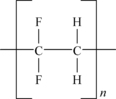
One of the trade names of PVDF is KYNAR®. The alternating CH2 and CF2 groups along the polymer chain provide a unique polarity that influences its solubility and electric properties. At elevated temperatures PVDF can be dissolved in polar solvents such as organic esters and amines. This selective solubility offers a way to prepare corrosion resistant coatings for chemical process equipment and long-life architectural finishes on building panels.
Key attributes of PVDF include:
• Mechanical strength and toughness
• High abrasion resistance
• High thermal stability
• High dielectric strength
• High purity
• Readily melt processable
• Resistant to most chemicals and solvents
• Resistant to UV and nuclear radiation
• Resistant to weathering
• Resistant to fungi
• Low permeability to most gases and liquids
• Low flame and smoke characteristics
11.1.8 THV™
THV™ is a polymer of TFE, HFP, and vinylidene fluoride. It is made by 3M Dyneon. It has the following properties:
• Low processing temperature
• Bonds to elastomers and hydrocarbon plastics
• Good flexibility
• Permeation resistance
• Excellent clarity and light transmission
11.1.9. HTE (Hexafluoropropylene–Tetrafluoroethylene–Ethylene copolymer)
HTE is a polymer of HFP, TFE, and ethylene. It is made by 3M Dyneon. It has the following properties:
• Broad processing range
• Very good chemical resistance
• Permeation resistance
• High light transmission in visible and UV
• Excellent dimensional stability and toughness
• Good electrical properties
11.1.10. Fluoroplastic Melting Points
11.2. Polytetrafluoroethylene
11.2.1. Fatigue Data
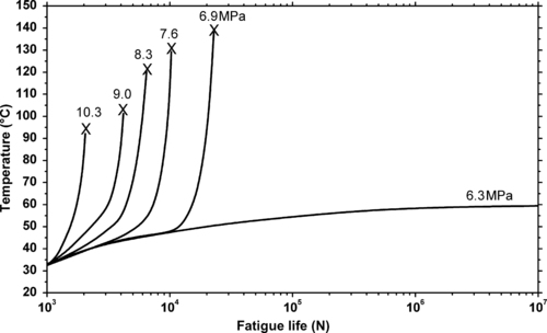
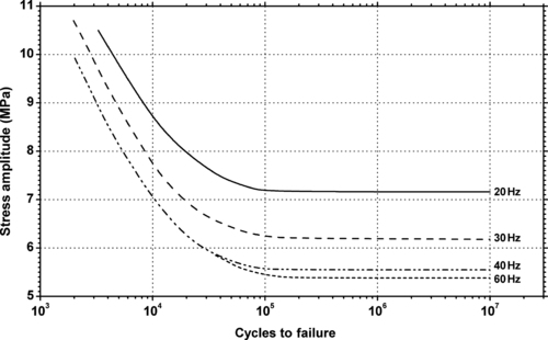 |
| Figure 11.8. |
| Flexural stress amplitude vs. cycles to failure at 23°C and different cycle frequencies of generic PTFE. |
11.2.2. Tribology Data
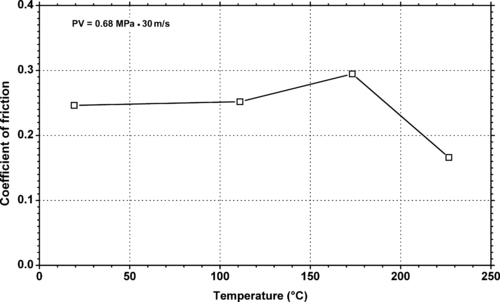 |
| Figure 11.11. |
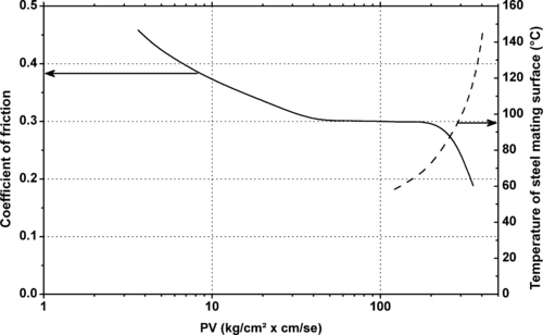
| Dynamic coefficient of friction vs. temperature of generic PTFE filled with 25% carbon. |
 |
| Figure 11.13. |
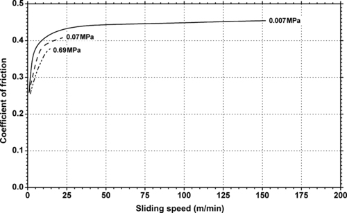
| Dynamic coefficient of friction vs. sliding speed and different pressures of DuPont Teflon® PTFE. |
11.3. Polyethylene Chlorotrifluoroethylene
11.4. Polyethylene Tetrafluoroethylene
11.4.1. Fatigue Data
11.4.2. Tribology Data
 |
| Figure 11.16. |
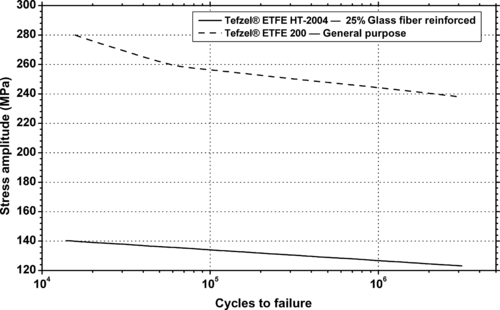
| The frictional behavior of DuPont Tefzel® HT-2004—25% glass fiber reinforced ETFE (thrust bearing tester, unlubricated). |
| Pressure (MPa) | Static Coefficient of Friction |
|---|---|
| 0.069 | 0.51 |
| 0.345 | 0.38 |
| 0.69 | 0.31 |
| 3.45 | 0.34 |
| Mating Surface | Pressure (MPa) | Velocity (cm/s) | Tefzel® | Metal |
|---|---|---|---|---|
| Steela | 6.9 | 2.5 | 16 | 4 |
| Steela | 6.9 | 2.5 | 16 | 4 |
| Steela | 6.9 | 2.5 | 16 | 4 |
| Steela | 6.9 | 2.5 | 16 | 4 |
| Steela | 6.9 | 10.2 | FAIL | – |
| Aluminumb | 2.07 | 5.1 | 1,220 | 1,220 |
| Aluminumb | 0.69 | 25.4 | 480 | 390 |
| Thrust bearing tester, no lubricant, ambient air temperature, metal finish 16 microinches (406nm). | ||||
| aSteel mating surface AISI 1018. | ||||
| bAluminum mating surface LM24M (English). | ||||
11.5. Fluorinated Ethylene Propylene
11.5.1. Tribology Data
 |
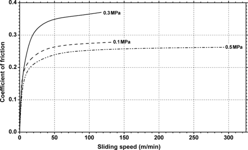
| Figure 11.17. |
| Dynamic coefficient of friction vs. sliding speed and different pressures of DuPont Teflon® FEP. |
11.6. Perfluoro Alkoxy
11.6.1. Fatigue Data
11.6.2. Tribology Data
 |
| Figure 11.19. |
| Dynamic coefficient of friction vs. temperature of DuPont Engineering Polymers Vespel® CR-6100—30% carbon fiber reinforced PFA. |
 |
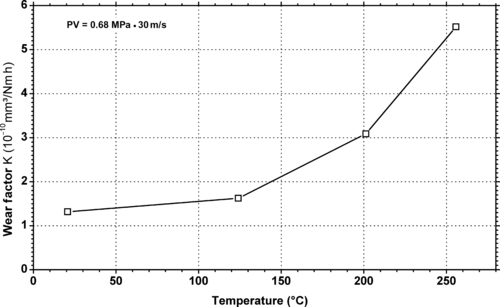
| Figure 11.20. |
| Wear factor vs. temperature of DuPont Engineering Polymers Vespel® CR-6100—30% carbon fiber reinforced PFA. |
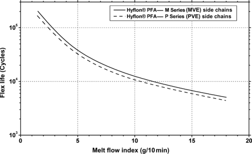
| Test Method | SI Units | M620 | M640 | M720 | P220 | P420 | P450 | |
|---|---|---|---|---|---|---|---|---|
| Flex Life (0.3mm film) | ASTM D2176 | ×103 cycles | 70–100 | 4–6 | – | – | 90–120 | 4–6 |
11.7. Polyvinylidene Fluoride
11.7.1. Fatigue Data
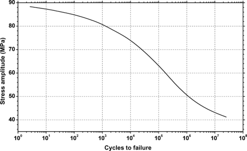 |
| Figure 11.21. |
| Tensile stress amplitude vs. cycles to failure at 25°C of Solvay Solexis Solef® PVDF (notched specimens, 0.4mm on each side). |
11.7.2. Tribology Data
..................Content has been hidden....................
You can't read the all page of ebook, please click here login for view all page.