
CHAPTER 2
Networking Fundamentals
In this chapter, you will learn:
• Network protocols and the OSI communication model
• TCP/IP design and functionality
• Network addressing
• Name resolution
Before we go anywhere, we need to talk about networking fundamentals. Too much of what comes ahead relies on a solid understanding of networking protocols. It can help to think about networking conceptually by breaking the functionality into chunks. When you have a clear understanding of a protocol’s role and where it fits in the collection of protocols, sometimes called a network stack, you will have an easier time putting everything together. There are a lot of moving pieces in any given network communication. You’ll need to understand how it’s all put together.

EXAM TIP You will need to know details about what the packets look like at the byte level and how they operate in the context of the architectural models that define their use and functionality.
In order to get there, we’re going to start with how the Transmission Control Protocol/Internet Protocol (TCP/IP) suite was developed. The TCP/IP architecture is presented as a layered stack, but how it came about is dramatically different from the other layered stack used to describe network communications—the Open Systems Interconnection (OSI) model. Once you have a grasp of the TCP/IP and OSI models, we can start filling in the layers with actual protocols—the ones you will need to have an understanding of not only for the exam but to better understand what we’ll be talking about in the coming chapters. As an example, understanding how firewalls function is significantly easier when you know how TCP/IP works. So, we start with the different models and then move to the fundamental protocols in the TCP/IP network stack.
History of TCP/IP
The history of TCP/IP can’t be discussed without briefly discussing the history of the Internet since their development has really been tied together inextricably. We have to set the Wayback Machine to the mid-1960s when the Advanced Research Projects Agency (ARPA) was developing plans for a computer network. While the money for it came out of the budget of the Defense Department, the goal of those involved in its origination was to be able to easily connect researchers across the country. In 1968, the plan for the creation of this computer network, later called the ARPANET, was approved by ARPA, and Bolt, Baranek, and Newman (BBN) was chosen as the company responsible for building this fledgling network. In fact, computer scientists at BBN originally proposed the idea of a network allowing for communication between computer users in different locations in the early 1960s, which inspired those at ARPA to build it.
In late 1969, the first link was up. Figure 2-1 shows a diagram of the connection between the very first Interface Message Processor (IMP) and the host it was intended to connect to on the network. An IMP was a ruggedized Honeywell minicomputer with custom-built components that was designed to act as a gateway to the network. Today, we typically call these devices “routers,” and they pass messages from one network to another.
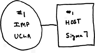
Figure 2-1 The first two nodes in the ARPANET
Initially, the interface software was called the Network Control Program (NCP). This interface software performed the functions that are now handled by the various protocols in the TCP/IP stack. In 1973–74, a specification for the Transmission Control Protocol (TCP) was written by Vint Cerf and Bob Kahn and proposed as a new protocol for host-to-host communications across networks. It wasn’t until version 3 in 1977 that the Internet Protocol (IP) was added to the protocol specification, splitting the routing off into a separate protocol and leaving packetizing, error control, and reassembly to TCP. Work on version 4, the version most computers around the world currently use today, was begun in 1977 and published as a Request For Comments (RFC) document in 1980.
January 1, 1983 was known as Flag Day. It was the day that TCP/IP officially supplanted NCP as the only approved protocol on the ARPANET. While this was when TCP/IP took over on the ARPANET, there were still several other global research networks in use and it took several more years for all those networks to be merged and TCP/IP to be migrated onto all of them. While IPv4 continues to be in widespread use to this day, IPv6, the next-generation protocol, was proposed in 1995. One of the motivations for the move to IPv6 has long been the coming exhaustion of the IPv4 address space. A number of mechanisms have allowed for the IPv4 addresses available to last far longer than originally expected. At the time of this writing, in early 2013, there is still no clear plan to migrate to IPv6 and we are not yet officially out of available IPv4 addresses, though certainly we are very near to the end without opening up address spaces previously marked as experimental.
Figure 2-2 provides some insight into the speed at which the Internet has grown. It took decades to get to a significant number of users, which happened in the 1990s. Since then, it’s really been an exponential growth curve, especially as less technologically advanced countries get online. On top of the exponential growth, the technology has been moving very quickly as more applications and protocols have been added to what the Internet is being used for. It took many years for TCP/IP to become the standard protocol on the ARPANET, and yet when you look at the number of technologies that have come into being in just the last few years, you can see the power of having ubiquitous Internet access.

Figure 2-2 The timeline of the ARPANET/Internet
Networking Stacks
Before talking about the different protocols, you’ll get some reference points by going through different models. Models are common in the communications world. As an example, when it comes to mobile communications, they talk about the IP Multimedia Subsystem, or IMS. Once you understand that model, you can talk about where the device you are selling or buying, for example, fits into the IMS architecture. This discussion of the models provides a clear set of demarcation points between the different protocols—each serves a specific function. There are architectural models we use to provide a shorthand language in order to easily discuss specific functionality without getting hung up in vendor specifics or additional technical descriptions. As it turns out, when it comes to TCP/IP, we have two models we can use to discuss functionality.
The first model is the seven-layer OSI model that is the product of the International Organization for Standardization (ISO). It is an abstract model that was originally developed as part of a need for a model for a distributed database solution. The second model was developed by creating a set of networking protocols for the creation of the ARPANET and is less of a model because it’s not abstract. The RFC that defines it refers to it as an architecture, so that’s what we will be calling it going forward. The TCP/IP architecture was effectively developed over 20 years before it was documented in RFC 1122.
EXAM TIP It’s important to know the order of the different layers in the two models. There may be questions that ask you to put them in the correct order based on receiving or sending packets.
The OSI Model
The Open Systems Interconnection (OSI) model was developed, interestingly enough, to assist in the creation of a large-scale database system. Initially, it sprang out of work at Honeywell Information Systems because they needed an architecture to support a distributed database system with access from multiple places. The seven-layer design came as a result of studying work at ARPA on the creation of protocols, as well as on network architecture at IBM called SNA (System Network Architecture). In the late 1970s, ISO requested the American National Standards Institute (ANSI) to develop some proposals for an architecture to support communications for data processing. The work from Honeywell was the only proposal that was presented to ISO, and as a result, it was the one that was approved.
The OSI model is a generic, protocol-agnostic architectural model that any set of protocols can be slotted into. It’s meant to describe a set of functionality in a clear and modular way, and as such is more about describing the ways in which protocols communicate and function together than it is about specifying or describing any particular protocol.
The Seven Layers
There are seven layers in the OSI model and each layer gets a set of tasks. Figure 2-3 shows the seven layers of the OSI model and the order they are typically presented in. Some people like to use mnemonics to be able to remember the order. One of my favorites comes from a student I had several years ago who suggested the mnemonic Please Do Not Touch Steve’s Pet Alligator. This presents the different layers from bottom to top, so we’ll go in that order.

Figure 2-3 The OSI model
1. Physical Layer At the bottom, the Physical layer is everything about the physical connection, from wires and jacks to electricity and light. The physical layer also takes into consideration different types of networking infrastructure like the connectors used, whether it’s an RJ45 connector and jack or an ST or SC connector for fiber. These physical manifestations may suggest some particular things about the next layer, but there are the physical attributes as well, which is all this layer is concerned with. The physical layer provides a place to talk about the hardware. When we are discussing network interfaces, cabling, switches, or anything else hardware-related, we are talking about the physical layer.
There are physical layer protocols that may be familiar to you. There are aspects of Ethernet, for example, that exist at the physical layer. The distinction between different network speeds like 100BASE-T and 1000BASE-T is at the physical layer. There are elements of IEEE 802.11, the Wi-Fi networking protocol, that are at the physical layer as well.
2. Data Link Layer Above the Physical layer is the Data Link layer, which describes how all of the data that has been flowing down from the top of the stack gets translated onto the physical transmission medium. This layer also handles things like error detection and correction should things like collisions occur on the physical medium. The Data Link layer also contains a set of addresses to ensure that systems can communicate with each other. While many protocols fall into the Data Link layer, the one most commonly used by people is the Ethernet. The Ethernet employs a Media Access Control (MAC) address. Any communication in layer 2 happens using a layer 2 address like the MAC address.
If you are talking about communication on the local network, you are talking about layer 2. Sometimes the collection of systems that communicates using layer 2 is called a broadcast domain or a collision domain. If you send a message to the broadcast MAC address and a system receives it, that system is in the same broadcast or collision domain as your system. Protocols you may be familiar with at layer 2 are Ethernet, 802.11, Frame Relay, Cisco Discovery Protocol (CDP), and Virtual Local Area Network (VLAN). Traffic that exists on the same local area network can be switched, meaning decisions about what port to send the traffic to happen using the MAC address, and switches know what MAC addresses can be found through which switch port.
3. Network Layer The third layer is the Network layer, which manages the network communication. Primarily this has to do with addressing traffic and ensuring it gets to where it is intended to go. As a result, routing takes place at this layer. Layer 3 gets traffic from one network to another, which is in contrast to layer 2, which is about getting traffic from one system to another on the same network. The addressing done at layer 3 is logical addressing. This is distinct from the physical addressing that happens at the Data Link layer. The Internet Protocol (IP) is probably the most common layer 3 protocol that you’ll recognize. The IP address provides logical addressing and the ability to aggregate addresses that MAC addresses don’t offer. This aggregation enables routing that happens at layer 3.
If a system is not on the same broadcast domain or LAN as your system, it will exist in a separate IP network address block. In order to get traffic between systems on separate IP networks (different LANs), that traffic has to pass through a layer 3 gateway, which means that it is routed. Devices that forward messages from one interface to a separate interface based on the IP address are acting as routers, even if they are not what you might think of as a traditional router.
4. Transport Layer Above the Network layer is the Transport layer. Depending on the protocol in use, the Transport layer may provide connection services as well as reliable delivery and the guaranteed ordering of messages. Additionally, the Transport layer offers multiplexing. This is done through the use of ports, which are the means of addressing at layer 4. Each system has 65,536 ports for both User Datagram Protocol (UDP) and TCP. This allows your system to be able to have multiple communication sessions open at any given time because, rather than just connecting to a logical address, like an IP address, an application can connect to an address and port combination, allowing multiple applications to communicate simultaneously.
The Transport layer is also responsible for end-to-end communication. This has several implications. The first is that the ports systems communicate to and from are in the Transport layer. Additionally, the Transport layer is responsible for any reliability that may be required. If messages need to be tracked to ensure delivery, that’s the job of the Transport layer. In most cases, the order that messages arrive in matters. If you were sending a Word document or an e-mail to someone, you wouldn’t want all the words to be out of order. It would mean that what you had written would become completely unintelligible.
5. Session Layer Above the Transport layer is the Session layer. The Session layer, not surprisingly, handles sessions. A session is like a conversation. It’s not just about sending a couple of messages back and forth, but instead a steady and coherent stream designed to accomplish a particular task. The Session layer offers authentication and authorization as well. It makes sure you are who you say you are but also ensures that you have the right permissions to access a particular resource. One of the protocols that falls into this layer is NetBIOS, which provides service-sharing services on Windows systems. NetBIOS establishes identity and permissions and also makes sure the session stays open until it is no longer needed. In the case of copying a file, for instance, the session needs to remain up until the file has been transferred. If something happens at the lower layer like a wire falling out if the clip on the RJ45 cable has come loose, NetBIOS will ensure the session gets reestablished, assuming the connection is reestablished within a short period of time.
6. Presentation Layer The Presentation layer is responsible for the representation of data. As a result, the XML and JPEG formats are at this layer. This is where the data gets converted from a structured representation to strictly a series of bits and bytes. Encrypting and decrypting data are examples of functions that would take place at the Presentation layer. There is a certain amount of translation services performed at this layer because it frees the application up from having to be concerned with how data gets represented at the lower layers of the stack. Again, this demonstrates a lot of modularity in the architectural model because this layer can have multiple implementations in any particular application, allowing these modules to be swapped in and out depending on the needs of the application. This modularity provides flexibility to the application.
7. Application Layer The Application layer is where the functions closest to the user exist. The Application layer is responsible for generating and handling the data that goes to or comes from the lower layers. There are, of course, a large number of protocols that would fall into this layer of the model. Simple Mail Transfer Protocol (SMTP), Internet Message Access Protocol (IMAP), and Post Office Protocol (POP) are all Application layer protocols responsible for allowing users to send and receive e-mail. The protocols specify how to direct the application on what to do with particular chunks of data. When you send e-mail, for example, the protocol implementation specifies a set of directives telling the server where to send the message, who it is being sent to, and when the message itself is being sent, as opposed to the directives being what is sent. These are all behaviors that relate to the application and not about how the message gets there.
Layer-to-Layer Communication
The OSI model is layered and modular. This means that protocols are stacked up and functionality within the different protocols is consistent with the layer they live at. This also means that, for the most part, you don’t have protocols that have functions that exist in three separate layers. You may have a protocol like Ethernet that appears to straddle two different layers, but in reality, something like Ethernet is actually composed of multiple protocols that work together to accomplish a larger goal. When we talk about “modular,” it means that any protocol can be swapped out and replaced with another one. As an example, you may replace TCP with UDP at the Transport layer.
There is one important concept that may seem obvious based on these layers but should be called out specifically anyway. Every layer adds a bit of information that it tacks onto the existing data, much like adding Lego blocks. Every layer adds another Lego block to the ones that are there until we get to the very last layer. When the packet gets to the other end, the blocks are removed in order and examined before having the next block removed. Another way to look at it is a factory that makes packets.
Imagine a factory where we are assembling packets that need to be shipped out as quickly as possible. Initially, a box gets delivered to the factory floor. That box needs to be wrapped up before it can be shipped. The factory is organized into different groups and each group is responsible for wrapping the box up in a different paper that has a different label on it. If you look at Figure 2-4, you can see the box that gets delivered is the Application Data. After the box of Application Data has been delivered, the Presentation group wraps the box in orange paper with a label on it. After that, the Session group wraps it in blue with a different label on it. Each group wraps it up in their color wrapper with a label attached, indicating what to do with it.
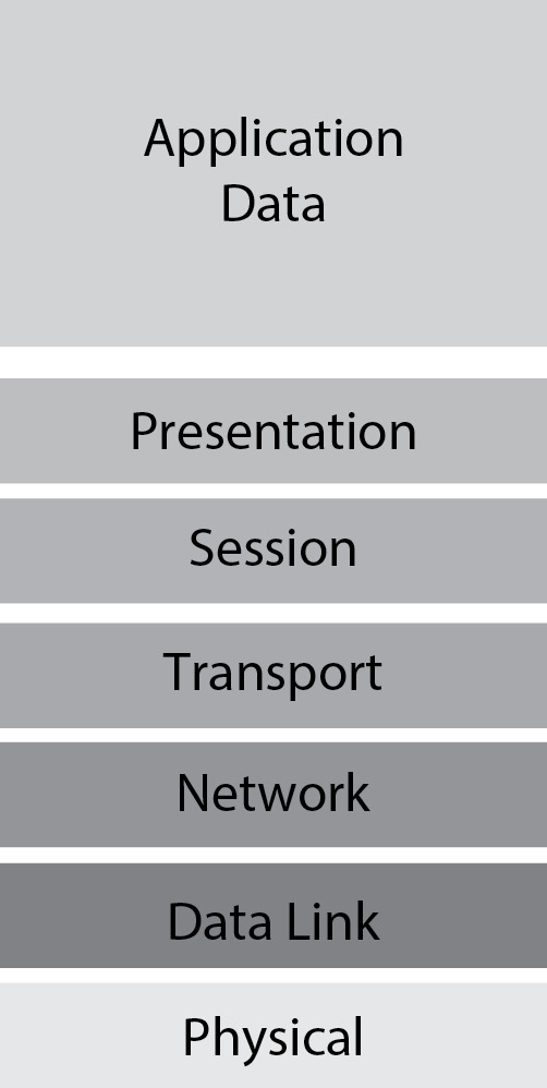
Figure 2-4 Layer-to-layer communication
The thing about this factory, though, is that it’s unionized, so when the box gets sent off and delivered, only members from the group that put each layer of packaging on are allowed to remove it. This is, in part, because only the members of each of the union groups know how to read the information that comes off. Any attempt by other union members to do the work is a violation and isn’t allowed.
As each package gets delivered, it may also make stops at delivery depots (routers) along the way. Each of these depots has members of the Data Link group to remove that packaging layer and then put a new layer of packaging on before sending the package off to the next depot on its way to the final destination. These depots are along the lines of the waypoints you will see if you track a package being delivered by FedEx or UPS.
This layered approach to packaging is how packets are handled in the network. The layer of packaging has to be removed by the right “group” within the operating system so they can decipher the label on that layer of packaging and determine where the packet needs to go next. After the Network “group” is done removing the IP information, it needs to determine whether it’s going to go off to the TCP, UDP, or some other group for packaging removal and handling. If the right component of the operating system doesn’t handle the appropriate layer, the packet handling and delivery will fail, which is why we have the modular, layered approach so each section can be handled correctly and efficiently. Without this approach, you would end up with one large group (program function) handling all data, which would mean a lot of inefficient data handling. This, in turn, may lead to delays in delivery of the data.
TCP/IP Architecture
The TCP/IP architecture, also called the DoD (Department of Defense) model, is defined in an RFC dated from 1989, well after TCP/IP had been in widespread use. It specifies the layers required for communication between Internet hosts. RFC 1122, as it was named, specifies four required layers. Any host on the Internet must implement all four layers, which means having at least one protocol in each layer. There is a difference between the TCP/IP architecture and the OSI model, which is one reason I’m referring to it as the TCP/IP architecture rather than the TCP/IP model. The way the TCP/IP suite of protocols is put together is not conceptual. The description of the protocols and how they work are essentially as-built rather than concepts, meaning the implementation was done either before the documentation or at the same time. Because the documentation of the fundamental protocols describes what was implemented rather than what should be implemented when it is built, the description of the entire suite is really an architecture rather than a model. This is very different from the OSI model, which takes a conceptual idea of network communications and abstracts out different functions, allowing protocols to be mapped to the different layers well after the fact.

NOTE RFC 1122 specifies that no matter which layer it is, protocols should follow one general rule called the Robustness Principle, which states “Be liberal in what you accept and conservative in what you send.” The idea behind this principle is to ensure interoperability. With a large number of vendors expected to implement the protocols, there will certainly be different interpretations of how the software that uses these protocols should operate. If you gracefully accept different communications than what you might send yourself, you will remain functional and also continue to communicate with the sender. This reliability and robustness are very important and are big reasons why TCP/IP became the de facto networking protocol implementation around the world.
Four Layers
Instead of the seven layers of the OSI model, the TCP/IP architecture is only four layers. When you look at it, though, and compare the functionality sets between TCP/IP and OSI, you’ll find that the bottom layer of the TCP/IP architecture includes the functionality of the bottom two layers of the OSI model. Similarly, the top layer in TCP/IP really comprises all of the functionality of the top three layers of the OSI model. Figure 2-5 depicts the four layers and the order they are presented in, from the bottom up.

Figure 2-5 The TCP/IP model
Link Layer The Link layer corresponds to the bottom two layers in the OSI model. The Physical layer and the Data Link layer are both represented in the functionality of the Link layer from the TCP/IP model.
Each layer has a protocol data unit (PDU) as a way of talking about the data in each layer separately from the other layers. Once a chunk of data makes it through the Link layer, it is called a frame. The Link layer is responsible for formatting a frame and getting it out onto the wire. There are a handful of requirements for the Link layer according to RFC 1122. The big ones are related to supporting IP encapsulated in Ethernet and related protocols. The Link layer also handles the Address Resolution Protocol (ARP), which translates higher layer addresses to a Link layer address. The Link layer is also responsible for preventing ARP floods and ensuring that the cache is kept up to date by flushing it as necessary. As noted in the RFC, which makes specific reference to it in order to ensure that TCP/IP will interoperate with another emerging standard, Ethernet falls clearly into the Link layer.
Internet Layer Not surprisingly, the Internet layer is where the Internet Protocol (IP) resides. RFC 1122 says that the Internet layer has two primary functions. The first one is choosing the next hop gateway, which means that it’s responsible for handling routing functions. The second one is reassembling fragmented IP datagrams. Additionally, the Internet layer might also deliberately fragment datagrams and it should provide error and diagnostic functionality. Internet Control Messaging Protocol (ICMP) is at this layer to provide the error and diagnostic functionality.
The Internet layer in the TCP/IP model corresponds to the Network layer in the OSI model. The functionality is the same, though the specification of the TCP/IP model is very clear about the specific protocols that fill the functions for this layer. The PDU in the Internet layer is called a packet. You may hear any discrete set of network transmission as a packet. Technically, this is incorrect if it includes the Link layer header. If we are only talking about Internet headers and above, we’re talking about a packet.
Transport Layer The Transport layer handles end-to-end communication for systems. While IP does bear some of the burden of that end-to-end communication, IP is really a best-effort delivery system and doesn’t pay attention to whether datagrams arrive or not. This is the responsibility of the Transport layer. The Transport layer makes sure, if it is necessary, that datagrams arrive intact and in order. Sometimes it’s not necessary to keep track of whether datagrams arrive or not, and we just want them sent. If they are received, great, if not, we aren’t going to spend any time worrying about retransmitting. This sounds similar to the functionality of the Internet layer, but we need the additional functionality so we add on additional protocols. RFC 1122 is very clear that UDP and TCP are the protocols for this layer. UDP simply provides a datagram service. There is no reliability and no connection establishment. The datagrams are transmitted with absolutely no guarantee of their delivery or sequence when they arrive. TCP, on the other hand, provides both of those things. When you use TCP, you are guaranteed, within reason that datagrams will arrive at the other end and will arrive in the correct order.
The PDU for this layer depends on the protocol being used. If we are using UDP, the PDU is called a datagram. The datagram is very simple and, as noted previously, carries no agreement about whether the datagram will get to its endpoint. The PDU for TCP is a segment. In either case, whether we’re talking about a datagram or a segment, we’re talking about the Transport layer headers and the data from the Application layer.
Application Layer In the TCP/IP model, there are two types of application protocols. The first is protocols that provide services to users directly. This would be a protocol like Telnet, for example. Telnet provides remote login services to users. The other type of application protocol would be a support protocol like the Simple Network Management Protocol (SNMP) or the Domain Name System (DNS) protocol. There are no requirements mentioned in RFC 1122 for the Application layer. In reality, the top three layers of the OSI model are accommodated in this top layer of the TCP/IP model. The Application layer here handles all of the functions of the Session, Presentation, and Application layers. This is primarily because this model is more focused on the network components and less on the aspects that deal more closely with the users. As a result, there aren’t really any requirements or guidelines mentioned in RFC 1122.
EXAM TIP You will be expected to know the core protocols at a very low level. You will also need to be able to determine specific pieces of data when only shown a packet dump in hexadecimal, which means knowing how many bits each piece of header data consumes.
Protocols
At this point, you may be wondering about all of these protocols we’ve been discussing. Before going into the individual protocols that make up the core TCP/IP suite, it may help to define what a protocol actually is. In computing, we use protocols a lot, but we don’t need to go to computing to find a functional definition of protocols. We make use of protocols every day, whether we realize it or not. When you greet a friend on the street and say hello to them, they likely respond with a similar greeting, whether it’s “Hi” or “Hello” or “How’s it going?” They probably make eye contact, however fleeting it may be. When you send e-mail to someone, you likely begin by saying something like “Dear Recipient” or “Hello” or some other greeting. These are examples of protocols and they are really just the rules we follow to assist in understanding the communication that is happening. They are markers of the way we communicate so you know when a conversation is beginning or ending. There may be specific protocols around the way you communicate with special people, whether it’s the Queen of England, the President of the United States, or the parent of someone you are taking out for the first time. We probably are a bit more deferential to those people than we may be to someone we see every day. This is a protocol that we use to confer a measure of respect on those people, or maybe it’s just a way of making them feel special.
When we are talking about computer-based protocols, it’s really very similar. A protocol is a set of rules that we define that helps make communication faster, more efficient, and easy to understand. If one computer was to send a HELLO command while the other was expecting a LOGIN command, for example, that would lead to some communication challenges and they would be stuck waiting for the right command or response. As a result, we put down a set of very clear definitions of these communications. These are defined, from an Internet-based protocol perspective, in Request For Comments (RFCs) that are managed by the Internet Engineering Task Force (IETF). Any time you want to know specifically how a protocol is expected to act, you should read the RFC for that particular protocol. You can easily locate RFCs by using the search features at the IETF RFC Editor website (www.rfc-editor.org).
Internet Protocol
The Internet Protocol handles a couple of really important functions. The first function is that of providing a logical address by which systems can be accessed. This logical address also allows us to group systems together, which a physical address doesn’t allow us to do. As a result, we have the ability to route messages quickly and easily between systems on disparate networks. There are also other functional components of the Internet Protocol that require different header fields. Currently, we primarily use version 4 of the protocol, though usage of version 6 is increasing, primarily due to limitations of version 4, which is now approaching 40 years old. There are two basic functions that IP is meant to implement: addressing and fragmentation. The headers implement fields to assist with those functions.
IP Version 4 Headers
The IP header is defined as 24 bytes of data, though commonly you’ll see 20 bytes since the other 4 bytes are options and padding. Table 2-1 has all of the fields in the IP header as well as their length and purpose.

Table 2-1 IP Headers
Listing 2-1 demonstrates how a packet is broken up.
Listing 2-1 Sample IP Header

The hexadecimal in the top line is the raw packet. The hexadecimal is grouped into two digits because it takes two digits to make a byte—each hexadecimal digit uses four bits. The first byte, 45, includes the IP version (4) and the header length in 32-bit words. There are five 32-bit words in the header, which translates to 20 bytes since there are four bytes in a 32-bit word. The next byte (00) is the DiffServ Code Point and the Explicit Congestion Notification, which converts to a 0 for both values. The total length of the datagram as seen in byte locations 3 and 4 is 03 3D, which is 829 bytes in decimal. The IP ID field has 1E EB for the hexadecimal values. The ID field is two bytes long. There is no particular need to convert the ID field to decimal, so we’ll leave it alone at 1EEB. Flags take up the next three bits, and bit 2 is set there. It’s worth taking a moment to demonstrate how to determine what bits are set from the hexadecimal.
In order to figure out the values from a set of bytes where there is a split, you need to change it over to binary and find where the bits are set. When we convert 40 00 to binary, we get 0100 0000 0000 0000. You can see that, of the first three bits, in these two sets of bytes there is only one bit set. In this case, that’s the Don’t Fragment bit, which is bit 2. This means we are not going to fragment the datagram. TTL is the next byte (40) and that converts to a 64, so the packet can go through 64 intermediate devices prior to the packet expiring and needing to be dropped.
The protocol field is one byte with a value of 06. Fortunately, this isn’t difficult to convert. Since the first digit is a 0, 6 in hexadecimal is still 6 in decimal. The checksum is two bytes, and while we could go through the process of converting it to binary, we will just leave it at 5DE8. Those two bytes were 11 and 12, which brings us to byte 13. The last eight bytes are the source and destination IP address. In this case, we need to convert the hexadecimal back to decimal so it makes more sense to us. C0 converts to decimal by multiplying 12 × 16 and getting 192. A8 converts to binary by multiplying 10 × 16 and adding 8, leaving us 168. Continuing the conversion in the same way leaves us with a source address of 192.168.1.22 and a destination address of 172.194.75.103.
EXAM TIP You will need to know how to convert hexadecimal to decimal. Although you are given a calculator, it’s a basic calculator. You will be presented with bytes in hexadecimal form so the leftmost digit (corrected to decimal as necessary) is multiplied by 16 and then you add the rightmost digit to get the final decimal value.
Exercise 2-1: Hexadecimal Conversion
a. Convert 0xCD from hexadecimal to decimal.
b. Convert 132 from decimal to hexadecimal.
In looking at the sample header in Listing 2-1, there are several fields that are geared toward ensuring the validity of the data as sent. There is a header length, which not only ensures that the data can be checked, but also tells the parser where to begin looking for the next section of data: beyond the header. There is a field for total length, which can be checked to ensure the entire packet is intact, and finally, there is the checksum, which should guarantee that the data that’s received is the same as what was sent and that it wasn’t corrupted along the way. This shouldn’t suggest it wasn’t altered along the way, because any alteration would come with a new checksum, which is easy to calculate and insert.
IP is also a best-effort delivery protocol. This doesn’t mean that it’s half-hearted in its attempts to get messages from one endpoint to another endpoint. What it says is that it does the very best job that it can do to get a message out to the recipient but that there are things that can happen in the network and at intermediate systems that it can’t control. Since IP has no capability to retransmit or even track messages through the network, the best it can do is say that it will get a message out onto the network and hope that the network does the right thing in getting the message to the recipient. This is why it’s called best-effort. If an application needs something better than that, either it can use an upper layer protocol like TCP to ensure messages get delivered in the right order or it can implement mechanisms in the Application layer protocols to accomplish the tasks that need to be accomplished.
Addressing
As I mentioned, one of the primary purposes of the Internet Protocol is to provide a logical address for systems to communicate with. IP version 4 has a 32-bit address separated into four octets. In Listing 2-1, the final eight bytes are the two IP addresses: the source and the destination. An IP address is composed of two sections: the network address and the host address. You can determine which part of the address is the network and which part is the host based on the subnet mask that goes hand in hand with the address itself. In order to determine which part is the network and which is the host, you perform a bitwise AND between the IP address and the subnet mask. The result of the AND will give you the network portion. The remainder will be the host portion.
EXAM TIP You need to be able to pull apart a subnet mask and convert the values into the number of bits. This will allow you to recognize how much of an IP address is the network and how much is the host.
Exercise 2-2: Subnetting
Given the subnet mask 255.255.255.128, how many bits are used for the network and how many bits are used for the host?
A subnet mask is created from the most significant bit to the least significant bit. Ordering our most significant bit on the left side, the first subnet mask you can have is 10000000 00000000 00000000 00000000. The bit in that first position gives you a value of 2^7 or 128. The reason it’s 2^7 and not 2^8 in spite of it being in the eighth position is that in order to get a value of 1, we have to start counting positions at 0 because 2^0 is 1. The resulting subnet mask is 128.0.0.0. The next possible value is 192, because in order for the mask to work, it has to be filled in from the left side or else there is the possibility of gaps, and then we don’t get a coherent result when we perform the AND with the IP address in order to get the network address. The first position is 128 and the next position has a value of 64, so adding the two together, we get 192. Table 2-2 shows the bit values and the resulting mask value.

Table 2-2 Subnet Values by Bit Pattern
The subnet mask will also tell you how many hosts can be on a particular network. A network with a subnet mask of 255.255.255.0 leaves eight bits for host values because the last octet is clear. Eight bits will give us 256 values (0–255), but two of those values are already spoken for. Every network has both a network address and a broadcast address, which takes two addresses away from the number of hosts we can have. The network address is always the lowest address in the network range; the broadcast address is always the highest. In the case presented here, .0 would be the network address and .255 would be the broadcast address.
Every bit of subnet mask added divides the number of total addresses by two. Taking a bit of subnet away doubles the number of total addresses. While this may seem a trivial thing to say since we are talking about powers of two, remembering it makes calculating values a lot easier by just doing the math from a known starting point. For example, a typical subnet mask of 255.255.255.0 has 24 bits of subnet mask and 256 possible values. If we add another bit of subnet mask, we end up with 255.255.255.128 and we halve the possible address values to 128. From there, we subtract off the network and broadcast, of course, and we have 254 possible addresses that can be used. If we take away a bit of subnet, we have 255.255.254.0 and 512 possible values in the host portion of the IP address.
Classful Addressing
Initially, IP addresses were allocated in classes. These classes are based on the value in the first octet of the IP address. There are five classes that were defined, which actually leaves a significant number of addresses unused. The classes are defined in Table 2-3.

Table 2-3 Classful Address Definitions
The bit pattern shown in Table 2-3 indicates the most significant bits in the first octet of the address. For example, a Class A address will always have a 0 in the most significant bit of the first octet, which means that the maximum value you can ever achieve in that octet is 127 since the 128 bit is never set. Similarly, with a Class B address, a 0 in the second most significant bit means that the 64 bit will never be set, so the most you can ever get is 191 because you need the 64 bit to be set to get to 192.
There are some special addresses that should be noted. The addresses 127.0.0.0–127.255.255.255 are allocated for loopback addressing. Any address in that range could be used to refer to the local system, although commonly, the address 127.0.0.1 is used for this purpose. The addresses 169.254.0.0–169.254.255.255 are reserved for self-configuration in cases where a server can’t be located to provide an IP configuration. This is a link-local address, which means that it can’t be used anywhere other than the local network the system is attached to. Addresses are determined randomly in order to assure that a number of systems can come up on the same network without any additional configuration.
Finally, there are three blocks of addresses that are called private addresses. They are defined in RFC 1918, which specifies that by convention they will not be routed across the Internet. They are often called non-routable, though that’s a little misleading. They can be routed—in fact, many organizations do use large blocks of these addresses and instead route them internally. Since they are private addresses and require no allocation from anyone, there will be significant overlap, which means that attempting to route them across something like the Internet would result in ambiguous behavior. These private address blocks are as follows:
10.0.0.0–10.255.255.255
172.16.0.0–172.31.255.255
192.168.0.0–192.168.255.255
With classful addressing, the subnet mask is assumed in certain situations. This means that in the case of a Class A address, without any further subnetting, you would have 2^24 addresses (16,777,216) available in the network, which is a pretty unwieldy network. As a result of this limitation, there needed to be a way of carving up addresses into more manageable blocks while still being able to easily transmit the size of the network in a meaningful way.
Another block of addresses that is considered special is the range of addresses from 127.0.0.0–127.255.255.255. You will typically see the address 127.0.0.1 in use. It’s called the loopback address or the localhost address. Any address within that range can serve that purpose. Similar to the private addresses, the loopback or localhost addresses are, by convention, not routable on the Internet. The last block of reserved addresses is the multicast addresses, which start at 224.0.0.0 and end at 239.255.255.255. Multicast addresses are used to send traffic to multiple recipients simultaneously.
EXAM TIP The private addresses and the loopback addresses are considered not routable on the Internet, though it’s sometimes expressed in a short-hand as simply being not routable.
Classless Inter-Domain Routing
The problem with classful addressing was that it was limiting. If you were provided a Class A address space, for example, you had 4 million addresses and no ability to share those out in any useful way. There had to be a better way, and as it turns out, there was. We needed to be able to subnet, which meant using subnet masks indicating which portion of an address identified the network and which part was for hosts. With this, we could chunk up large address spaces and share them out with friends and family, as seemed fitting. However, it’s unwieldy to send an entire subnet mask, so instead we send just the number of bits that belong to the network. This is done by appending a / onto the network address, followed by the number of bits: 192.168.1.0/24. Since we aren’t using classes to indicate the number of subnet bits, this notation where the number of subnet bits is indicated is called Classless Inter-Domain Routing (CIDR). The example /24 would indicate a subnet mask of 255.255.255.0. A 255 in each octet indicates there are 8 bits in use for the network in those octets. We have three octets of 8 bits, which is 24 bits.
Fragmentation
With a modular design like TCP/IP, you get a lot of flexibility, but you also get circumstances where you have to make accommodations for cases where two layers may not match exactly. The higher layer protocols like TCP and UDP allow for large messages, both allowing for 65,535 bytes to be transmitted. Lower layer protocols like Ethernet, however, have much smaller allowable sizes. The maximum transmission unit (MTU) of Ethernet is 1500 bytes, which includes the headers. As a result, you end up with situations where messages need to be fragmented into smaller-sized packets so they can be transmitted. IP is responsible for taking care of this, and there are headers that make that possible. The first IP header that allows fragmented datagrams to be put back together is the IP identification header. All packets belonging to a fragmented message will have the same IP identification number.
Internet Protocol Version 6
In the 1990s, the Internet Engineering Task Force, the group responsible for managing protocols across the Internet and generally trying to improve operations, recognized that IPv4 had a limited life to it. One of the reasons for that was because in the 1990s there was an explosion in usage of the Internet, which meant that addresses were being consumed at a rapid rate. The IETF determined that they needed a way to accommodate many more addresses, and so the next version of IP had to achieve that goal. Additionally, a number of other defects had been identified in the existing version and those needed to be fixed. IPv6 needed to have a larger address space, be more efficient in processing capabilities as the messages were passing through routing devices, and also have some level of security built in.
IP Security, also known as IPSec, was developed as a core part of IPv6. It was spun out and adapted for IPv4, but the way it operates is part of how IPv6 was created. You can use Authenticated Headers (AH) to ensure that messages haven’t been tampered with. You can also use Encapsulating Security Payload (ESP) to encrypt the message contents. These two mechanisms provide a range of security capabilities and can be configured to be used on a per-system basis, depending on the implementation of security policies on each system.
Addressing
As noted, there had to be a much larger address space available in IPv6. The existing address space was 2^32 addresses, or roughly 4 billion addresses. This may seem like a lot but good-sized chunks have been carved out for other purposes and the need to assign them in blocks means there will be some inefficiency and a number of addresses that go unused. With people having multiple devices that need addresses now, that 4 billion, even if it could be fully used, is inadequate. IPv6 has an address space that is 128 bits wide. This gives us 2^128 addresses, which is a number large enough that it simply makes more sense to write it as 2^128 rather than trying to write out all the digits. If it’s easier to think of it another way, it could also be expressed as 3.4 × 10^38. That’s a lot of addresses, and you can probably be confident that we won’t be running out of these addresses any time soon.
An IP address still has the primary function of needing to identify both the host and the network portion, in spite of the version change. We still haven’t changed the need to route packets from one system to another, and in order to route, we need network identifiers in the addresses. Because of that, we are using the CIDR notation to indicate the number of bits in the network portion.
An IP address is composed of eight 16-bit words. A word is just a group of bytes bound together. In the case of an IP address, it made some sense to bind two bytes together to create a 16-bit word. All addresses in IPv6 are written in hexadecimal because it’s more convenient. Two hexadecimal digits can represent one byte, so each word of an IP address is expressed in four hexadecimal digits. 8890:7764:f0ca:445d:9097:123a:cdb0:de41/64 is an example of an IP address. While it’s quite a mouthful, it is the easiest way to express an IPv6 address.
There are shortcuts, however. You may find a situation where there are long sections of 0s, for example. In that case, you can abbreviate the address by just leaving the sections blank. You might have an address that was written fe80::1234:78fa as an example. The :: section indicates that there are 0s that fill all of those places.
Headers
The IP header has been simplified, but because of the address size, the total header length is still larger. Table 2-4 describes all of the fields in the IPv6 header, as well as their length and purpose. Table 2-5 shows the layout of the IPv6 headers, organized in 32-bit word blocks.
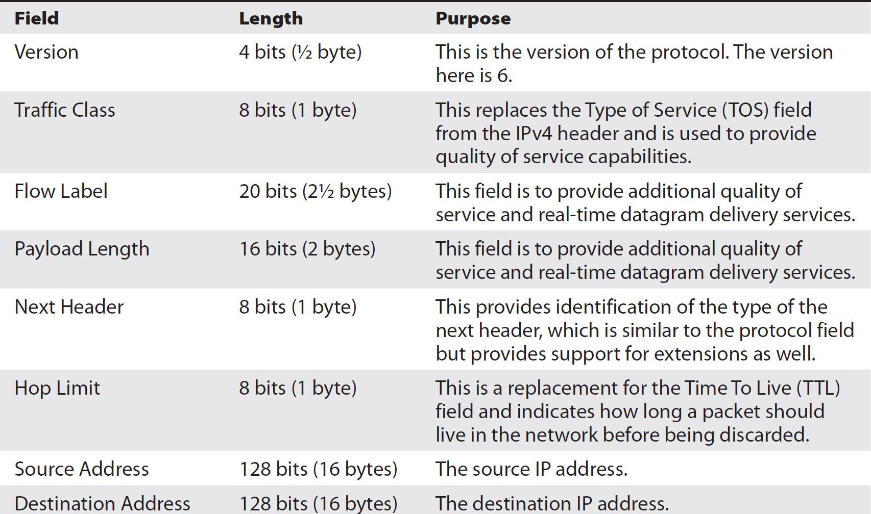
Table 2-4 IPv6 Headers

Table 2-5 Layout of IPv6 Headers
Internet Control Message Protocol (ICMP)
ICMP is a support protocol for the other protocols in the TCP/IP suite. It is designed to provide error and diagnostic messages to assist in the delivery of messages. When packets run into problems on the network, ICMP messages are sent back. As an example, if you are trying to send a message to a system that is offline, an intermediate device ahead of that system, like a router or firewall, may send back an ICMP message indicating that the system is unreachable. You may also get a response back when a port is unreachable. There are two utilities that get used regularly as part of network diagnostics that make use of ICMP. The first one is ping. ICMP has two messages that ping makes use of. The first is an echo request, and the second is an echo reply. You would send an ICMP echo request to a system to verify its reachability, and if it is up and functional, it would send back an ICMP echo reply.
The second utility that makes use of ICMP is the traceroute utility. There are different implementations of traceroute that operate slightly differently, but they all rely on ICMP in the same way. Traceroute operates by way of a system sending a message out with the destination of the target, but the TTL is set at 1 to begin with. When it reaches the first router on the path, the TTL is decremented and becomes 0, which means it needs to be discarded. When it’s discarded, the router sends back an ICMP error message indicating that the TTL expired. The TTL then gets set to 1 and keeps getting incremented, while the system that replies with the ICMP error message is noted, until finally the ICMP message changes to a destination unreachable message. Either the system itself is unreachable or the port is unreachable. Either way, traceroute knows that the trace is complete once it receives this error message.
NOTE In Windows, because of the historical restriction on the length of filenames, the utility is called tracert but the functionality is the same as traceroute, and it relies on ICMP error messages in the same way.
ICMP uses a header to convey the information. The header is composed of eight bytes. The first byte is the type indicating the type of message that is being conveyed. Each type may have several different codes to specify a different condition. For example, the port unreachable message and the host unreachable message are both different codes inside a Type 3 message, indicating that the destination is unreachable.
The type and code both take up one byte. Table 2-6 is a listing of all the relevant types and codes. There are two additional bytes used for a checksum. The checksum is used like the checksum in other protocols—to ensure that the message hasn’t been corrupted in transit. The ICMP header has four additional bytes that get used to convey additional information, depending on the specific message.

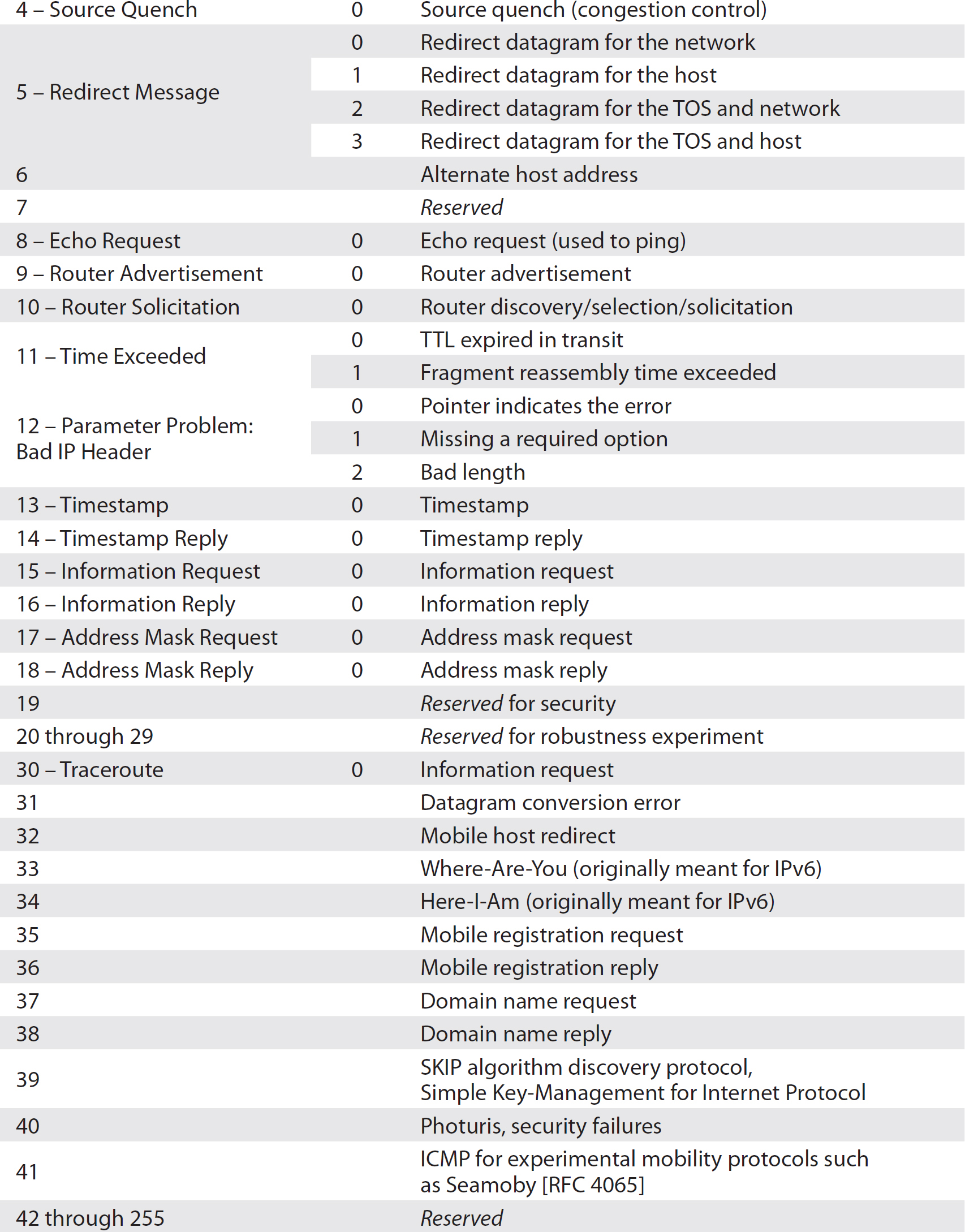
Table 2-6 ICMP Types and Codes
Transmission Control Protocol (TCP)
TCP is a Transport layer protocol providing, among other things, multiplexing. If we were to try to communicate with another system without having the ability to multiplex, we’d only have the ability to have one communication at a time, which would be pretty limiting. Additionally, it provides a reliable transport, ensuring that each datagram gets to its destination with all the data in the correct order.
The multiplexing in TCP is accomplished by using port numbers. Since TCP uses two bytes to designate a port number, we can have ports 0–65,535 giving us a total of 65,536 ports to use. This provides a lot of communication potential. Since we expect to receive messages back from those we communicate with, we need both a source port and destination port. When we send a message, it gets delivered to the destination port, but when that system then needs to communicate back to us, it turns the port order around and the original source port becomes the destination port on the return trip. As a result, the source port is effectively bound to the original sending application. The IP stack then knows that when the return communication comes back, it goes back to the application that started the process.
EXAM TIP Expect that the exam will have questions where you will need to be able to decipher portions of the TCP header from just a set of raw bytes expressed in hexadecimal. Knowing the order and size of each component of the header is going to be critical to doing well.
Table 2-7 describes all of the fields in the TCP header, as well as their length and purpose. Table 2-8 shows how the different fields are arranged by byte.

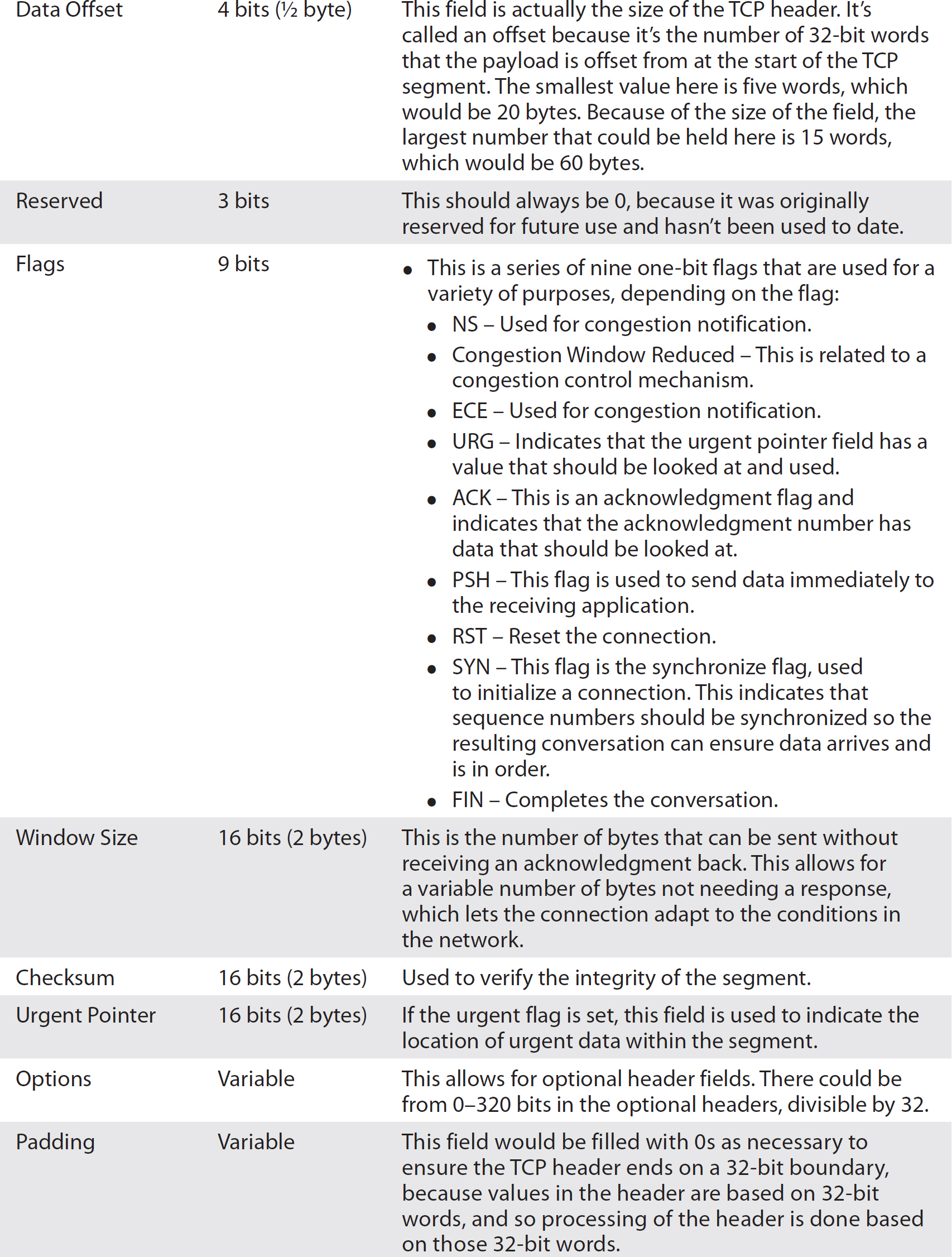
Table 2-7 TCP Headers
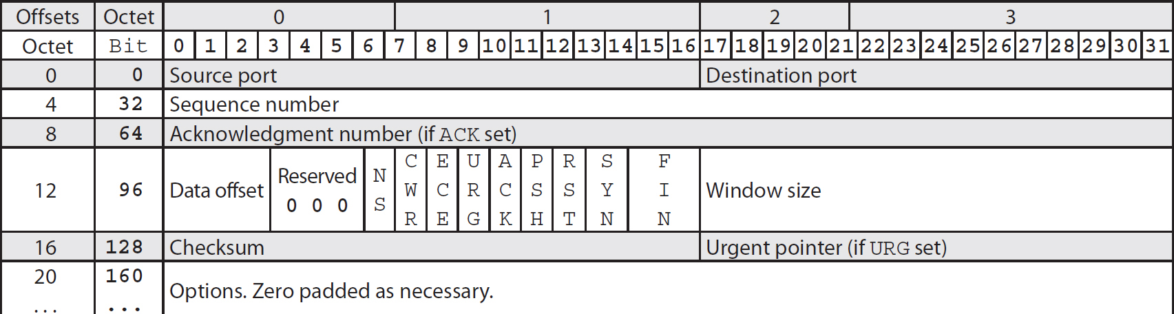
Table 2-8 TCP Header Layout
Reliable Delivery
TCP achieves reliable delivery through two mechanisms. The first is the three-way handshake that is used to establish a connection. The three-way handshake achieves a couple of objectives. The first is that each side assures that the other side is there, is listening, and is able to respond. The second, a side effect of the first, ensures that the communication is not being forged with a fake address, also called spoofed. Since the three-way handshake requires that the originator of the communication respond in a coherent way, it generally rules out the possibility of spoofing. Figure 2-6 shows a communication stream between a client and a server, presented as a ladder diagram so that it’s easier to follow along with the explanation.
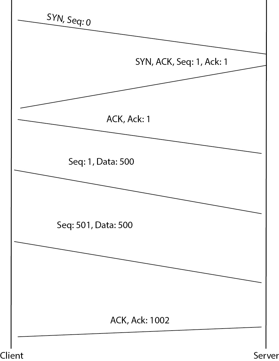
Figure 2-6 Ladder diagram showing communication
The three-way handshake is a pretty simple process, but it’s critical to the way TCP/IP works. The first step of the three-way handshake is to send a SYN (synchronize) message. This is a TCP segment with the SYN flag set. This message is the same as someone welcoming an acquaintance in the street with a Hi! It says “I am looking to begin a conversation with you.” Along with the SYN flag being set, the client initiating a connection to a server would send an initial sequence number. This sequence number establishes a baseline so that messages can be ordered correctly since we can’t guarantee the messages won’t get reordered by the network. This lets the receiving system put all the data back into the correct order. It also allows for a guaranteed delivery because the receiving system can send a verification back to the sending system that individual messages were received.
The second message is sent from the server back to the client. In this case, two flags are set. The first flag is an ACK, acknowledging that the initial SYN message was received. The second flag is a SYN flag so that the server can reply with its own initial sequence number. This does the same thing as the first sequence number. It establishes a baseline from the server to the client with a sequence number. The reason for doing this is because when you establish a connection with another system, the communication is going to be two-way for the most part. It’s not typically a send-only connection in one direction. If it were, you would probably use a different protocol from TCP. Since both sides are going to be sending data, the server end needs an initial sequence number as well.
The final message is the client sending back an ACK message indicating that it received the SYN message from the server. This finishes the baseline establishment between the two systems so they both have initial sequence numbers set and those numbers have been acknowledged. While the setup of a connection is three messages, the teardown of an established connection is actually four messages. When one of the systems wants to tear a connection down, it sends a message with the FIN flag set. This says that it is done communicating and wants to tear the connection down. The system receiving the FIN message will reply with an ACK to that message, but it can also keep its side of the communication stream open for a period of time, so it also needs to send a FIN message when it is done communicating. Again, since communications are two-way, both sides need to indicate that they are ready to terminate, and it doesn’t have to be mutual. When one side is done, it says so and then just waits until the other side is done. Figure 2-7 shows a Wireshark capture of a communication stream from one system to another with the first three messages being the three-way handshake. You can see the flags that are set in the capture image.
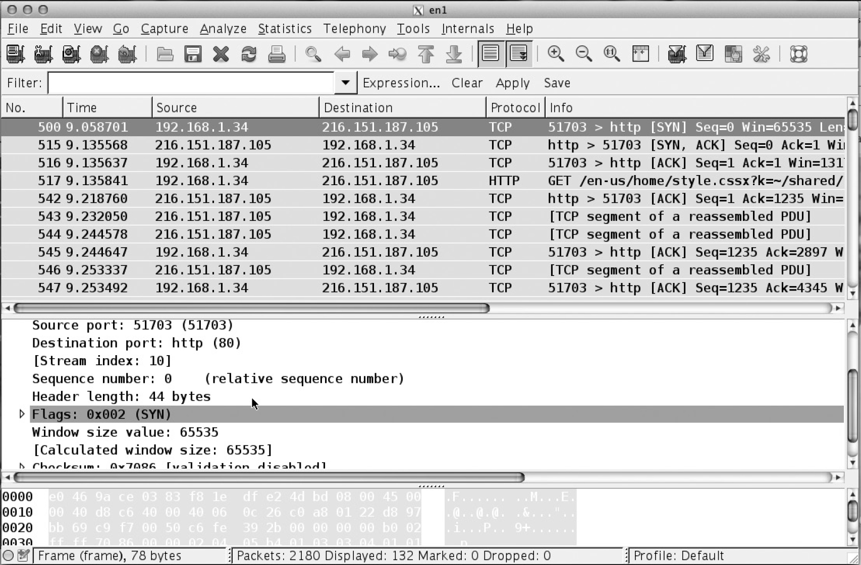
Figure 2-7 Wireshark capture of a three-way handshake
Another component that prevents spoofing and ensures reliability is the pairing of the sequence number and the acknowledgment number. This can take a little bit of looking to sort out exactly what’s going on, but it’s an important part of how TCP operates. The initial sequence number should be generated randomly. A random sequence number will prevent sequence number prediction, which could make a system vulnerable to session hijacking. The best way to understand how the sequence number and acknowledgment numbers work together is to see it in practice. So, as an example, let’s say that client C is sending a message to server S, and for the sake of simplicity we will use small numbers for the sequence and acknowledgments. In practice, these numbers would be large and random but smaller numbers make it easier to do calculations so we can see what happens. The first message would be as follows:
C -> S Flags: SYN, Seq: 100
This is the first stage of the three-way handshake and the initial sequence number is set. Nothing else is set in this message.
S -> C Flags: SYN, ACK, Seq: 200, Ack: 101
This is the SYN/ACK message. In order to distinguish one side of the communication stream from another, I set the sequence number to 200. This is the initial sequence number from the server to the client. The acknowledgment indicates that the first message was received and indicates the next byte expected from the client. This is done by simply incrementing the sequence number that was sent by one because it was a SYN message.
C -> S Flags: ACK, Ack: 201
This is the ACK message completing the three-way handshake. The ACK flag is sent indicating that the acknowledgment flag carries some data that should be looked at, and in this case the acknowledgment number is just an increment of the initial sequence number indicating that the SYN message was received.
C -> S Flags: none, Seq: 1, Data: 500 bytes
C -> S Flags: none, Seq: 501, Data: 500 bytes
S -> C Flags: ACK, Ack: 1002
The first two messages in the code block indicate that there is data, and the sequence number is the initial byte number. The first message indicates that this is the first byte of data. The second indicates that 500 bytes have previously been sent in other messages. The response from the server to the client indicates that it received bytes 1–1001. The acknowledgment number is the number of the byte expected next from the sender. Since 1000 bytes were sent and the first byte was byte number 1, we have sent bytes 1–1001, so the next byte in the stream should be 1002.
TCP also includes a sliding window mechanism. This sliding window ensures that a receiver isn’t flooded with messages. It also helps ensure messages get delivered. The window size is advertised in the messages and can be changed at any point. If a window size were 200 bytes, for example, the sender would only be able to transmit 200 bytes before going any further if those 200 bytes haven’t been acknowledged by the receiver. The window locks the transmission into place. If the 200 bytes were broken up into segments A, B, C, and D, all 50 bytes long, the window would be locked at segment D. If A, C, and D are all received by the recipient, the window can’t slide to the next set of bytes until B has been received. This ensures that no message has been lost and it makes it easier to reassemble.
In actuality, the sender in that case wouldn’t even know that C and D had been received since it can’t acknowledge those messages until the missing bytes are delivered. While it’s possible to do selective acknowledgment, it’s not common. Typically, bytes are acknowledged in order, meaning that you can acknowledge a number of segments simultaneously by simply acknowledging the last one received, which indicates that all the intermediate segments were also received.
In the preceding example, where we have segments A–D, if A and B are sent and received, the window can then slide along to C, D, E, and F, and that becomes the window until the first segments within the window are sent and acknowledged. As the window slides, we get orderly and controlled delivery.
A sender and a recipient may perform what is called a slow start if there is uncertainty about the other side’s ability to send and receive. This is where the window size is set small and increased slowly as the messages pass back and forth and each side gets an idea of how quickly messages can be sent and acknowledged.
Keep in mind, though, that the window size being advertised is the number of bytes you are willing to receive at a time. You have no control over the number of bytes you will send because your send window is your recipient’s receive window and they have control over their receive window. A sender must comply with the window size advertised by their recipient.
The Mitnick–Shimomura Attack
In the 1980s and 1990s, Kevin Mitnick was spending a lot of time breaking into systems. At some point in the 1990s, he broke into the system of a graduate student named Tsuturo Shimomura using a TCP sequence number prediction attack. Shimomura was able to follow this attack and capture messages to demonstrate how it worked. In the following, you will see the output from a packet capture. In the messages x-terminal.shell > Apollo.it.luc.edu.1000, notice the SYN/ACK message portion of a three-way handshake. These messages are all in bold face. When you compare the sequence numbers, which have been italicized, you will see that the sequence numbers go up by a predictable amount. Because the sequence numbers were predictable, Mitnick was able to spoof the connection between Shimomura’s system and a server.
While the important part of this is the sequence number prediction, there is more to the attack than just sequence number prediction. Mitnick had to take the system he was pretending to be out of the equation so it wouldn’t be able to reply. Once he had the three-way handshake completed from sequence number prediction, he was able to send shell commands to the system under attack, which would allow him to later on make a legitimate connection because he had opened up trust relationships
The Mitnick–Shimomura attack and the way it works is important because some of the implementations of TCP didn’t adequately protect the systems by using random data. It wasn’t until this attack became public that vendors realized that predictable data could be used to attack a system. This particular attack also highlights some of the vulnerabilities inherent in the design of TCP/IP, which led to some of the changes that went into the next version of IP.
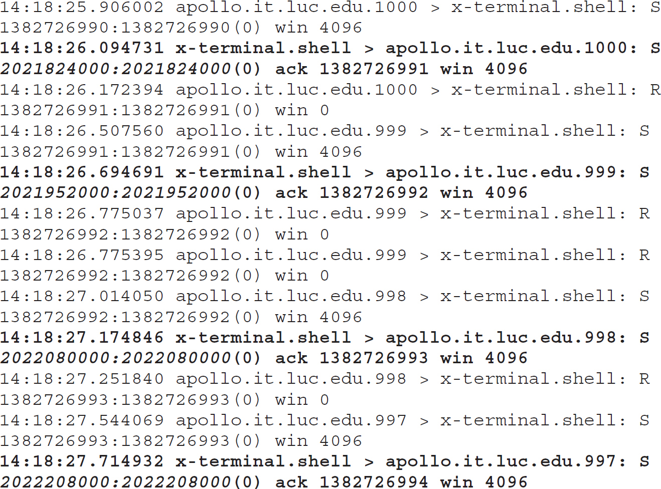
In this packet capture, we see that Mitnick, on the Apollo.it.luc.edu system, sent SYN messages to the target, x-terminal on the shell port, which would be port 23. He did this several times, sending an RST message after getting the SYN/ACK back so he could understand the pattern being used for the initial sequence number. Once he had gathered enough data from this set of messages, he was able to predict the sequence number. This was necessary to be able to send spoofed messages over TCP, because he needed to be able to respond with appropriate ACK messages, letting the target know that the messages had been received. This allowed him to carry on a conversation, knowing the data he was sending and the messages he expected to receive, along with the length of those responses.
EXAM TIP The exam may have a question with a capture sample that looks like this. You should be looking at the sequence numbers to compare them. If you see a pattern (subtract one sequence number from the previous sequence number), the system is vulnerable to TCP sequence number prediction, which is the attack that Kevin Mitnick used.
He needed to be able to predict those, because when you are acknowledging received messages, the sequence number increments by the number of bytes that have been received. In order to know what that value is over time, you need to know what the initial sequence number is. This should be a random value, but older implementations of TCP/IP didn’t implement random values, as they didn’t anticipate the possibility of predicting the sequence number for a spoofing attack.
User Datagram Protocol (UDP)
UDP is considered an unreliable protocol. This does not mean that it fails a lot. What it means is that there are no mechanisms built into the protocol that would ensure that messages get delivered and that they are delivered in the correct order. Lacking those mechanisms, UDP provides no guarantees that messages won’t get dropped or arrive out of order, so applications that require message fidelity should not rely on UDP.
Actually, there are several applications where UDP is more than useful—it’s necessary. A typical application would be streaming media like voice or video. Voice over IP (VoIP) would use UDP to carry voice traffic. The reason for this is simply because when you are using something in real time, like a voice communication, your senses are capable of filling in the gaps where small amounts of data may be lost. Additionally, you don’t want to spend the time waiting for messages to come in out of order and then have to reorder them. Since our senses can fill in spaces that aren’t really there by automatically filling in what makes sense, we can drop messages that are out of order or not delivered and still be able to make some sense of what’s going on. What we are really looking for is speed. We want messages to hit the wire as quickly as possible and get to the recipient fast. We also don’t want to spend a lot of time processing the message, so the headers in UDP are minimal and easy to process quickly.
Similar to TCP, UDP offers multiplexing via port numbers. We have source and destination ports, which get reversed on the return communication. Unlike TCP, though, there is no way to ensure that messages get delivered. This is one reason why doing a port scan against UDP ports can be timely since we can’t always guarantee what no response to a UDP message means. If a message doesn’t get a reply, we can’t assume it’s because there is no application listening. It could have been dropped in the network or potentially discarded by a firewall in front of the target system.
EXAM TIP Know the order of the headers for UDP. You may be expected to decode a set of raw bytes provided in hexadecimal in order to determine the source port or destination port, for example.
Table 2-9 describes all of the header fields contained in UDP as well as their length and purpose.
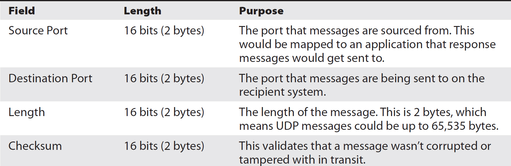
Table 2-9 UDP Headers
Table 2-10 displays the structure of the UDP header in a way that shows it in chunks of 32-bit words that other headers are organized in.

Table 2-10 UDP Header Structure
Domain Name System (DNS)
People typically have a hard time juggling a lot of numbers, and since that’s the core of the addressing scheme for systems on the Internet, there needed to be a better way. Initially, it was done with a file that got shared around to all of the hosts on the Internet. This was acceptable because there were so few systems in the early days and everyone knew who was on. You could create a file that had a mapping of hostnames and IP addresses. Not surprisingly, this wasn’t very flexible or scalable. If you needed to make a change because you had added or decommissioned a system, you needed to get that change to the person who updated the hosts file and it needed to be sent out to everyone. Fortunately, in an age where there were really large systems like mainframes and mini-computers, the number of changes was generally low. New sites were coming online on a regular basis, though. As a result, the Domain Name System (DNS) was created to have a way of looking up information about hostnames and IP addresses. It would give flexibility and scalability to the growing network.
DNS is a hierarchical system, and to best understand it you have to read it right to left. A system name that includes the domain name as well is called a fully qualified domain name (FQDN). On the right side of an FQDN, you have the top-level domain (TLD). Figure 2-8 is a visual representation of the hierarchical nature of DNS, and it may help to follow along using the figure. You may be most familiar with seeing .com or maybe .org here. Those are examples of top-level domains, and those TLDs have a map of the second-level domain. In the case of my own domain name, the second-level domain would be WasHere. My full domain name, including the TLD, is washere.com. If I were to have a system in my DNS tables, the FQDN would be something like opus.washere.com and that would map to an IP address, so rather than having to connect to the IP address, you would simply connect to the hostname.

Figure 2-8 Visual representation of the DNS hierarchy
In addition to the domain name, you may have subdomains. As an example, if my organization had a research and development lab, I may call the subdomain for that part of the organization labs.washere.com. The web server for that subdomain would be www.labs.washere.com.
Most often, you’ll see these hostnames offering up service names rather than something more colorful. This makes it easier to remember. As a result, you get www.microsoft.com or mail.google.com or something along those lines. The reason for that is because, again, it makes it easier to remember. These service-based hostnames may actually be mapped to a different hostname altogether. They are used for convenience so everyone knows how to get to the web server for a particular domain.
DNS queries are recursive because the names are hierarchical. A series of root servers hold all of the authoritative name servers for each second-level domain. An authoritative name server is where the definitive responses for any given domain are. The administrators for each domain would be responsible for maintaining the tables of all the hostnames for that domain. The root servers would point to the DNS server maintained by each organization. Recursive means that the first response points to another server that would need to be queried. Again, by way of example, if you were looking for www.washere.com, you would go to the root server to get the authoritative name server for the domain washere.com. The root servers would reply with an IP address. Your system would then send the query off to the authoritative name server asking for the IP address for www.washere.com. If there were subdomains involved, there would be additional queries involved to get the authoritative name server for the subdomains.
You can see a Wireshark capture of a DNS query in Figure 2-9. Notice that the transport protocol is UDP and the request is for an Internet address for A (Address) record of www.mheducation.com. The query is followed later by a response. Much of the recursive nature of the DNS queries happens with the actual DNS server, not on the client side where this capture was taken.
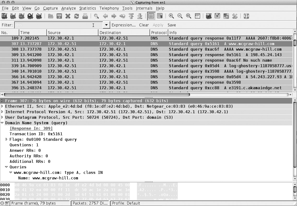
Figure 2-9 Sample DNS query
Chapter Review
It can be challenging to keep straight all of the header fields for the core protocols of the TCP/IP suite—IP, TCP, and UDP—but it’s one of the certification objectives. Plan to spend a fair bit of time here. It will be worthwhile exploring tcpdump or Wireshark and seeing how the protocols look in real life. Wireshark provides a graphical look, as well as extensive protocol decodes, so it may be more helpful to those who are new to packet captures and protocol interactions. Seeing the field values from an actual network communication stream can help put things into context. Understanding IP addressing requires getting your head around the math at the bit level and knowing powers of two. Once you have a handle on the value of all the bit positions, you are in a good place to understand subnetting and IP addresses. IPv6 offers some significant changes, primarily in the way that hosts are addressed. Having 16 bytes for addressing gives a lot of room for hosts, and making use of the number of network bits, as with CIDR notation, gets rid of the subnet mask and makes it easier to understand what’s happening between the network and host component of the address.
Questions
1. With the following IP header, what is the destination IP address: 45 00 03 3D 1E EB 40 00 40 06 5D E8 C0 A8 01 16 AD C2 4B 67
A. 192.168.1.38
B. 173.195.74.108
C. 173.194.75.103
D. 103.75.194.137
2. What can you say about the following packet capture?

A. This is a sequence number prediction attack.
B. This is a normal remote login sequence.
C. This is a SYN flood.
D. These are unexpected messages.
3. If you see the IP address fe80::0050:8790:4554:2300/16, the :: indicates what?
A. There are 1s between the ::.
B. There are 0s between the ::.
C. This indicates empty space.
D. This is a delimiter between addresses.
4. In the network 192.168.5.0/23, what would be the broadcast address?
A. 192.168.255.255
B. 192.168.4.0
C. 192.168.1.0
D. 192.168.5.255
5. In the address ab00:fc87:234a:0090:5120:ffab:bc8a:0098/23, what does the /23 indicate?
A. The number of bits in the network portion of the address
B. The address of the router
C. The host address
D. The position in the address where the messages should be sent
6. How many bits are in the NETWORK portion of the following address block:

A. 24
B. 32
C. 27
D. 29
7. What class is the address 170.19.82.45?
A. A
B. B
C. C
D. D
8. What is the order of messages in a three-way handshake?
A. SYN, ACK, ACK
B. ACK, SYN, ACK
C. SYN/ACK, ACK, SYN
D. SYN, SYN/ACK, ACK
9. Which of the following is a private address (RFC 1918)?
A. 128.15.29.0
B. 10.45.60.10
C. 192.192.192.1
D. 1.1.1.1
10. Which utility makes use of ICMP to function?
A. icmpstat
B. netstat
C. whasup
D. traceroute
11. Which TCP header field determines how much data can be transmitted before receiving an acknowledgment?
A. IPID
B. Sequence Number
C. Window Size
D. PSH Flag
12. Which protocol has only an eight-byte header?
A. IP
B. UDP
C. TCP
D. ARP
13. What is a significant change between IPv4 and IPv6?
A. No UDP is needed IPv6.
B. TCP doesn’t use a three-way handshake in IPv6.
C. Layer 2 is bypassed in IPv6.
D. The address is longer in IPv6.
14. Which of the following is a new field in IPv6?
A. Flow Label
B. IPID
C. IP Address
D. Don’t Fragment
15. Which of the following is not one of the layers in the OSI model?
A. Application
B. Transport
C. Internet
D. Presentation
Answers
1. C. The last four bytes of the header are the destination address. Converting the hexadecimal back to decimal gets the correct IP address. You would do this by converting each byte to decimal. You can do this by multiplying the value in the 16s place (what you would normally think of as the 10s place) by 16, and then adding the value in the 1s place. So, AD would be 10 × 16 + 13 = 173. If you start in the fourth octet and get the result, you may only need to calculate one value.
2. A. This is a sequence number prediction attack. If you look at the sequence number from the server, you’ll see that it increments by a predictable amount each time. You would subtract 2021824000 from 2021952000 and see that it is 128000. Similarly, subtracting 2021952000 from 2022080000 will also give you 128000. That is a predictable value.
3. B. When you see :: in an IPv6 address, this indicates there are 0s that aren’t being displayed.
4. D. 192.168.5.0/23 indicates that there are nine bits available for host addresses. The additional bit carries over into the third octet. In this case, you’d get two consecutive numbers in the third octet that were part of the same network. In this case, 0–1, 2–3, 4–5 are all in the same network. Since 5 is the top of the range and the broadcast is the last address in any network range, the correct broadcast address for this network is 192.168.5.255. The network address would be 192.168.4.0.
5. A. Just as with CIDR, in IPv6, the /23 would indicate the number of bits in the network portion of the address.
6. C. The first three octets are full, which means 24 bits are used for the network. Twenty-five bits would put a 128 in the last octet, 26 would be 192, and 27 would be 224, because we add on the next less power of two each time we add a bit. Thus, we have 128 + 64 + 32.
7. B. The first octet of the address is 170. A Class A address has 0–127 in the first octet, Class B is 128–191, and Class C is 192–223. 170 falls into the Class B range.
8. D. The three-way handshake in TCP begins with a SYN message to synchronize the initial sequence number. The response to that message acknowledges the SYN with an ACK and sends a SYN of its own, so the second message is a SYN/ACK. The final message is the sender responding with an ACK to the SYN.
9. B. The address 10.45.60.10 falls into the range 10.0.0.0–10.255.255.255, which is the Class A private address space.
10. D. The traceroute utility makes use of ICMP for a time exceeded in transit message and a destination unreachable message.
11. C. The window size is the amount of data that can be sent before getting an acknowledgment from the other end. This makes sure that the two sides are in sync and one side doesn’t get too far ahead before an issue is identified. The IPID field is an IP header field used to identify all frames that belong to a single packet. The sequence number is used to keep messages in order. The PSH flag is used to push data to the application without buffering further.
12. B. The UDP header is just eight bytes. The IP header is 20 bytes long. The same is true as the basic headers for TCP, though TCP headers can be longer if there are options set. ARP is not a protocol that has headers. ARP makes use of layer 2 headers.
13. D. An IPv6 address is 128 bits while an IPv4 is only 32 bits. UDP has not been removed from IPv6. The layer 2 address can be part of the IPv6 address, but the layer 2 address is still necessary. TCP continues to use the three-way handshake in IPv6.
14. A. While the IPv4 headers have some quality of service capabilities, those capabilities are enhanced significantly in IPv6. Flow Label is one of the fields that helps to implement quality of service. All of the other fields exist in IPv4.
15. C. There are some similarities between the OSI model and the TCP/IP architecture. The Application layer and Transport layer are the same between them. The Presentation layer is a part of the OSI model. While the Network layer is part of the OSI model, the Internet layer is part of the TCP/IP architecture. The Internetwork layer doesn’t exist.
Exercise Answers
Exercise 2-1
a. You convert the hexadecimal CD to decimal by multiplying C, or 12 in decimal, times 16. 12 × 16 = 192. Add D, or 13 in decimal, to the result and you have 192 + 13 = 205.
b. In order to convert 132 to hexadecimal, you may pass through binary first. This means you have to think in powers of 2. In a byte, 2^7 is 128 and the most significant bit in that byte. That means we know we have a 1 in the most significant bit position. 132 – 128 is 4. 2^2 is 4, so the third position from the right is a 1. If we break the byte up into nibbles, it looks like this: 1000 0100. This makes it easy to convert to hexadecimal, since a hexadecimal digit is represented as four bits in binary. What we end up with is 84. The most significant digit in that number is the leftmost position, which is 16^1 × 8, which is 128. The least significant digit is just the value in that position (16^0 × 4).
Exercise 2-2 Twenty-five bits are used for the network, with three sets of eight bits, plus an additional bit in the last octet. There are a total of 32 bits available, so that leaves 7 bits for the host.