
Chapter 4. Modeling Details
CD Files
Kila_Feet.mb
Kila_Hair.mb
Kila_Ear_01.mb
Kila_Ear_02.mb
Kila_InnerMouth.mb Kila_Head.mb
Kila_Complete.mb
KilaFront.jpg
KilaSide.jpg
KilaFaceFront.jpg
KilaFaceSide.jpg
We are really moving along with Kila—the end is in sight. In this chapter we will give our character’s head some important details: hair, eyes, ears, and the inner mouth. Then we will work on her clothing, adding her crop-top T-shirt, and complementing the jeans with a sash and belt.
Creating Hair
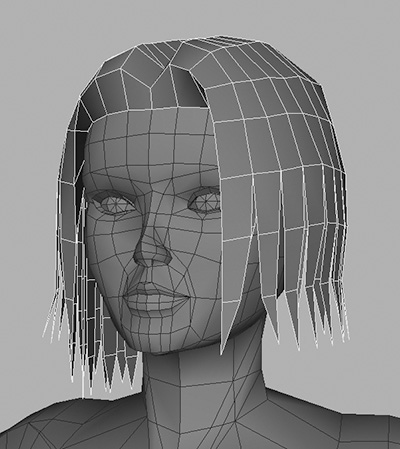
You are probably looking at your character and thinking, “She doesn’t look much like what she’s supposed to....” Her lack of hair is the main reason for Kila’s unexciting appearance right now; you will be surprised at how much interest a hairdo adds to a character’s overall look.
Let’s start work on giving Kila some hair, by first loading the file you last worked on, Kila_Feet.mb. Look at the original concept artwork, or the image planes, and you’ll see that her hair is not fully symmetrical, so we will, to an extent, need to model the whole coiffure. Her hair is parted down the center, so what we can do is model one-half of the hairdo, then duplicate and mirror it, and edit the copy to have the slightly different look of the other half.
To begin, let’s remove some of the polygons from around the back of the head, the ones that will not be seen. Using Figure 4.1 as a guide, mark in the hairline using the Split Polygon tool, and then delete the unwanted polygons.

Note
You will only need to work on one side of the model as the other is merely a mirrored instance.
We are finished editing the main model now. Carving in the hairline gives us a starting point for creating the hair. We’ll begin with the inner layer—the hair lying closest to her face and head.
Inner Layer
We want the hair to look layered, giving it some depth. To create this effect, we will use strips of polygons starting at the hairline and building our way out.
1. Create a new polygonal plane like the one seen in Figure 4.2, by going to Create > Polygon Primitives > Plane and opening up the options window. Set the configuration to Width 0.02, Height 0.15, Subdivisions Along Width 1, and Subdivisions Along Height 5.

2. Move the new plane, matching it up to the polygons on the side of the head as shown in Figure 4.3. Duplicate the plane and position the new copy next to the original while trying to stay between the two vertices on the head, so the width of the strip matches the width of the polygon underneath it.
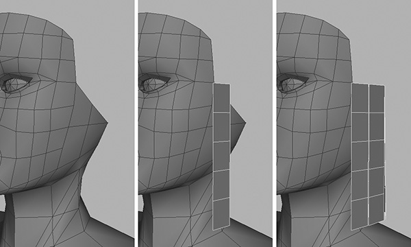
3. Continue duplicating and positioning strips until you have five of them placed around the head. Remember, we are only working on half of the head for now, so don’t place the strips all the way around.
We now have our innermost strips for the hair; next we will create the outer layer that starts at the top of her head and drapes over the inner layer of hair. With these two areas in place, we can create other strips to place in between, amplifying the layered effect we are after.
Outer Layer
Start work on the outermost layer of hair.
1. Duplicate one of the current strips, position it at the top of the head, and rotate it by 90 degrees (Figure 4.4). Make sure the top of the strip lies at the same position as the center of the model; this point will act as the part in her hair.
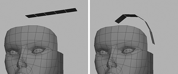
2. Edit this strip, bending it to follow the shape of her head. You will notice in Figure 4.4 that the strip is too short. It does need to be longer, so select the edge nearest the bottom and use the Extrude Edge tool to add three more divisions.
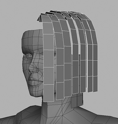
3. As demonstrated in Figure 4.5, duplicate the new strip several times, until you have filled out the top, side, and back of the left side of her head.

4. Looking from the side, the hair seems very flat. Manipulate each strip individually, altering the position and scale to make the hair higher at the crown than in the front (Figure 4.6).
Time to do a bit of tidying up. In the perspective view, look down onto your hair geometry; it should look like mine in the left panel of Figure 4.7—a bit of a mess. Before moving on, combine the upper parts of the strips and weld some of the vertices around the top, trying for the result shown on the right in Figure 4.7. Don’t work all the way down the strips; just concentrate on the top five rows of vertices for now.

We now have the base geometry in place for the top of her hair. Create a mirrored instance to use as reference, and you’ll see something like Figure 4.8 (left). Take some time now to work on the shape a little more. It may help to snap the vertices together between the strips, but do not weld them yet. Aim for something like Figure 4.8 (right).

The Front Hairline
Let’s now create the front hairline, filling in the gap between her forehead and hair. Remove the mirrored instance of the hair for now so we can concentrate on just one side.
1. First, hide the top layer of hair by selecting it and pressing Ctrl+H/Cmd+H. Leave the underneath visible because you will need it for this part of the modeling.
2. Duplicate one of the side strips and position it above her forehead, following the example in the middle panel of Figure 4.9.

3. Adjust the vertices until you have the arrangement shown in the right panel of Figure 4.9, snapping the lower vertices to the ones on the top of her forehead.
4. Bring back the geometry that makes up the top of her hair by pressing Ctrl+Shift+H/Cmd+Shift+H. Now snap the upper vertices of this newly added forehead strip to the front section of her hair (Figure 4.10).

FIGURE 4.10 Snap the upper vertices of the forehead strip to the front part of the outer hair layer.
5. Now combine both pieces of geometry—the hairline strip and the front parts of her hair—and weld the vertices at the front, making a single, solid object.
6. To complete the front hairline area, you need to hide the rest of the model, making just the hair visible. This time, instead of selecting all the geometry and pressing Ctrl+H/Cmd+H to hide it, we can simply isolate the hair.
To do this, select the upper piece of hair and go to the Show menu of the active view. Move down to Isolate Selected, and choose View Selected. You should now be presented with just the top layer of hair, as shown in the left panel of Figure 4.11.

Tip
The Isolate Select command is very useful. For example, you can isolate components such as a selection of faces rather than whole objects.
7. Continuing on, you need to extrude the lower edge at the temple (Figure 4.11, middle). This edge must be brought down to meet the bottom of her hair (Figure 4.11, right).
8. Weld the side vertices of the extrusion to the first row of vertices closest to them on the existing hair, and then adjust the vertices to create a better shape (Figure 4.12).

Adding Volume to the Hair
Un-isolate the geometry so you can see the face and head again. You do this exactly the same way as you did earlier to isolate it: Choose Show > Isolate Select > View Selected, so that it is unchecked.
Now we will give the outer layer of hair some more shape, getting rid of the dome it currently resembles. After that, we’ll work on the rest of the hair, filling it out and thickening it to give it more volume.
1. As shown in Figure 4.13 on the left, select the bottom row of edges and collapse them.
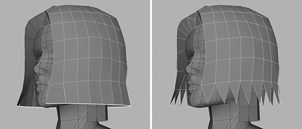
Because you did not weld the vertices on the lower areas of the strips, when you collapse the edges they will form spikes as illustrated on the right in Figure 4.13.
2. Move up to the next row of edges and, editing each one in turn, scale them in slightly. Do this for the next row, too, until you have long spikes running around her hair, as shown in Figure 4.14.

Apart from some final tweaking, our outer layer is complete. It needs additional work, moving the vertices to randomize the shape, but we won’t do that until all the basic geometry is in place. Now we must fill out the hair, making it appear thicker, giving it more volume.
3. Using the strips on the inside layer, do as you did with the outer ones. Select the bottom edges and collapse them, then adjust the upper edges until you have long, sharp polygons.
4. Duplicate these edited inner strips, creating a total of 17, and position them between the outer layer and the head.
When you’re finished working on this side of the head, you can create a mirrored version to see how the hair is looking overall. Begin by selecting all the pieces of geometry that make up the hair on Kila’s left side. Press Ctrl+G/Cmd+G to group them. Open up the Duplicate options, make sure that Instance is not selected, and click Duplicate or Apply to create a mirrored duplicate of the group (setting the Scale value for the X-axis to –1).
Kila’s coiffure should now resemble Figure 4.15. For now, the hair shape is acceptable. It still needs more work, but let’s leave it for now and go on to create the left side of the hairdo (Kila’s right). It will be different from the right side.

Developing the Left Side
The hair on Kila’s right side hangs down, but on the other side the hair is tucked behind the left ear. To start developing this side of the hairdo, first hide the inner strips so you can concentrate on the outer layer of hair (Figure 4.16).
1. Select the vertices shown in Figure 4.17b, and weld them all together until you are left with a single vertex (Figure 4.17c).

2. Move this remaining vertex up to roughly the spot where the top of the ear should be. Then proceed to work on refining this area of the hairdo until the tucked-in look is correct (Figure 4.17d).
3. Combine both the left and right sides that make up the top, outer layer of her hairdo.
4. Bring back the inner-layer strips you hid earlier, adjusting them to fit the new tucked-in arrangement. You will have to delete some of the strips that no longer fit the shape.
At this point, you have basic geometry in place to use for Kila’s hair. Keep working on it until you are happy with the overall shape.
Organizing the Strips
To keep things in order, we will now organize the strips used to fill in the hair, combining them into individual horseshoe-shaped layers. In this arrangement, not only will they be easier to work on, but applying a texture to them will be less difficult.
1. Hide everything except the strips of hair (Figure 4.18).

2. Switch to the top view so you are looking down on the strips (Figure 4.19, left). It looks like I got a bit carried away, rotating the strips to fit. First, using the Rotate manipulator, alter the rotations so the strips appear as flat lines in the top view. You will find that the same axis needs altering for each strip.
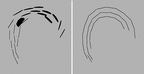
3. Position all the strips so they follow a curve, making three concentric curves in total. Add more strips if you need them to complete the curves.
4. Combine the strips that make up each curve so that you end up with three separate horseshoe-shaped objects (Figure 4.19, right).
5. Switch to the perspective view and isolate the outermost section of hair. All you should be able to see is that particular piece of the geometry (Figure 4.20, left).

6. Scale the top row of vertices down the Y axis so that they all lie on the same level. Just using the basic Scale manipulator is sufficient here because you do not need to have an exact scale. Then weld them all together, making a complete strip running around the top. Do this again for the next row down. As needed, adjust the remaining strips to tidy up the rest of the geometry. Figure 4.20 (right) shows what you’re aiming for.
7. Repeat these welding steps for the other two, inner layers until you have something close to what’s shown in Figure 4.21.

Now unhide the rest of Kila to see how things are looking. As you can see in Figure 4.22, I’ve started to shape the outer hair somewhat, by curling the ends up very slightly and refining the overall shape. Notice that I have added another strip for a loose strand at the right temple.

Refining the Hair
To complete Kila’s hair we will now spend some time working on the inner-layer strips, bending the bottoms out to follow the strands in the outer layer. We’ll also add some more volume by twisting the strips at the bottom.
Because we have been working in layers, the first step is easy. On the first inner layer, select the lower row of vertices and globally scale them outward. Move up to the next row and do the same. Continue this process on the other inner rows, curling the hair slightly outward at the bottom.
To fill the hair out a little and thicken it up, we now need to twist each strip slightly, like turning the slats of a venetian blind.
1. Select every other edge on each strip (Figure 4.23, left and middle). Then scale them across the X and Y axes, bringing them in toward the middle as shown in Figure 4.23 (right). Select only the bottom two edges of each strip; do not scale the top.

2. Repeat this process on the next layer, this time selecting the opposite edges so that the effect will be reversed.
3. Finally, scale the third layer in the same way as the first.
All the refinement work left to do now is to work on the overall shape, trying to fill in any large gaps between the strands of her hair. Take a look at Figure 4.24 to see an example of the end result.

For now, do not combine all the elements that make up the hair. Just clean up the scene and save your work as Kila_Hair.mb.
Quick Cleanup with the Outliner
If you open up your Outliner, you may notice that a lot of groups and empty nodes are starting to appear; you can also see these in Figure 4.25a. Most of these elements are unnecessary and only bump up the file size. Let’s clean them up.

1. Start by selecting in the Perspective view all the pieces of geometry you want to keep, and press Ctrl+G/Cmd+G to put them into a group. Figure 4.25b shows the new group named group3.
Tip
The easiest way to select what you want to keep is to drag a selection lasso over all of the geometry in the view.
2. In the Outliner, click and hold the middle mouse button on the new group, and move it up until it exists in the world root (that is, outside of any other groups), as seen in Figure 4.25c. As you move the group over another object, two lines will appear above and below the object; these indicate that if you let go of the mouse now, the group will be placed within this object. If a single line appears, it indicates that letting go of the mouse button here will leave the group in the world root.
3. You know that you’ve included everything you need in group3, so you can now select the other bits and pieces as shown in Figure 4.25d and delete them.
Obviously, it’s very unlikely that the items in your Outliner will exactly match the ones in Figure 4.25, but this does not matter. In deciding what can be deleted, just look for items similar to the ones highlighted that are outside the group3 group.
4. You may also notice that a few new cameras have popped up (persp1 and persp2, for example)—the result of our having imported items earlier. Select and delete these. Do not delete the four main cameras (persp, top, front, and side), but feel free to remove any others.
5. Finally, rename group3 to Kila and save.
Modeling the Ear
So now we’ve finished off the hair. Our next step is to create an ear to place on the left side of Kila’s head.
Tip
Before you start to model the ear, find a decent picture of an ear on the Internet or in an anatomy book. This will help you create an accurate model (or texture, depending on how the ear will be represented).
1. Start with a new scene, and create the cube in Figure 4.26 using the following configuration: Width 0.5, Height 1.5, Depth 1, Subdivisions Along Width 1, Subdivisions Along Height 5, and Subdivisions Along Depth 2.

2. Using your reference, shape the cube to achieve the basic shape of an ear. Work on it from the side and then the front, and finally in the perspective view until you are happy with it (Figure 4.27).

3. Before saving this version, remove some of the polygons from behind the ear, as seen in Figure 4.28.
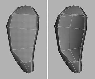
4. Delete the history and save this as Kila_Ear_01.mb, so you can use this version later if you choose.
We could quite happily use the ear in its present state, allowing the texture to show the detail—especially if we need to keep within our polygon budget. For the purposes of this tutorial, however, we will work on it a little more to show how to develop a more detailed ear in case we need one. Enhancing the ear is a simple case of cutting the details into the mesh using the Split Polygon tool, and then working on the geometry to achieve a satisfactory shape.
5. Divide the front of the ear, following the lines in Figure 4.29, left. Work on the entire front area until the ear is satisfactory (Figure 4.29, right). There is no need to put in every detail, since most of this can be achieved in the texture.

6. Delete the history and save this ear as Kila_Ear_02.mb.
Attaching the Ear
Now we have two ear models (one slightly more detailed than the other). For now, we are going to attach the higher-resolution version. When we come to optimize the mesh, we can reduce it if we need the polygons. Make sure you have both ears saved, and then load Kila_Hair.mb again.
1. Before you begin to attach the ear, you need to make the head whole. At the moment you only have one-half; the second, right side is simply an instance. Delete the instanced mesh and focus in on the head. It’s probably best to isolate the mesh, too, so you’re only working on the main body.
2. Select the faces shown in Figure 4.30 (the ones that make up the head and upper neck).

3. To separate these pieces from the main mesh, go to Edit Polygons > Extract and open up the options. Make sure Separate Extracted Faces is on, then click Extract. The head will now be separated from the rest of the body.
What we need to do now is duplicate this half, mirror it, and merge all the vertices down the center. There is a simple way to do this—use the Polygons > Mirror Geometry tool.
4. Open up the options for the Polygons > Mirror Geometry tool and, as seen in Figure 4.31, make sure –X is selected, as well as Merge With The Original and Merge Vertices. Click Mirror to apply the tool.

You should now have a full head with all the vertices welded nicely down the center; the last thing to do is smooth out the crease that runs down the middle of her head.
5. Import the ear we were working on earlier (Kila_Ear_02.mb) and position it as shown in Figure 4.32.

Looking at Figure 4.32, we seem to have miscalculated where the hair should be. We can adjust this now so that the hair lies over and behind the ear (Figure 4.32, right). Now that we know how the hair and ear should look, we can more capably work on this area. Hide the head at this stage so we can concentrate on the hair and ear.
6. As you can see in Figure 4.33 (left), one of the inner strips of hair is popping through the ear. Since this is quite close to the face, we can simply delete the entire strip by selecting its polygons and deleting them (Figure 4.33, right).

7. As illustrated in Figure 4.34 (left), rotate around so you are looking at the back of the ear from inside the head.

Tip
Press F to focus the camera on the selected object or components.
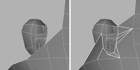
8. Snap the two vertices belonging to the hair to the two nearest ones on the top of the ear. Then work your way around, splitting the hair as shown in Figure 4.34 (right) and leaving no gaps around the top and side of the ear.
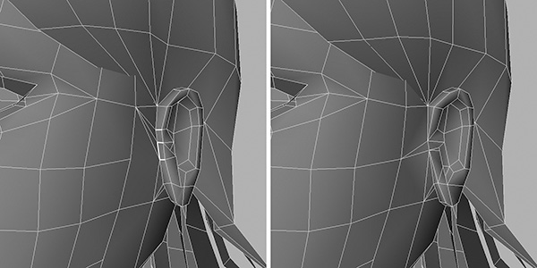
9. Bring back the geometry for the head, and hide the hair. Before using the same vertex-snapping technique to fill in the gaps between the head and ear, you must first combine them. As demonstrated in Figure 4.35 (left), look from inside the head at the ear. Use the Append To Polygons tool to fill in the gap, making a seamless join between the head and the ear (Figure 4.35, right).
10. Work on the ear until the shape is satisfactory on all sides. For a start, you can collapse the edges at the front of the ear. These are highlighted in Figure 4.36 (left). Keep working until you achieve the model illustrated in Figure 4.36 (right).
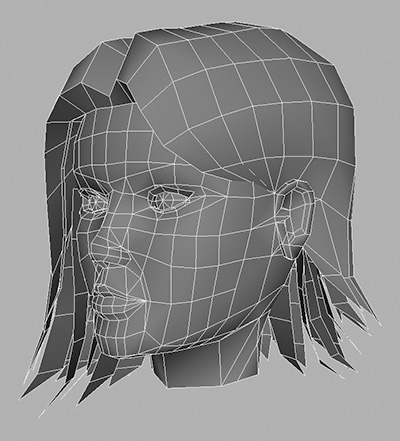
As you can see in Figure 4.37, the outer head is now complete. All we need to do to finish it is test to see how it deforms, and optimize it—both of which we will cover in later chapters.
Modeling the Eyes
If your game uses many real-time cut-scenes, chances are your character will need facial animation. The eyes play a huge part in acting; we are all drawn to the eyes when we interact with people.
Eyes are relatively easy to construct; all you need to do is create a sphere and optimize it slightly. You may have noticed that our model already has some spheres where the eyes should be. These were used earlier to create the eyelids, and we did not delete them. To demonstrate how to create the eyes, we will remove these spheres and start from scratch.
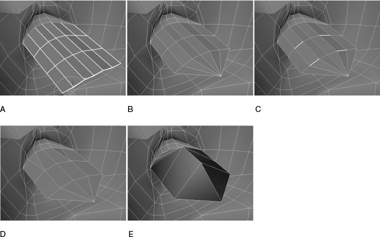
1. Create a new polygonal sphere with its Subdivisions Around Axis and Subdivisions Along Height both set to 8 (Figure 4.38a).
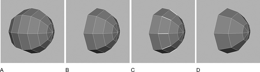
2. As demonstrated in Figure 4.38b, remove the back half of the sphere.
3. Select the edges that lie down the center of the sphere, shown in Figure 4.38c, and then collapse them to get the eye shape (Figure 4.38d).
4. Position this sphere so it lies where the left eye should be.
5. To create the right eye, duplicate the left eye mesh and alter the Translate X attribute in the Channel Box to be a negative value. For example, if it reads 0.38, make it –0.38.
There we have it; the eyes are done (Figure 4.39). Feel free to save at this point.

Developing the Inner Mouth
Cut-scenes can also involve conversation, so the inside of the mouth will need to be developed to include the teeth and a tongue. Let’s begin with her teeth.
The Teeth
Most games just adopt a simple set of teeth consisting of a flat curve of polygons with a teeth texture on them. This is what we will use for Kila—it’s unlikely that she would benefit from a set of fully modeled teeth because we will never get close enough to see them in detail. Besides, a full set of teeth would increase the polygon count dramatically.
1. In a new scene, create a new cylinder with the following configuration: Radius 1, Height 0.4, Subdivisions Around Axis 14, Subdivisions Along Height 1, and Subdivisions On Caps 1. Your cylinder should look like the one in the top panel of Figure 4.40.

2. Remove the top and bottom from the cylinder, as well as five quads from the back, giving you the shape in Figure 4.40 (bottom).
3. Teeth are never perfectly round, but at the moment our mesh is (Figure 4.41, left). Switch to the top view and scale the geometry to match the shape illustrated on the right in Figure 4.41.

4. We have our top teeth complete now. To create the bottom set, duplicate the upper set and position it below. Make sure you scale it in slightly along the X and Z axes, because a human’s bottom teeth are positioned back a little from the top teeth (Figure 4.42).
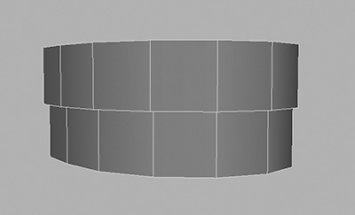
FIGURE 4.42 Duplicate the top-teeth mesh and position it underneath and slightly back from the original set.
The Tongue
Now that the teeth are done, let’s create the tongue.
1. First hide the teeth; we don’t need them yet.
2. Create a cube with the following configuration: Width 0.5, Height 0.2, Depth 1, Subdivisions Along Width 2, Subdivisions Along Height 2, and Subdivisions Along Depth 3.
3. Following the progression in Figure 4.43, adjust the shape so it takes on the look of a tongue. Scale the upper and lower vertices in slightly in preparation for the next step, in which you will move the front-center ones out a little.

4. Select the vertices that lie down the center of the object and move them down a fraction, creating the crease in the tongue.
5. Rotate the front and the back to curve the tongue.
6. Make the teeth visible again and position the tongue inside them (Figure 4.44). You may need to scale the tongue further to make it fit properly. In addition, make sure you delete the faces at the rear of the tongue, as shown in Figure 4.44 on the right.

The teeth and tongue elements are complete, so delete the history and save as Kila_InnerMouth.mb.
Adding the Inner Mouth Elements
We will next merge the inner mouth elements we created (teeth and tongue) into our character.
1. Load in the last file you were working on (Kila_Hair.mb), and import the inner mouth elements into the scene.
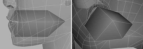
2. Scale the geometry down and position it inside her head as shown in Figure 4.45. The upper teeth should just dip down below the bottom lip.

3. Double-check the shape of the mouth. If you can see teeth popping through, then the mouth is not the correct shape. Kila’s lips should lie on top of her teeth.
The Inner Cheeks
Before we finish the mouth area, we need to do one last thing. If Kila were to open her mouth in its current state, we would see not only her teeth and tongue but also the back of her head. On some platforms, we would not even see that—we would see straight through the back of her head. What’s needed now is to create the inside of the mouth, consisting of the top of the throat (upper palette) and inner cheeks.
1. At present, Kila’s lips are sealed shut, so to start you need to cut them open. As shown in Figure 4.46 (top), focus in on her lips and select the vertices that run along the opening between the lips.

When you’re zooming into your geometry, it may happen that the camera cuts into the mesh before you get close enough. To fix this, open up the attributes for the camera by going to View > Camera Attribute Editor, and reduce the value for Near Clip Plane.
2. With the vertices selected, go to Edit Polygons > Split Vertex. This will split up the vertices, “un-welding” them, so to speak. Now the vertices are all separate. Select each one in turn and move it up or down, creating a slight opening in the mouth as shown in Figure 4.46 (bottom). Just remember to weld them again when you are done.
3. Hide the teeth and tongue for now. As illustrated in Figure 4.47, select the edges around the opening of the mouth.

4. Extrude the edges inward, adding two divisions to the extrusion (Figure 4.48a). Do this by setting Divisions to 3 for polyExtrudeEdge1 in the Channel Box.
5. Weld together all the vertices at the very end to create a point (Figure 4.48b).
6. Select the edges on both the top and the bottom of the extrusion, as highlighted in Figure 4.48c.
7. Collapse these edges (Figure 4.48d).
8. Bring the center points on the top upward, and the ones below downward, to create a hollow in the middle.
9. Optimize the shape by welding the extra vertices to the top and bottom points (Figure 4.48e).
10. Adjust the vertices to make the cavity larger. Aim for the results shown in Figure 4.49.
11. Unhide the teeth and check to see that they fit inside the cavity.
We are now finished with the head area and can move on and add some clothing. But first, clean up your scene and save your work as Kila_Head.mb.
Dressing Kila
All game characters wear some sort of outfit—more often than not these will be weird and wonderful and will require extra polygons. In Kila’s case, we have some relatively simple additions to make. These include adding details to her crop top and jeans, as well as giving her a belt and a sash that drape her waist.
Crop Top Details
We’ll enhance Kila’s crop top and chest area by adding some cleavage, as well as a suggestion of a loose overhang at the waistline.
Start with the cleavage area. In the concept drawing, the low-neck top shows a bit of cleavage. What we need to do is define the neck of her crop top to implement this cleavage.
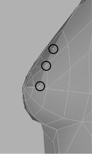
1. Using the Split Polygon tool, carve in the cuts shown in Figure 4.50 (right). These will allow us to edit the central area at the top of the cloth that bridges her breasts.

2. Smooth out the extra edges you have created—all except the ones that will mark the top of the fabric. These are highlighted in Figure 4.51 on the left.

3. Start working on the area, sculpting it to achieve the correct shape. You’re aiming for the result illustrated in Figure 4.51 on the right.
4. Move the vertices down the center first, pulling them inward, using the side view to line them up with the curve of her torso (Figure 4.52).
5. Continue working your way out, smoothing the area, moving downward the vertex just above the line of the fabric; this creates the crevice. Remember to convert joining triangles back to quads.
Notice in the concept drawing that the crop top is not skin tight, but rather is slightly loose at the bottom. We want to create this pointed “overhang.” As shown in Figure 4.53, we’ll focus in on the middle of her body.

1. Following the lines highlighted in Figure 4.54, cut around the center of the body. Mark out the base of Kila’s crop top, making sure that there are two parallel cuts encircling the entire body mesh.

2. Scale the top line out and move it down, creating the overhang seen in Figure 4.55.

3. When you created the initial cuts, some small edges will have been created; these in turn make up small polygons, like the ones in Figure 4.56 (top). It is best to get rid of these now, cleaning up the area.

4. Finally, spend some time smoothing out the general shape of the crop top (Figure 4.57).
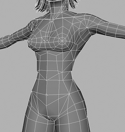
With Kila’s crop top completed, let’s continue on down to the jeans, and the sash and belt that drape her waist.
Separating the Jeans from the Body
Our next clothing task is to model the character’s jeans. We could model the left side and mirror it to create the right, as we did with her upper body. Although this would save time, it would present a few problems. First, the sash around her waist cannot be mirrored; it should be built into the waist because it fits snugly at every point from the waist to the opposite hip. Also, we will be building creases into the legs of her jeans, so it would be very obvious if we simply mirrored one side to create the other.
Before we begin, we have to separate the jeans from the rest of Kila’s body, then create a duplicate to become the right side, and combine the sides as we did for her head.
1. Delete the mirrored instance if you have one, and select the polygons that will make up the jeans (Figure 4.58). This should be easy because you marked out the top of them earlier.

2. Go to Edit Polygons > Extract; this will separate the leg from the body. You should not have to open up the options and reconfigure them because they were saved the last time you used this tool.
3. Next, you need a mirrored duplicate, so go to Polygons > Mirror Geometry. Again, you set the options last time you used this tool, so they should be at the same settings now. You don’t have to open the options.
4. Since you only need to work on her legs at this point, it makes things easier if you hide the rest of the geometry. So select everything but the legs and press Ctrl+H/Cmd+H.
5. Double-check that the vertices down the center of the legs have merged correctly. If some have not, weld them now; smooth out the crease, too.
Now we have a complete pair of legs and we can begin working in the clothing details.
Creating the Sash
Because the sash fits snugly all the way around, we can simply mark in the outline so we’ll know where it will be on her form. It is made of thin material, so we don’t need to create an overhang as we did with the T-shirt. Our task with the sash is to work on the general area, smoothing it out and tidying it up.
Use the Split Polygon tool to mark in the outline for the sash. Follow the lines in Figure 4.59. I am sure your modeling skills are coming along wonderfully now, so I will leave this part up to you. Remember to remove any tiny polygons that have cropped up, and make the area as clean as possible. Your resulting mesh should resemble Figure 4.60.


To finish the sash, we will create a couple of folds in the fabric on the outside of the leg. We can rely on the texture to create most of the folds, but these at the thigh are quite distinct, so we will build them into the geometry.
1. Following Figure 4.61 as a guide, cut the polygons around the outside of her left thigh. You’ll need two cuts for each fold. Follow these cuts around the leg, spanning two polygons, matching the cuts on the front.
2. Select the vertices on the top of each cut and move them out, creating the upper part of the fold.
3. Finally move the lower vertices up slightly to close the gap (Figure 4.61, bottom).
Creating the Jeans
Continuing on to the jeans now, we first need to get some idea of the creases in the jeans at the back of her knees, and also on the lower legs. You should have some references for this already on your style sheet. Better still, use the original color concept image (Figure 4.62). You can find this on the CD: Project Files/01/KilaColorRender.tif.

Kila’s upper thigh area is relatively flat, so we don’t need to add any detail here. Like the folds on the sash, the creases in the jeans can be added when we apply texture. We can, however, build in some folds around the back of her knees. Move down to where her knees are; use the guide images to get the correct location.
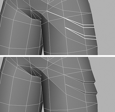
1. As you did for the folds on the sash, cut the polygons here at the knees to create two segments (Figure 4.63, left).

2. Move the top of each segment out and the lower portion up, producing the two folds you can see in Figure 4.63, bottom. Because we combined the legs earlier, you will need to do this on each knee.
Moving around to the front of her legs, we will now build in some basic knees. These will function more toward deformation than for the overall look of the mesh.
3. Cut the polygons as shown in Figure 4.64. Then pull out the upper section in the middle of the knee, creating a ridge.

4. Adjust the overall knee areas, scaling them in slightly to get the correct shape (Figure 4.65).

Now we get to the lower legs. This area needs quite a bit of enhancement to achieve realistic creases and folds.
5. Following the progression in Figure 4.66, begin by creating a cut that will be the first fold in the jeans leg. Adjust the vertices around this first cut to fold the polygons at the front over the ones at the back. Move downward, adding in one fold at a time until you reach the bottom.

6. Rotating around to the back of the leg (Figure 4.67, left), you can see that not much needs to be added here—just a few creases at the bottom will do (Figure 4.67, right).

7. Follow these same procedures for the right jeans leg, adding the extra detail to the lower leg. You can see this progression in Figure 4.68.

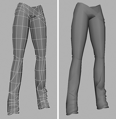
When they’re finished, the legs of the jeans should look like Figure 4.69.
After all this work, unhide everything and see how she looks. Check out Figure 4.70, left. Her feet seem wrong. They are shaped oddly; plus they are pointing forward. We want them to be pointing out slightly, as real feet do naturally.

Work a little on the shoes until they look more realistic (Figure 4.70, right) and then rotate each foot so the toes are pointing out slightly. You will also need to rotate the bottom of the jeans to match the feet.
The Belt
The belt is relatively simple. It’s essentially just a cylinder that wraps diagonally around Kila’s hips.
1. Still in the same scene, create a cylinder with the following configuration: Radius 0.2, Height 0.05, Subdivisions Around Axis 14, Subdivisions Along Height 1, and Subdivisions On Caps 2.
2. As shown in Figure 4.71, delete the central polygons; then scale the remaining vertices out to create a small rim.

3. Position the cylinder as shown in Figure 4.72. Scale and rotate it until it just fits around her hip, draping diagonally.

4. Working on the vertices, adjust the belt so it lies better (Figure 4.73).

At the point where the belt slings downward, we can actually see the inside. The problem here is that once this goes into a game engine, you may be able to see right through the belt. Because the polygons on the belt are being displayed as double-sided, we are fooled into thinking it is solid. Let’s make it single-sided and see if we get an improvement.
5. Select the belt and press Ctrl+A to open up the object’s attributes (Figure 4.74).

6. In the Render Stats pane, uncheck the Double Sided option; this will show you how the belt will look when it is displayed single-sided, as will happen in some platforms (Figure 4.75, left).

7. Using the Append to Polygon tool, fill in the gaps on the inside of the belt (Figure 4.74, right)—but only do this at the base. The rest of the belt should lie quite close to the character’s body, so we don’t need to do the rest.
And there we have it; our model of Kila is complete! You can see the finished model in Figure 4.76.

You can clean her up as we did before, by deleting the history. In addition, at this point you can also freeze the transforms. This will reset all translate and rotate values to 0 and all scale values to 1, without losing any of the position, rotation, scale, or pivot alterations done to the mesh so far.
Save the file as Kila_Complete.mb.
Although we’re done working on this latest version of Kila, we have two more stages to go through before she can be signed off. In Chapter 5, we will examine optimization tasks, and in Chapter 6, we will look at deformation.
Summary
We now have a complete model of Kila, our main character. She has all the detail we need at the moment—but this also means we may have gone over our polygon budget. In the next chapter, we will examine areas where we can optimize, removing any geometry that is not needed.