
Chapter 8. Texture Preparation
CD Files
CheckerMap.jpg
Kila_DeformTest.mb
Kila_Divided.mb
Kila_Mapped.mb
Grae_DeformTest.mb
Grae_Divided.mb
Grae_Mapped.mb
KilaBodyUV.tga
KilaHairUV.tga
KilaHeadUV.tga
GraeBodyUV.tga
GraeMiscUV.tga
GraeWingUV.tga
The kila and grae models are complete, but they need color to bring them to life. Before we can apply color to our geometry we must prepare the surface by applying UV data.
Within each vertex that exists in your polygon model lies a UV point (“UV” for short), which stores 2D coordinates that correspond to specific pixels on your texture. When you create any primitive objects in Maya, UVs are assigned by default, but these UVs are often altered when further modeling occurs—meaning that they need to be rearranged to look correct.
We will begin this chapter by looking at ways to clean up the UV data, making it usable so that we can then apply a texture to our characters.
Mapping Methods
There are four main ways to apply UV mapping data to a polygon object: planar mapping, cylindrical mapping, spherical mapping, and automatic mapping. All of these involve projecting the data directly onto the objects surface.
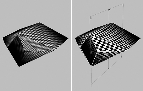
Planar mapping (Edit Polygons > Texture > Planar Mapping) projects UVs through a plane along one direction only onto a mesh. This method is ideal for mapping flat objects.
As you can see in Figure 8.1, the front of the cube is mapped fine, but because we are using a planar map the texture is stretched along the sides. To fix this you would need to apply additional mapping to the other five sides.

Cylindrical mapping (Edit Polygons > Texture > Cylindrical Mapping), as the name implies, projects the UVs inward through a cylinder onto the selected object (Figure 8.2). This will work best on the outer polygons but, as with the planar mapping, you will need to add further mapping to correct the top and bottom caps.

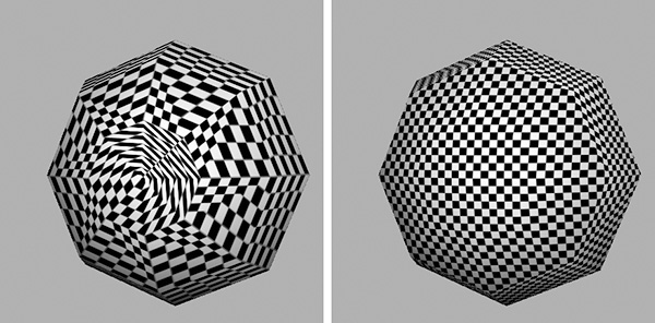
Similarly, spherical mapping (Edit Polygons > Texture > Spherical Mapping) projects inward through a sphere (Figure 8.3).

The three techniques mentioned so far have very similar options for altering the final projection. Let’s have a look at some of the more common options, shown in Figure 8.4; these are for a planar projection but are also used on the other projections.
![]() Keep Image Ratio will lock the aspect of the projection to that of the image you are applying it to.
Keep Image Ratio will lock the aspect of the projection to that of the image you are applying it to.
![]() Smart Fit will automatically fit the projection to the geometry. If turned off, the projection manipulator will be created at the world root.
Smart Fit will automatically fit the projection to the geometry. If turned off, the projection manipulator will be created at the world root.
![]() Mapping Direction is a setting unique to a planar projection and the one you will use most often. This allows you to dictate which axis the projection should come from.
Mapping Direction is a setting unique to a planar projection and the one you will use most often. This allows you to dictate which axis the projection should come from.
![]() Image Center, Image Rotation, and Image Scale each adjust the position, orientation, and size of the projection.
Image Center, Image Rotation, and Image Scale each adjust the position, orientation, and size of the projection.

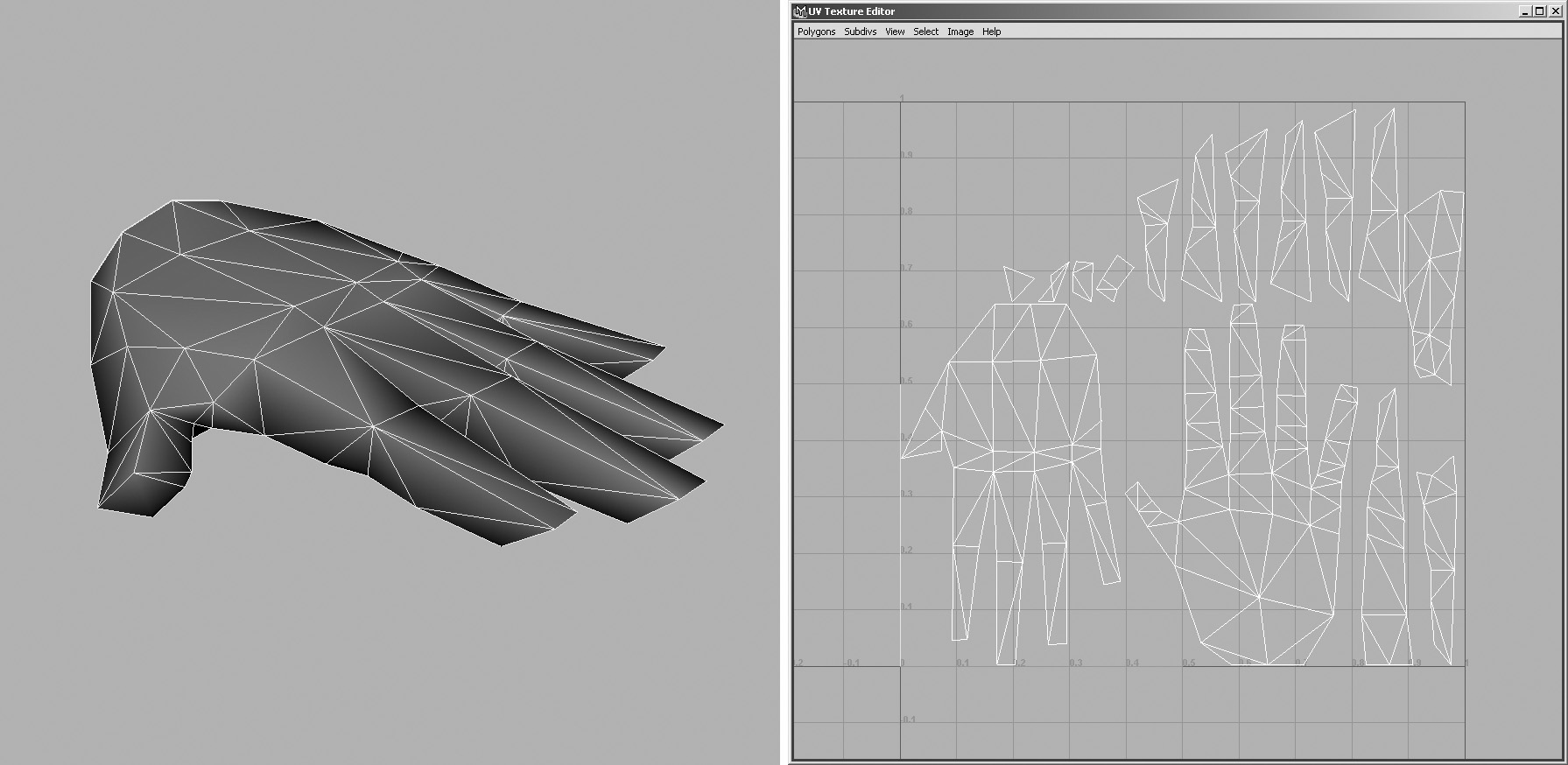
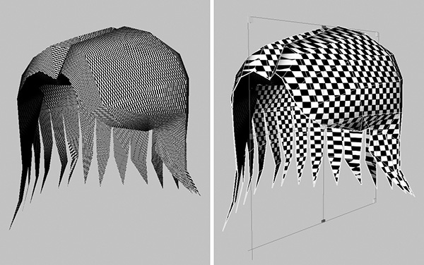
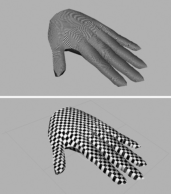
The fourth and final mapping method is automatic mapping (Edit Polygons > Texture > Automatic Mapping). This will attempt to find the best UV layout for your mesh by projecting inward from a specified number of angles.
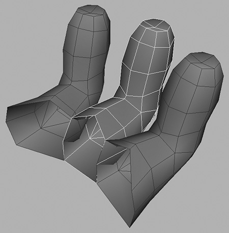
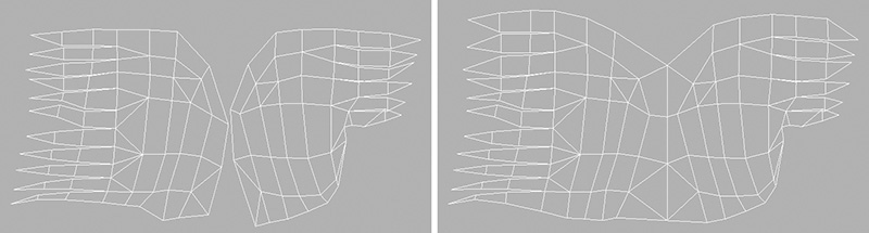
Look at Figure 8.5, left, where we have a basic, low-polygon hand model. If we apply automatic mapping with the default options, our UVs will be laid out for us. You can see this in Figure 8.5, right.
Note
To see an object’s current UV layout, simply select the mesh and go to Window > UV Texture Editor. In addition to seeing the UVs, you can also edit them; we will talk more about the UV Texture Editor later in the chapter.
We will see how to use some of these mapping methods as we apply UV mapping to our characters, but first we need to prepare the geometry to make the mapping process easier.
Dividing a Character
The most efficient way to texture a character is to divide it up into areas whose shapes lend themselves to a particular type of projection. For example, an arm could either be treated as a cylinder, or if divided lengthwise, could use two planar projections. The idea is to approach the mapping procedure with a strategy.
Here is what to look for when choosing how to break up the character:
![]() Look for areas that resemble the projection shape most closely. If you map a cylinder with, say, a planar projection, you will wind up with stretching on two sides and overlap on the back; overlap is bad in almost all cases.
Look for areas that resemble the projection shape most closely. If you map a cylinder with, say, a planar projection, you will wind up with stretching on two sides and overlap on the back; overlap is bad in almost all cases.
![]() Look for areas that can share the same texture and projection information. The left and right side hand areas, and maybe even the pants legs or the face (if symmetrical) are likely candidates.
Look for areas that can share the same texture and projection information. The left and right side hand areas, and maybe even the pants legs or the face (if symmetrical) are likely candidates.
![]() When choosing where to cut, try to hide seams wherever possible. Look first for natural seams like waistbands and collars. If there is no natural seam, choose the next least conspicuous spot, such as under the armpit, between legs, under hair, and so forth.
When choosing where to cut, try to hide seams wherever possible. Look first for natural seams like waistbands and collars. If there is no natural seam, choose the next least conspicuous spot, such as under the armpit, between legs, under hair, and so forth.
Splitting the geometry up will make it easier to apply the initial UV projections to the character. With these in place, we can then go in and tweak the UVs individually to reduce any undesirable stretching and overlap.
We will now begin working on Kila to show how best to divide her. No mapping will be applied at this stage.
Kila
Load the file called Kila_DeformTest.mb.
Note
It’s been a while since we looked at the Kila model because we have been working on Grae. Take this opportunity to have a fresh look at the model, making sure you are happy with it. When you’re ready, we will begin by examining the torso and arms.
Torso and Arm Preparation
Kila currently only has one-half of her upper body; the entire right side is a mirrored instance. We’re going to delete the instance and create a mirrored copy of the left torso for her right side—but first we will extract her arm. We do this because although we want to map then entire torso, the mapping for her left and right arms can initially be the same, so we only need one arm to exist at this time.
1. Select the faces that make up Kila’s left arm and extract them, separating the arm from the torso (Figure 8.6).

2. Now we can go in and finish preparing the torso. First delete the mirrored instance, so only the left half of her torso remains.
3. Use the Polygons > Polygon Mirror tool, making sure Weld Vertices is enabled. This will create the right side.
4. If the vertices running down the center of her torso did not all lie on the same plane when you did the mirroring step, you may need to go in now and make sure that they are welded correctly. When that’s done, smooth the edges.
We now have a complete torso that is almost ready for mapping. There are two ways to approach this area:
![]() It’s basically cylindrical in shape, so we could map it cylindrically. This would produce a good result, but it can be difficult to control the positions of the seams. (The seams are the areas where the cylinder edges meet. If you imagine rolling a piece of paper around your arm, this is the cylindrical projection. The position of the seams will be the places where the edges of the paper meet.)
It’s basically cylindrical in shape, so we could map it cylindrically. This would produce a good result, but it can be difficult to control the positions of the seams. (The seams are the areas where the cylinder edges meet. If you imagine rolling a piece of paper around your arm, this is the cylindrical projection. The position of the seams will be the places where the edges of the paper meet.)
![]() We could detach the front and back, planar-mapping both. This would give a better UV layout. We’d only have to adjust the sides and the breast area because they will initially overlap and be stretched.
We could detach the front and back, planar-mapping both. This would give a better UV layout. We’d only have to adjust the sides and the breast area because they will initially overlap and be stretched.
Another advantage to splitting the torso would be the placement of the UV seams. They would run down Kila’s sides, so we could disguise them as the seams on her T-shirt. In addition, they would also be hidden when her arms are down, which would be for the majority of the time.
Planar mapping seem to be the best option, so let’s now split the torso in two.
1. Select the faces that make up Kila’s front, selecting the ones that face forward more than backward. Use Extract to separate them (Figure 8.7).

The front and back are now separated and prepped, ready to be mapped.
We will apply cylindrical mapping on the arm, because the shape is almost cylindrical and it will give us an opportunity to see this form of projection demonstrated. Alternatively, you could apply the same technique that we used for the torso, as we will with the legs later. The hand, however, will need planar mapping to both the top and bottom, so that we can apply a different texture to each side.
2. Start by detaching her hand from the arm. Select the faces that make up the hand and Extract them (Figure 8.8).

3. Finally, separate the top of the hand from the bottom (Figure 8.9).

The torso, arm, and hand are now ready to be mapped. Let’s continue down her body now and work on the legs.
Leg Division
For Kila’s legs, we can adopt the same technique we used on the torso. Her jeans will have a seam that runs down the outside and the inner leg; this can be used to disguise the UV seam.
As you did with the torso, select the front faces (Figure 8.10) and Extract them.
Shoe and Belt Division
Continuing on, we get to the shoes. Both shoes will be mapped the same, so we can delete the one on the right for now, and duplicate the left shoe once mapping has been applied.
There are a number of ways you can approach the shoes, depending on the amount of detail you wish them to have.
![]() A simple planar projection from the side is usually a good way of quickly mapping the shoe. This does mean, though, that the inner and outer sides of the shoe have to be the same.
A simple planar projection from the side is usually a good way of quickly mapping the shoe. This does mean, though, that the inner and outer sides of the shoe have to be the same.
![]() You could use automatic mapping, as demonstrated earlier with the hand model, but this might give unpredictable results—you could wind up spending most of your time rearranging the UVs.
You could use automatic mapping, as demonstrated earlier with the hand model, but this might give unpredictable results—you could wind up spending most of your time rearranging the UVs.
![]() To get the most detail into the shoe, the best approach is to manually split up the model. This will also give you more control over the UVs’ placement. This is the method demonstrated in this discussion.
To get the most detail into the shoe, the best approach is to manually split up the model. This will also give you more control over the UVs’ placement. This is the method demonstrated in this discussion.
Separate the sides, top, front, back, and bottom (Figure 8.11). We will apply planar mapping to each area later.
Leave the belt intact, since it was created from a basic cylinder that has not been altered enough to destroy its initial mapping coordinates.
With separation of the main body completed now, let’s see what needs to be done to her head.
Head Division
The main head will be fine as it is; a simple cylindrical or planar map will work well here. So let’s concentrate on the inner mouth, along with her eyes, teeth, and tongue.
1. Detach the inner mouth (Figure 8.12) and the ear (Figure 8.13). We do this because both these areas can initially be planar-mapped.
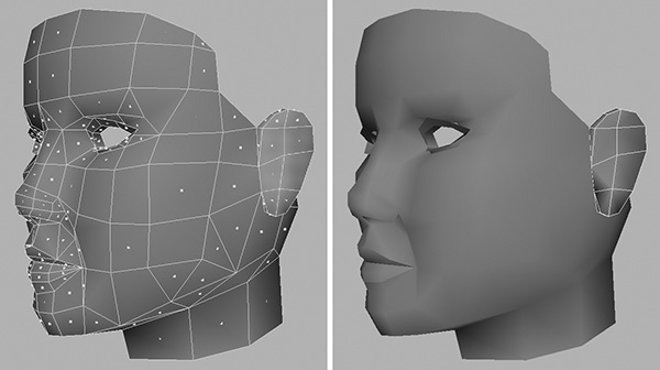
The inner mouth will need only a simple texture, perhaps a gradient running through it. The ear will benefit from a simple planar projection.
2. Both the eyes will be handled the same, so delete the one on the right side.
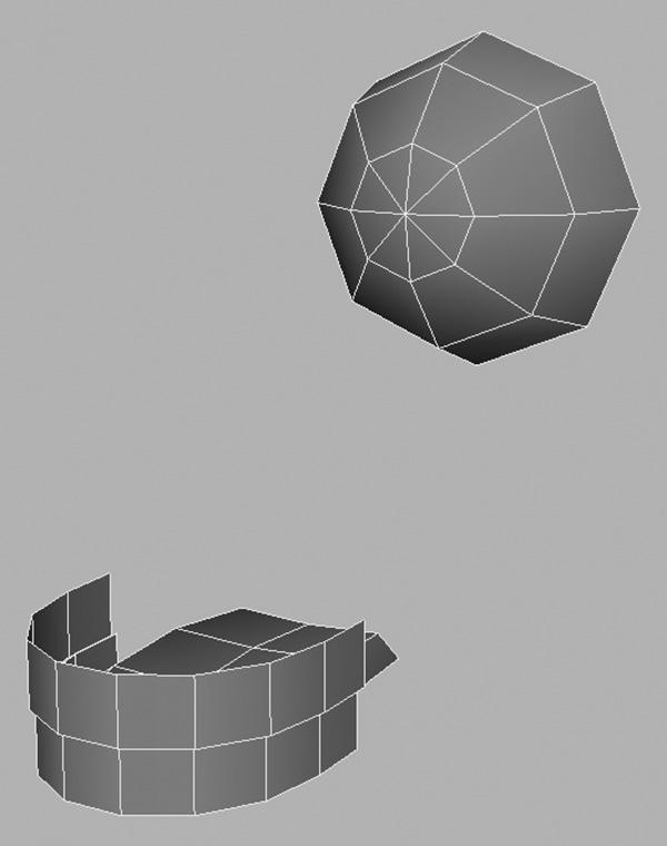
3. We don’t need to do anything to the teeth. Like the belt, the teeth were created from cylinders and so should still retain some good mapping. You can also leave the tongue as is, because it’s a basic shape (Figure 8.14).
Hair Division
The inside layers of Kila’s hair were initially made from individual strips of polygons. Therefore, this part of the hair should retain its basic mapping—if we texture one strip with particular mapping coordinates, they will exist in the other strips.
Using this method will save texture space and, since the inner layers are not fully visible, we should be able to get away with repeating the texture. If, on the other hand, the texture looks obviously copied, we can apply a cylindrical map to the layers.
The outer layer of hair is a different story. No usable mapping exists on it because we have drastically edited the topology. But we only need to do a couple of things to prepare the hair.
1. The best approach for the outer hair is to first split the hair down the middle, as shown in Figure 8.15.

2. Separate the inner polygons from both sides (Figure 8.16).

Kila is now prepped and ready to be mapped. Clean up the geometry by deleting the history, and save the file as Kila_Divided.mb.
Grae
Grae is a more unique character than Kila, but a lot of the same principles will apply. We will now take the same steps with the Grae model, getting him ready to apply UV mapping.
Start by loading the file named Grae_DeformTest.mb. As you did with Kila, take some time to check the model for any last-minute changes.
Wings
We will initially hide the wings and concentrate on the main body of Grae.
You may be thinking that we could delete a wing, mirroring the other one across. We could do this with ordinary wings because the mirroring would not be obvious. However, Grae’s wings are made up of tendrils and should not look identical. What we can do is leave the wings until last, applying them to a separate texture page. Then we can judge whether we have the space to map both separately.
So for now, go ahead and divide up the body.
Leg Division
With the wings hidden, the first area of Grae’s body that stands out are his legs. Looking back to our concept drawing, we can see that the upper thigh sections differ in surface design and thus will each need separate mapping. The lower legs, however, are the same, which allows us to use identical mapping techniques.
1. As shown in Figure 8.17, detach the lower legs and delete the one on Grae’s right.
2. Because all three toes were initially created out of the same piece of geometry, we can delete the outer two and concentrate on the central one. Detach all three toes from the main foot (Figure 8.18), separate the toes, and delete the outer two.
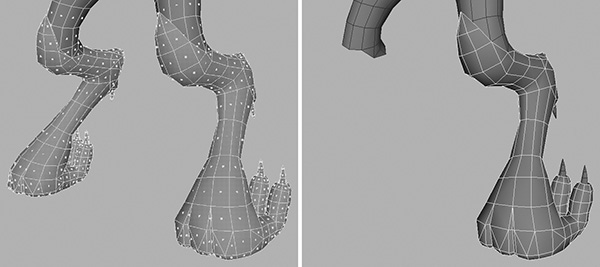
3. As is, the lower leg section is too complex to achieve clean mapping; breaking it up will simplify the process. Detach the lower section of the leg, as shown in Figure 8.19.
The lower legs can be cylindrically mapped, leaving the upper thighs to be mapped with the torso, so let’s look at that area next.
1. Select and detach the arms (Figure 8.20). This will leave us with the main area we want to work on.

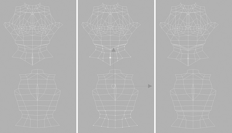
2. We can map Grae’s upper body and thighs much the same way as Kila’s torso. Separate the front and the back (Figure 8.21) so you can later apply planar mapping to them.

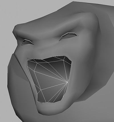
3. Detach the head (Figure 8.22) and then the inner mouth (Figure 8.23). You could split the head down the center, mapping one half and mirroring it. In this case, though, leave the head intact, because the texture may need to be different on each side.

4. Separate the upper and the lower teeth so that you can map them independently (Figure 8.24).

Note
Because the upper and lower teeth aren’t physically connected, you can simply go to Edit Polygons > Separate to detach them.
This is all we need to do to the upper body area for now, so now let’s edit the arms.
Arm Division
Start with the left arm.
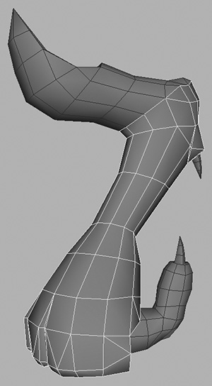
1. Following Figure 8.25, first detach the hand and then the upper arm. (The arm itself is bent much more than Kila’s was. Detaching it will make it easier to map.)

2. Separate the spikes from the upper arm (Figure 8.25, right), since these can be mapped separately.
3. Moving on to the right arm, divide it up into the same workable sections.
4. To finish up, divide both hands into top and bottom sections.
Grae is now divided and ready to be mapped. Save the file as Grae_Divided.mb.
With both models prepared, we can move on to apply mapping to Kila and Grae. We will use tools already mentioned in this section, as well as get our first introduction to the UV Texture Editor.
Mapping UVs: The Checker Map Technique
Using a checkered texture as a guide while you manipulate the UV coordinates on your mesh will make it very obvious when an area gets stretched or looks distorted. Once you’ve corrected all these problems, you can create your texture safe in the knowledge that what you draw is what you will see on your geometry. The checkered technique is also a good way to visually verify that all areas of the model are receiving proportionally comparable texture space relative to each other.
Create the Checkered Texture
Load in the file Kila_Divided.mb.
Before we edit the UVs, we need to see how they currently lie on the geometry. To do this, we’ll first create the checkered material that will be applied to the model.
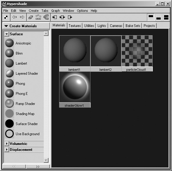
1. Go to Window > Render Editors > Hypershade. This opens the window in Figure 8.26. Hypershade contains all the information on your current materials and textures, as well as on various other objects such as lights and cameras in Maya.

Note
By default the Hypershade will open with split view, the top shows the current shaders in the scene and the bottom is a work area. This is useful if your scene has lots of materials, as you can drag individual shaders into the work area for closer attention. To change the Hypershade view, use the three boxes to the far right of the Hypershade toolbar, Show Top Tabs Only, Show Bottom Tabs Only, and Show Top and Bottom Tabs.
![]() An Anisotropic material is used to represent surfaces that have small grooves, like brushed metal or a vinyl record.
An Anisotropic material is used to represent surfaces that have small grooves, like brushed metal or a vinyl record.
![]() A Blinn material is useful for shiny, metallic-looking surfaces.
A Blinn material is useful for shiny, metallic-looking surfaces.
![]() A Lambert is a material that represents flat, matte surfaces.
A Lambert is a material that represents flat, matte surfaces.
![]() A Layered Shader is used when you want to combine two materials or textures into a single material.
A Layered Shader is used when you want to combine two materials or textures into a single material.
![]() Phong and Phong E materials are useful for shiny, plastic-looking surfaces.
Phong and Phong E materials are useful for shiny, plastic-looking surfaces.
2. We don’t need a shiny finish to this texture, so we will use a Lambert. There are a couple of ways to create this:
![]() Select Create > Materials > Lambert either from the Hypershade menu bar or by right-clicking
Select Create > Materials > Lambert either from the Hypershade menu bar or by right-clicking
in the main window and using the contextual menus.
![]() Select the Lambert icon under the Create Materials bar on the left. (If this bar is set to something else, like Create Textures, click the name and select Create Materials from the drop-down menu.)
Select the Lambert icon under the Create Materials bar on the left. (If this bar is set to something else, like Create Textures, click the name and select Create Materials from the drop-down menu.)
Whichever method you choose, the result is a new material called lambert2 (Figure 8.27).
3. Double-click the new material to open its attributes, as shown in Figure 8.28.

4. Highlighted at the top of the window in Figure 8.28, in the lambert text field, is its current name. Change lambert2 to Check.
5. Under the Common Material Attributes section you will see various options, from Color to Translucence Focus. We are only interested in the Color option for now.
Next to this is a colored rectangle and then a slider, and a small box with a checkered pattern in it. Click this box to open up a Create Render Node window (Figure 8.29).

6. Under the heading 2D Textures, select File. The Attribute Editor now changes to show the file’s attributes (Figure 8.30).
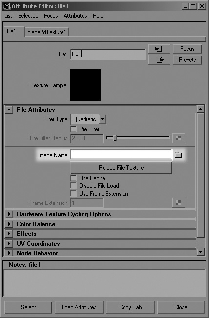
7. Next to Image Name, you’ll see a space followed by a folder icon. Click this folder and browse to the file called CheckerMap.jpg (you can find this file on the CD in Project Files/08).
8. Click Close to complete the material’s creation. Go back to the Hypershade; as you can see from Figure 8.31, the material is now named Check and the ball shows the checkered texture that is applied.

9. Before we apply this material to Kila, we need to make materials visible in the view panels. Go to the Shading menu and make sure Hardware Texturing is on, or press 6 on your keyboard.
10. The quickest way to apply the Check material to our character is to select all the geometry, then right-click the material in the Hypershade and select Assign Material To Selection. Make sure to right-click only the material—there is no need for it to be selected (highlighted) in the Hypershade. Left-clicking to select it first will only serve to de-select the geometry.
Another method is to middle-mouse-button-click your material and drag it to the geometry to which you want to apply it.
Your model now looks like the one in Figure 8.32. You can tell that the UVs need work at this stage, because the grid is not cleanly laid out over her body. With the material applied, we can now go in and tweak the UVs, making sure the squares on the texture are lined up correctly.

Arm UVs
Let’s begin our UV work with Kila’s arm. Since the shape is cylindrical, we can simply apply a cylindrical map to this area. The problem is that since her arm is bent, a single cylinder will not suffice. So we will map her upper and lower arm separately, as shown in Figure 8.33.

1. Select the faces of the upper arm (Figure 8.33b).
2. Go to Edit Polygons > Texture > Cylindrical Mapping, to apply the mapping to the selected faces.
You are now presented with the projection manipulator; you can see it in Figure 8.33c. This represents how the mapping is being applied to the geometry and, like any other manipulator in Maya, you can adjust it to better suit your needs:
![]() The small light-blue squares in the corners manipulate the projection’s height and horizontal sweep.
The small light-blue squares in the corners manipulate the projection’s height and horizontal sweep.
The horizontal sweep is the amount by which the projection wraps around an object. The default amount is 1.8, which is 180 degrees and only covers half the object. This doesn’t mean, however, that only half of the object is mapped; it merely alters the aspect ratio of the UV placement. You can edit the horizontal sweep directly by moving the red squares on either side of the manipulator.
![]() The green squares adjust the height of the mapping, and the light-blue flat square in the center adjusts its overall scale.
The green squares adjust the height of the mapping, and the light-blue flat square in the center adjusts its overall scale.
![]() The last, larger cyan cube, which exists on the edge of the projection, adjusts its rotation around the object.
The last, larger cyan cube, which exists on the edge of the projection, adjusts its rotation around the object.
These handles are all good for adjusting the projection locally—but what if you need to move it globally? You should see a red T icon in the bottom-left corner of the projection manipulator. Selecting this will toggle between the projection’s default manipulator and Maya’s standard Translate/Rotate/Scale manipulator (Figure 8.33d).
We now need to adjust the cylinder’s manipulator so that it fits this portion of her arm.
3. Start by using the red cubes to adjust the horizontal sweep, making the projection spread around to the back of the arm.
4. Click the T icon to switch to Maya’s default manipulator and use this to adjust the cylinder’s rotation so it matches the orientation of the upper arm (Figure 8.33e).
5. Now you can either use the current Scale manipulator, or click the T icon again to return to the projection manipulator and adjust the scale to envelop the arm.
6. With everything still selected, go to Window > UV Texture Editor.
The UV Texture Editor (Figure 8.34) shows how the UVs of the currently selected object are laid out. What you see is the upper arm flattened out, as if you have peeled the skin off and laid it out flat—in other words, “unwrapped.” Here is where we will manipulate the UVs, adjusting them to eliminate undesired overlap, reduce stretching, and make the UVs easier to paint.
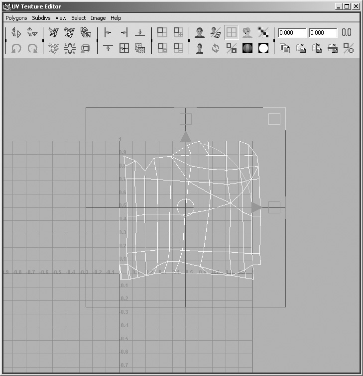
You may still have the actual Check texture in the background. This texture is usually good to use as a guide, but for now we need to remove it. Turn off the image by going to Image > Display Image.
The upper arm is looking okay now. The UVs are nicely laid out following a uniform pattern. We can also identify key areas of the arm, such as the shoulder, which will be useful when we paint our textures.
Let’s continue on now to work on the UVs of lower arm. Select the faces for the lower arm and repeat the foregoing procedure (Figure 8.35).
Note
It is important that the projection manipulator’s orientation around the mesh matches that of the upper arm. This will ensure that both sets of UVs will follow the same lines when we come to edit them; for example, we want the elbow’s UVs to line up.
The basic UV mapping is now in place for the arm, but we need to work on it some more before we are finished.
UV Manipulation on the Arm
With the basic mapping in place, we can now edit the UVs in the UV Texture Editor.
1. Select the arm and look in the UV Texture Editor. You can see in Figure 8.36 (left) that both sets of mapping overlay each other. We need them to be separate.
2. In the perspective view, select the faces of the upper arm. They will be highlighted in the UV Texture Editor.
3. Move back to the UV Texture Editor and go to Select > Convert Selection To UVs. Both sections of the arm will be visible once more, but only the UVs for the upper arm will be selected (Figure 8.36, middle).
4. Press W to switch to translate mode, and move the selection up, separating the two sets of UVs (Figure 8.36, right).
Now the UVs are separated so we can see them clearly. We next need to combine both sections of the arm, making one complete piece and eliminating the seam between the upper and lower arm sections.
UV Sewing
Since the upper and lower arms are already combined in the 3D view, connecting them in the UV Texture Editor is simple.
1. Right-click in the UV Texture Editor and select Edge from the marking menu, putting you into edge-selection mode.
2. Select one of the edges at the base of the upper arm. You will notice that the edge it is connected to in the 3D view is also highlighted in the UV Texture Editor, and its associated edge along the border of the other set of UVs is highlighted.
Note
If the two edges do not lie above and below each other, right-click and select UVs; then move the upper arm UVs along until the edges match.
3. Holding the Shift key, continue across until you have the bottom row selected, as shown in Figure 8.37 (left).

4. To weld these edges together, go to Polygons > Sew UVs.
We now have one complete map of UVs unwrapped for the arm (Figure 8.37, left).
UV Cutting and Moving
Look at the UVs of the arm; you will notice an area that sticks out to the left. This needs to be cut off and positioned in the gap on the right, making the UV map clean and easier to read.
Note
Depending on how your mapping went, this projection may be severe, but don’t worry—the next steps will help you fix this.
Let’s first check and see where the seams lie. Select a UV on the border in the UV Texture Editor; this will also show up in the 3D view, letting you see where the seam is. We want the seam to be on the bottom of the arm, so that when the arm is lowered, the seam is not as noticeable. Currently the seam is around the back of the arm, across the elbow.
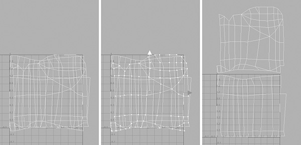
We have two problems to solve here. We will first cut the UVs where we want the seam to be, moving the remainder over to the right before sewing them again. The following steps are illustrated in Figure 8.38.

1. In the UV Texture Editor, select a line of edges from the top to the bottom. These will mark the underneath of the arm (Figure 8.38a). To find this line, go to your 3D view and switch to UV editing mode. Then select a UV under the arm; this will also show up in the UV Texture Editor, so you can tell what edges to select.
2. Now you know where to cut, so go to Polygons > Cut UVs.
3. Still in the UV Texture Editor, switch to face-editing mode and select the faces to the left of the cut (Figure 8.38b).
4. Go to Select > Convert Selection To UVs so that we can edit this piece (Figure 8.38c).
5. Move the selection over to the right. This should fit more or less exactly (Figure 8.38d).
6. Finally, select the edges where the new join is and go to Polygons > Sew UVs to join them (Figure 8.38e).
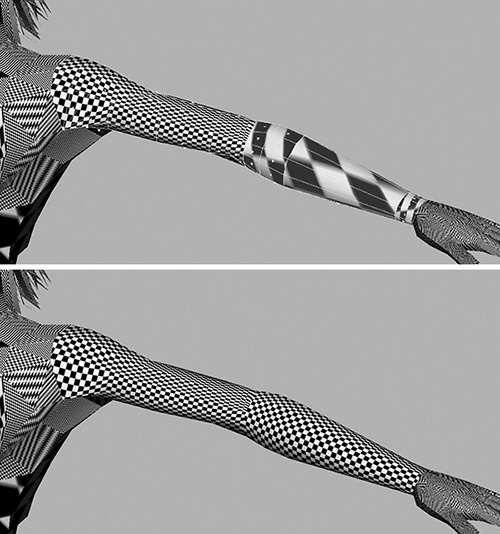
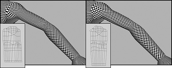
Now comes the fun part. We have our basic UV map showing us an unwrapped version of the arm. The problem is that some areas are still stretched and do not fit correctly. We’re going to edit the UVs individually in the UV Texture Editor, trying to get the grid on the arm as perfect as possible.
The checkered texture works well as a guide. Try to keep the squares square and proportionate (Figure 8.39). This can be a tedious job, but when the UVs are correctly laid out, your texture will not stretch or look incorrect. Once you have spent time painting the texture in Photoshop, the last thing you want is for it to appear warped on the actual geometry.
Note
Keep in mind that you will not be able to remove all of the stretching from the texture. I suggest that you concentrate on the larger areas that will hold detail. The main forearm, elbow, and shoulder will be most visible, whereas the underneath part of her arm won’t be seen most of the time.
The arm is done; let’s get to the torso UVs.
Torso UVs
We will approach the torso from a slightly different angle, this time we will begin by planar-mapping the front and back before tweaking the UVs in the UV Texture Editor.
1. Select the front and go to Edit Polygons > Texture > Planar Mapping. Make sure Keep Image Ratio is checked in the options box; this will initially keep the squares in your texture at the correct size. Your torso will now be mapped (Figure 8.40, right).

2. Flip around to the back of the torso and apply the same mapping with the same configuration (Figure 8.41).
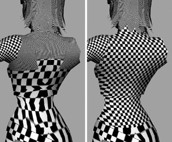
3. Although these areas look fine when you’re looking at them straight on, the sides are stretched. Work on the front first, editing the UVs in the UV Texture Editor (Figure 8.42). Make sure no UVs overlap, particularly around her chest and armpit areas.

4. When we applied the mapping to Kila’s back, it was projected from the front, so in effect the UVs are mirrored. Before you begin editing here, we need to flip all the UVs. Select them all in the UV Texture Editor and go to Polygons > Flip UVs, making sure you select Horizontal in the options.
5. Now work on the back, removing most of the stretched areas of the texture until it resembles that in Figure 8.43. Try to remove as much as you can here, because Kila will eventually have a tattoo; if the UVs are incorrect, the tattoo will stretch.

The UVs are now nicely laid out for her torso. Next up is the lower body, including waist area, legs, and feet.
Lower Body UVs
To make it easier to generate the texture for Kila’s sash and the jeans, we will keep the waist and leg UVs together.
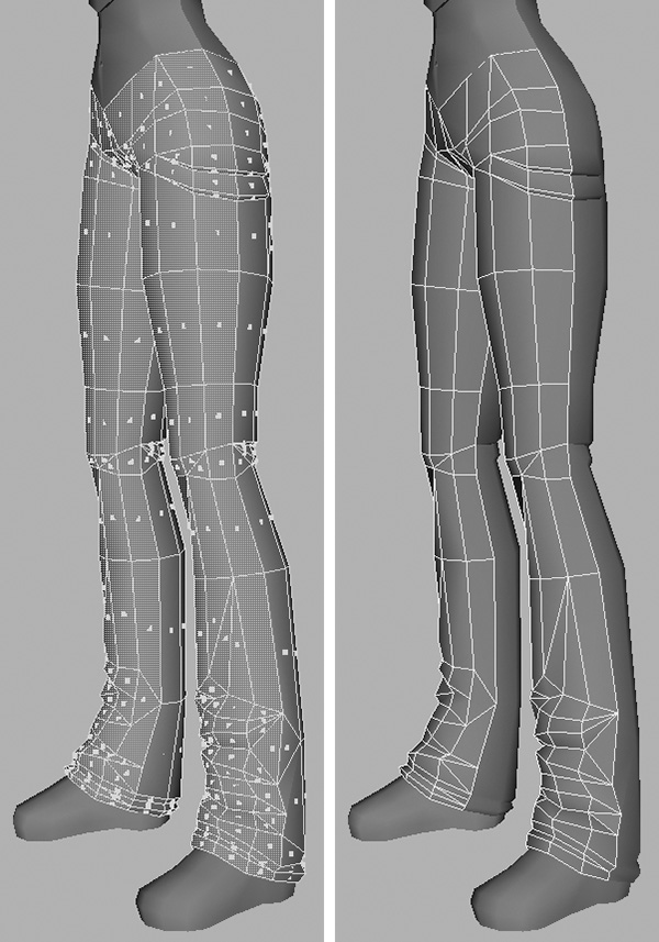
Waist and Legs
The UVs for the waist items and the legs will be edited exactly the same as you did her torso. Let’s start with the legs.
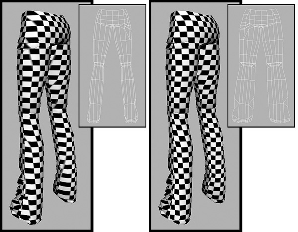
1. As seen in Figure 8.44, first apply planar mapping to the front and the back of the entire lower body.

2. Using Figures 8.45 and 8.46 as a guide, edit the UVs in the UV Texture Editor. Your goal is to reduce the amount of stretching that can be seen. Remember to flip the UV’s for the back of her legs before you edit them.

Feet
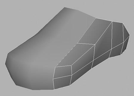
The feet are already split into six segments, ready for mapping. You should have front, back, left, right, top, and bottom segments.
Note
As mentioned previously, simple planar-mapping of the foot from the side will provide a good enough UV layout for you to texture, because most shoes are identical on both sides. You will then just separate the base of the foot and map this separately in order to apply the tread on the sole. Creating the UVs for the shoe, as demonstrated in this section, should be reserved for feet that hold a lot of texture detail.
1. Select each portion of the foot and apply Planar Mapping to them all individually (Figure 8.47). Remember to set the Mapping Direction in the options; this will save you time when you are adjusting the projection.

2. Select all the pieces of the foot and look at their mapping in the UV Texture Editor (Figure 8.48a).

3. The UVs for each piece are overlapping, so, working on each piece individually, select the UVs and move them out of the center, as in Figure 8.48b.
4. When they are all moved, you can combine the geometry that makes up the foot. Remember to weld the vertices as you do.
5. With the foot once again a whole object, edit the UVs some more, sewing the sides and front to the top (Figure 8.48c). Make sure all the pieces are the correct size—remember that you will end up with more detail on areas that are larger.
As you can see in Figure 8.48d, with the UVs manipulated the foot looks a lot cleaner.
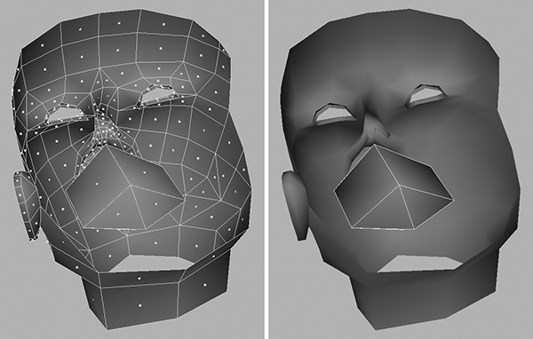
Head UVs
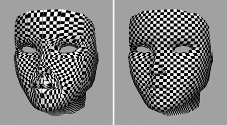
The head is relatively simple to map. As you can see in Figure 8.49, starting with a basic cylindrical map will give us a good starting base.
Kila’s eyelashes are going to be solid black, so we will map them separately. If we need to later, we can adjust these UVs so we can apply additional detail.
1. Select the faces that make up the eyelashes, as shown in Figure 8.50 (top).
2. Because the eyelashes are a basic black, we don’t need them to have separate UVs; they can occupy the same space on the texture page. And they won’t have any detail, so we can afford for them to use just a small area of the page. So go ahead and apply a basic planar map to them, projecting from the X axis (Figure 8.50, bottom).
3. While you still have the eyelashes selected, go to the UV Texture Editor window, change the selection to UVs and move them up so they will be above the head.
Figure 8.51 shows the head UVs in their current state. As you can see, the eyelashes are now separate and above the head.

Let’s stay in the UV Texture Editor and work directly on the UVs for the face. The actual geometry of the face has the eyes open, but in the UV layout they should be closed so that we can apply a texture to her eyelids.
4. As seen in Figure 8.52, manipulate the UVs so that the eyes appear to be closed.

Next, you will separate her lips. This will give them nice clean edges, making the texture appear higher in resolution than it actually is. Secondly, it will let you give the lips a larger area on the texture page so that you can implement more detail in them.
5. In the UV Texture Editor, select the edges that mark the outline of the lips.
6. Go to Polygons > Cut UVs to separate the lips from the face.
7. Switch to face selection, and select the faces that make up the lips.
8. Go to Select > Convert Selection to UVs.
9. Move the lips away from the face, scaling them up slightly (Figure 8.53).

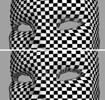
With the main areas complete, continue to work on the head, reducing any stretched areas in the texture. In particular, work on the nose area.
Inner Mouth, Eye, and Ear
Let’s stay with the head now and concentrate on the eyes, inner mouth, and ear.
1. Looking first at the eyes, apply a simple planar map here across the Z axis, scaling the UVs toward the back slightly. This will reduce the stretching along the sides. You can see the result in Figure 8.54.
2. Next, consider the geometry that makes up the inner wall of the mouth. This, too, can have a simple planar map applied to it; this time, however, as shown in Figure 8.55, project it from the X axis.
You don’t need to unwrap this area of the model, because at most it will have a basic gradient texture applied to it.
3. You can skip the teeth, which already have pretty good mapping on them. This leaves the tongue. This is another area that will not warrant much detail. This time, we will project the mapping along the Y axis (Figure 8.56). This means we can at least add some detail to her upper tongue.

4. Now you’ve come to the ear. Again, a simple planar map will work well here (Figure 8.57), but unwrap the UVs that are behind the ear.

We are almost done; there are just a few more areas to work on. Coming up next is the hair.
Hair UVs
The inner layers of the hair already have some basic mapping applied to them. This will allow us to use a single texture to map all of them.
Outer Hair
The only area needing attention here is the outer layer of hair.
1. As shown in Figure 8.58, apply planar mapping to the outer layers on both sides of the hair, projecting along the X axis.
2. With the mapping applied, select Kila’s left-side piece first and, as illustrated in Figure 8.59, adjust the UVs in the UV Texture Editor.

3. Do the same with the hair on Kila’s right, remembering to flip the UVs first (Figure 8.60).

Now comes the tricky part. We want both sides of the hair to be combined again—but if we do it now, the UVs will overlap. What we will do is separate the UVs before we combine them.
1. First of all, separate the UVs, moving them apart.
2. Combine both sides of the geometry making up the hair, welding the vertices down the center. With the left and right UVs now separated, we can work on them more easily.
We want to join the UVs across the top of her hair. Connecting them at the part will mean we can keep the flow of the hair while making sure the detail is not broken. So, we need to rotate them.
3. Select the UVs for one side of the hair and go to Polygons > Rotate UVs, opening up the options. Here you can specify what degree of rotation you wish to apply.
4. Rotate both sides until the tops are facing each other (Figure 8.61, left).
5. Use the Sew UVs tool to connect the edges down the center (Figure 8.61, right).
6. With both pieces of the hair connected now, edit the UVs a little more before moving on. Your goal is for the outer hair layer to look like that in Figure 8.62.

With the main section of the outer hair mapped, our next task is to edit the UVs on the inner side of the hair at the brow.
Inner Front Hair
To complete Kila’s hair, we will now map the polygons that make up the inside layer of her hair at the forehead.
1. As you did in the preceding section, apply planar mapping to both sides of the front area of hair across the X axis (Figure 8.63).

2. Tweak the UVs, removing any overlapping or stretching areas.
3. Separate both sets of UVs if they will overlap when the two pieces of geometry are combined.
4. Combine the meshes, welding the vertices down the center.
5. Next, you will join the two sections of UVs, using the center as the connecting point. Rather than having to manually move one set of UVs to the other, Maya will do it for you. In the UV Texture Editor, select the edges that connect, as seen in Figure 8.64, left.

6. Go to Polygons > Move and Sew UVs. What you will see is that the smaller piece has not only been welded to the larger one but has moved, too (Figure 8.64, right).
As shown in Figure 8.65, the inner pieces of the front hair are now complete.

To finish the UV work on the Kila model, we still need to work on the hands and the belt. Let’s look at the hands next.
Hand UVs
The hand is another area to which applying mapping is relatively simple.
1. Begin by applying planar mapping downward on top of the hand, adjusting it to match the orientation (Figure 8.66).
Tip
You can select both the top and bottom of the hand and apply the mapping to both areas at the same time.
2. As shown in Figure 8.67, first work on the top half’s UVs in the UV Texture Editor. Move the UVs for the sides of each finger outward, so you can add a bit of detail to them when it’s time to draw the texture.

3. Do the same for the bottom of the hand, remembering to flip the UVs first.
The finished hand should look like that in Figure 8.68.

Belt UVs
The final lower-body area to address is Kila’s belt. Initially, the mapping here was fine (because this item of clothing was created from a basic cylinder, it had inherent mapping). We have since then adjusted it slightly, adding more geometry to the back of the body, so we need to address the resulting alterations in UVs.
1. Select the belt and look at its UV layout in the UV Texture Editor (Figure 8.69).
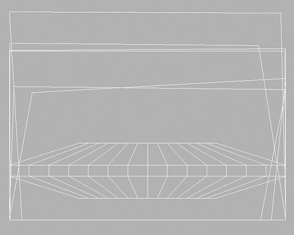
You can see the main belt area in the center—the section that looks kind of like a UFO—but there are also lots of oddly shaped boxes around it. These are from the extra polygons you created on the inside of her belt. To start with, you will move these boxes away from the main belt’s UVs, making it easier to work on them.
2. Go back to the 3D view, and select the faces you added to the inside of the belt (Figure 8.70). This will highlight them in the UV Texture Editor.

3. Now that the faces are emphasized, go back into the UV Texture Editor and go to Select > Convert Selection to UVs. Follow the illustrations in Figure 8.71. Move the selected UVs up, away from the main belt’s UV layout (Figure 8.71b).

4. The shapes of the boxes need altering, to make them cleaner and more uniform. To help with this task, make sure the grid is visible by going to View > Grid.
5. Select the UVs for each corner and, holding the X key, snap the UVs to points on the grid until they all match the same rectangular shape. You want it to look as if only one rectangle exists (Figure 8.71c).
The texture for these inner sections of the belt can be the same as part of the outside, so what you can do next is move these UVs to the same place as a section of her belt—but which section?
6. Select a face on the outside of the belt (Figure 8.72). We’ll use this section because it will have a basic texture applied to it, so no one will notice it’s the same on the inside. If we were to use the front, where the buckle will be, then that texture would be repeated on the inside, which would look wrong.

7. With the face selected, go back to the UV Texture Editor, converting the selection to UVs (Figure 8.71d).
8. Now that you know where to move them to, hold down the V key and snap the UVs for the inner belt to the selected ones on the actual belt, as shown in Figure 8.71e.
9. All that’s left to do now is edit the UVs for the top and bottom of the belt (Figure 8.73).


We now have basic UV mapping applied to the entire mesh—but before we can sign it off as complete, some adjustments are needed.
Extra Mapping Adjustments
There is one final thing to do before we can finalize Kila’s UV work. On any normal model, we could use the same mapping for the left and right arms, essentially having to draw only one arm. Kila’s arms are different, however; one has a tattoo. So we will need a separate set of mapping for each arm. The tattoo extends down onto her hand, so we will also need a separate set of mapping for them.
1. Duplicate and mirror the current arm and upper hand (Figure 8.75). Then go to Modify > Freeze Transformations; this will reset the –1 value on the Scale X attribute back to 1.

2. Although you have duplicated these pieces of geometry, the UV coordinates they hold will still be the same. To fix this, first flip and then move the UVs so they no longer overlie the ones on the left side. Flip the arm UVs vertically, and do the hand UVs horizontally.
You can see the adjusted UVs in Figures 8.76 and 8.77.


The basic UVs are mapped now. As you can see in Figure 8.78, Kila’s mapping is looking cleaner than the original. Currently, the squares of the grid are differing sizes, indicating that some areas occupy more texture space than others. This is not a problem, however; we can address this in the next section when we reposition the UVs so that they can be exported to an image file using UV Snapshot.

Exporting the UV Positions
With the help of Maya’s UV Texture Editor, we can export the UV positions as a bitmap to use as a handy guide for creating the texture. First, we need to rearrange our UVs, attempting to fit them all into a square while making sure they don’t overlap.
UV Management
When the model is finished, she will be combined into a single piece of geometry. With that in mind, let’s see how the UVs will look.
1. Select all of Kila’s geometry and take a peek in the UV Texture Editor.
As you can see in Figure 8.79, things are a bit of a mess. You can make out a few of the body parts, but there is no chance you could draw onto this image and create a successful texture map.

2. Spend some time selecting each separate piece of geometry and moving the UVs out, so you end up with everything laid out as seen in Figure 8.80. Each piece is now separate. This looks much better—you can tell what each part is.

The next problem to address is one of priority. At present the eyeball UV’s are larger than her head, meaning the eye will have much more detail in the final texture. This is clearly wrong; you need to adjust the scale of each set of UVs, enlarging areas that need greater detail.
3. To scale the UVs, simply select the piece of geometry in the 3D view. Then, in the UV Texture Editor, right-click and select UVs. Select all the UVs and press R to switch to the Scale manipulator.
While you are doing this scaling, you can begin to rearrange the UVs into their respective texture pages. Use the main grid to help you place them. Our budget is two 512x512 texture pages, so we can make use of this by dividing the UVs into three separate pages.
As a general rule, texture pages must conform to specific sizes, in powers of 2 (2, 4, 8, 16, 32, 64, 128, 256, 512, etc.). To be certain of what you are required to use, consult your manager.
4. The first page to set up will contain the main head and hands, along with the feet and belt. This will be exported as a 256x256 texture page.
5. In the next page, place all the main body parts. This will be a 512x512 page because we will need more detail in the body.
6. Place the hair on a third texture page, also 256x256 in size. Parts of this page will be transparent, so we will keep it separate.
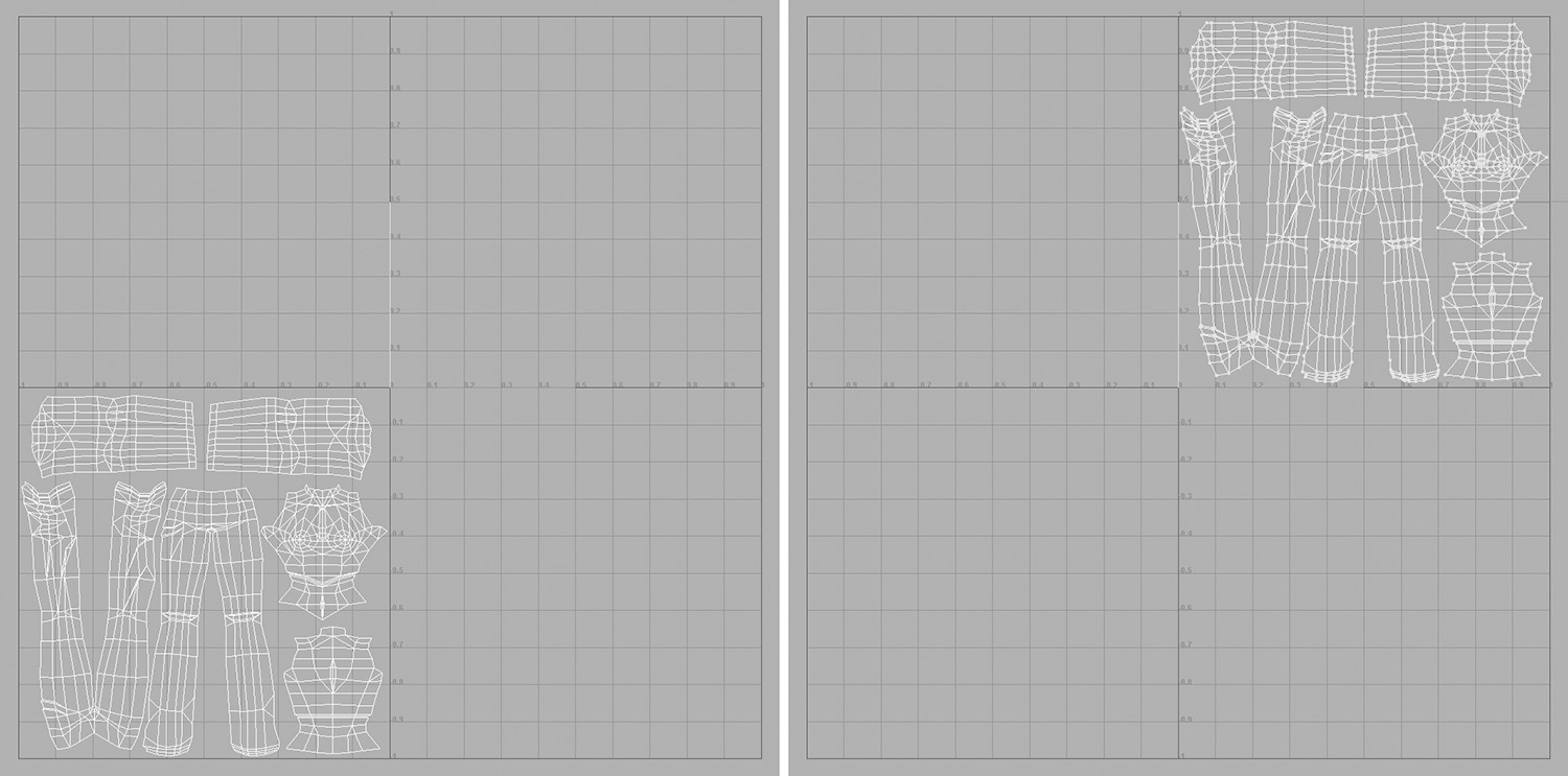
You can see the final UV layouts in Figure 8.81.

There is one final adjustment we will make before we complete the mapping process: splitting the UVs in the T-shirt.
Divide the Shirt
What we want to do now is split the UVs at the base of Kila’s crop-top. This is necessary because, with the UVs attached, some of the color from her shirt may bleed through onto her stomach.
1. Select the edges across the base of the T-shirt, as shown in Figure 8.82. Go to Polygons > Cut UVs to cut them.
2. Select the faces that make up the bottom section of the torso. Convert the selection to UVs by going to Select > Convert Selection to UVs.
3. Move the selected UVs down slightly, creating a gap.
With this final adjustment made, we have completed the process of mapping UVs onto Kila. As you can see in Figure 8.83, the squares are now much more uniform in size. All we need to do now is export the UV layout, baking it out as an image we can use as a guide when we draw her texture.

Taking a UV Snapshot
Using the UV Snapshot tool, we can export the UV layout as a bitmap, which we can then take into a digital imaging application to use as a guide for our texture.
1. Select the elements that make up the first texture page. These should be the head, eye, teeth, inner mouth, hands, tongue, shoe, eyelashes, and ear.
2. Look at Figure 8.84; these elements are already positioned correctly. To create a UV snapshot, the elements you want to capture must lie in the upper-right corner of the grid. This is the only area that Maya considers (positive 0 to 1 texture coordinate space) when saving out a UV snapshot image. Anything outside of +1u, +1v is ignored.
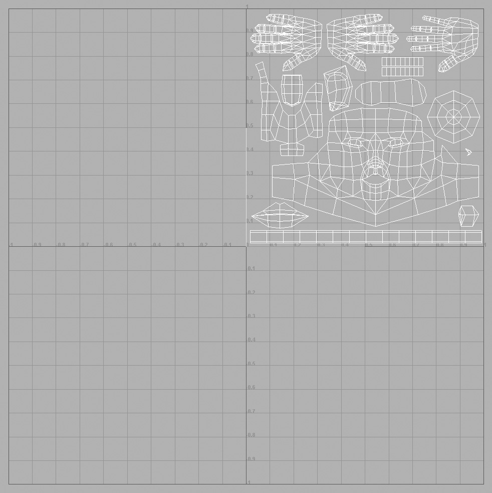
So you are ready to create the base for the first texture page.
3. In the UV Texture Editor, go to Polygons > UV Snapshot. This opens the options dialog box seen in Figure 8.85.

4. This first texture is going to be sized at 256x256, so make sure the Size X and Size Y options are set to this.
5. Click Browse, and point to where you want the texture to be stored. Call it KilaHeadUV.tga.
6. Make sure Anti-alias Lines is not enabled; this will make the UV lines exported easier to manage and follow. Click OK, and the UV image will be created.
Before we look at the snapshot, let’s create the base images for the other two texture pages.
1. Select the elements that made up the body page. This includes the legs, torso, and arms.
2. Move these UVs up to the upper-right corner of the grid (Figure 8.86); then open up the UV Snapshot options.
3. This time set the Size X and Size Y to 512.
4. Specify your place to save, naming it KilaBodyUV.tga, and click OK.
5. Finally, do the same with the hair UVs, saving these at a size of 256x256 with the name KilaHairUV.tga.
You should now have three images that you can use to guide you in creating your textures. These are shown in Figure 8.87.

The UVs have been successfully mapped and exported. What’s needed now is to piece some of Kila back together and combine her.
Recombine the Character
To begin, we need to create duplicates of the lower hand, the foot, and the eye.
1. We can mirror the hand and foot; go ahead and do this. But the eye must remain the same—simply copy this and move it across to where the right eye should be.
2. At this stage, we will only combine the main body. This will include the torso, legs, and arms. Make sure you weld the vertices afterward.
When mirroring and combining geometry, you must check the normals in particular. These are the directions in which each face is pointing. At present, she looks fine, but that is because Maya is displaying her as double-sided.
3. To check the normals, select the mesh and open up its attributes by pressing Ctrl+A.
4. Scroll down to the panel labeled Render Stats and open it up. Uncheck the checkbox labeled Double Sided.
5. Now look at your mesh; do any areas appear inside out? You can quickly fix them by going to Edit Polygons > Normals > Conform.
In most cases, all the polygons in the object will now be facing the same direction. If the problem remains, try selecting the faces and running Edit Polygons > Normals > Reverse, making sure the options are set to Reverse.
The Kila model is fully prepared now and ready to be textured. Delete the history and save the file as Kila_Mapped.mb.
Mapping Grae
Using what you have learned in this chapter, load the divided Grae model (Grae_Divided.mb), and see if you can apply UV mapping to him.
Tip
If you are having trouble mapping an area, try dividing it further into more basic shapes, such as cylinders or planes. This will simplify the task of applying basic UV mapping. Concentrate then on getting each piece looking correct before combining them all again.
Figures 8.88 and 8.89 show my finished Grae model and UV maps, which we can use in the next chapter. You can find this file on the CD as Project Files/08/Grae_Mapped.mb.


Exporting the UV maps does not mean that they are set in stone. You can edit them further if you like, as will be demonstrated in Chapter 9, “Texture Painting.” Just remember that the images you export are the UVs at that stage, so if you drastically edit them before texture painting, you may need to re-export the maps.
Summary
You now have the two models completely mapped and ready to be textured. This chapter on UV mapping has given you substantial knowledge and experience with Maya’s UV editing tools, and you’ve created a basic material.
During the next chapter, we step outside Maya and, using the UV snapshots generated here, we’ll draw the textures for our characters.