
Appendix A. Normal Mapping in Maya
A technique used in many of today’s games is normal mapping. This is a method of making a low-polygon object or character appear to have more surface detail than it actually has, by collecting intricate lighting detail from a high-polygon version and applying it to the normals of the low one. Normals are the vectors (direction) a surface is facing.
Actually an application of bump mapping, normal mapping also works from a bitmap image. Normal maps are different from bump maps, however, in terms of the information they store. Bump maps work off a grayscale image that only registers changes in height; a normal map uses an RGB image, which contains enough information to store not only height but direction as well.
Red is the direction across the object, from left to right. Green goes from top to bottom, and the amount of blue dictates the height. The stronger the color, the more that normal faces in that specific direction.
Normal maps are becoming a key part of game development, so it’s important to have some experience with creating them in Maya.
System Requirements
To generate a normal map, you have to be running Maya 6 or later. This version has all the appropriate tools that allow you to generate and apply normal maps.
There’s a plug-in available for previous versions of Maya, called RayDisplace, that will generate normal map data within Maya, but it’s a bit unstable. There are also stand-alone utilities from the major card manufacturers that process the high-polygon model data to produce the normal map data. But Maya 6 is the first in-software implementation of normal mapping.
In addition, your video card must be able to support normal maps. Maya will generate the data regardless of your graphics card’s abilities, but without the proper video card, you won’t be able to use Maya’s High Quality Interactive Render option to view the maps.
Generating a Normal Map
First you need to get Maya set up for generating normal maps.
Go to Window > Settings/Preferences > Plug-in Manager. You will see the Plug-in Manager shown in Figure A.1. This is where you control the plug-ins that are loaded into memory. Work your way down the list until you reach the plug-in called TransferSurfaceInfo.mll. Check the boxes for “loaded” and “auto load”; the plug-in will be automatically loaded the next time you boot up Maya.

With this plug-in enabled, you can use the Transfer Surface Information tool found in the Lighting/Shading menu. We will cover this shortly.
To generate a normal map, you need to create two objects:
![]() A higher-resolution mesh, from which you will extract the normal map information
A higher-resolution mesh, from which you will extract the normal map information
![]() A lower-resolution model, to which you will apply the normal map
A lower-resolution model, to which you will apply the normal map
1. Create the first of two polygon planes. Go to Create Polygon Primitives > Plane. Set both Subdivisions Along Width and Subdivisions Along Height to 20. This will give you the high-resolution mesh to work with (Figure A.2, top).

2. Call this new plane HighRes. Then move it across in the X axis and edit it, raising the vertices as shown in Figure A.2, bottom, to give it some detail. You just need something simple for this example; we are only using the geometry to demonstrate how normal maps work.
3. Create a second polygon plane, setting Subdivisions Along Width and Subdivisions Along Height to 1. This will be the low-resolution plane, to which the normal map will be applied. Call this plane LowRes.
4. Delete the history on both planes.
You now have your basic models (Figure A.3). Our aim is to get the same detail into the lower-resolution model that we have in the higher-resolution one.

Before we can generate the normal map, both sets of geometry must exist in the same place. This is so that Maya knows which object the normals will be generated from as well as what UVs to fit into on the lower-resolution mesh.
1. Select the HighRes model, and set the Translate X attribute back to 0.
2. Using the Outliner, select the HighRes model. Then, holding Shift, select the LowRes model.
3. Switch to the Rendering menu set, and go to Lighting/Shading > Transfer Surface Information. Open the options (Figure A.4).

The Transfer Surface Information tool will transfer surface information from a model to an image file. We can use it to generate our normal map.
4. Under Target Options, set Transfer to export the Tangent Space Normals. These normals are evaluated locally and can be rotated to point in the direction of the polygon.
Object Space normals always point the same direction, so they are no good for defining our map. (Make sure to consult your lead programmer on which coordinate system to use; there are some appropriate uses for object space normals.)
5. The Map Width and Map Height values define the size of the bitmap image; 256×256 is fine for this example.
6. Specify a filename and location, and the format for the image to be exported.
7. Set Shading Network to “Preserve current shading network.” You will need to edit the shader when you apply the normal map, so there is no point in creating new ones.
8. Now set the Algorithm Options:
Set Search Method to “Use outermost intersection.” This controls how each object’s intersections are handled.
Set Search Depth to 2. This specifies the farthest distance to which the algorithm will go to look for these intersections.
9. Click on Bake and Close, and the normal map will be generated.
Your resulting normal map will look like the one in Figure A.5, although it will be predominantly in blue and not grayscale.

The normal map is now exported. We can apply it to the lower-resolution model and view it interactively in Maya.
Viewing Normal Maps
We can now create a new shader that we will apply to the low-resolution polygon plane.
1. Start by moving the HighRes plane across again in the X axis, so that you can see each model separately.
2. In Hypershade, create a new Lambert material and call this NormShader. Apply it to the LowRes plane.
When you created the normal map, Maya also created a new texture file node pointing to it. You can see this in the Hypershade Textures tab and in Figure A.6. We now want to connect this to our new Lambert shader.
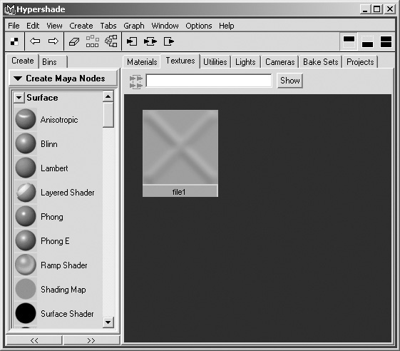
3. Open the Connection Editor (Window > General Editors > Connection Editor), and load the texture node, which should be called file1, into the Outputs section. Load the NormShader into the Inputs section.
4. As demonstrated in Figure A.7, connect the Out Color attribute of the file1 node to the Normal Camera attribute of the NormShader node.

5. Now the material is set up; all we need to do is configure the view so that we can see the normal map. Go to the view’s Shading menu and turn on High Quality Rendering, Smooth Shade All, and Hardware Texturing.

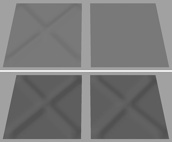
Now you will see the normal map applied to the geometry. As you can see in Figure A.9, bottom, this works quite well and gives the flat plane the illusion of detail. Next let’s see how it reacts to light.
1. In the view’s Lighting menu, activate Use Selected Lights. The geometry will go black because there are currently no lights in the scene.
2. Create a new Point Light by going to Create > Lights > Point Light.
3. Move this new light around, and you’ll notice that both objects’ surfaces react to it as if they had the same topology; yet there is a difference of 798 faces (Figure A.10).

The only drawback to normal maps (as with bump maps) is that they don’t physically alter the geometry, so when the plane is viewed from the side, as in Figure A.11, the illusion is shattered.
