
Chapter 3. Finishing and Refining
CD Files
BendingTest.ma
Kila_Basic.mb
Kila_Details.mb
Kila_Face.mb
Kila_WithFeet.mb
Kila_Finger.mb
Kila_Foot.mb
Kila_Hand.mb
Kila_WithHands.mb
Kila_Muscles.mb
MuscleLines.jpg
UpperMuscles.jpg
FaceMuscles.jpg
In Scans directory:
Hand_Top.jpg
KilaFaceFront.jpg
KilaFaceSide.jpg
KilaFront.jpg
KilaSide.jpg
You have spent valuable time developing your basic model and getting the size, shape, and proportions correct. Although it may look good and clean at this point, many areas still need work in order for this to be a successful game model. This chapter will help you take the base mesh you have created and build upon it by adding details to the geometry. In addition, you will make it deform convincingly by implementing real-life muscle structures into the topology.
Muscle Line Mapping
Let’s start working. Load the last file you saved in Chapter 2, called Kila_Basic.mb.
Look at your character model (Figure 3.1). So far, it’s quite well defined and the proportions are correct. It is a good base model. In fact, with a bit of optimization, you could use her as a low-resolution character just as she is. She would not, however, be good as our main model. We still have a few problems to address:
![]() Taken statically, she looks fine, but once you start to animate her, the flaws will show. There will be breaks or bulges in the areas that bend, either because they don’t have enough polygons or because the topology needs some work.
Taken statically, she looks fine, but once you start to animate her, the flaws will show. There will be breaks or bulges in the areas that bend, either because they don’t have enough polygons or because the topology needs some work.
![]() The mesh as it stands has too many polygons that simply are not needed.
The mesh as it stands has too many polygons that simply are not needed.
![]() She lacks physical detail in both her body and face.
She lacks physical detail in both her body and face.
![]() This model still has no hands or feet.
This model still has no hands or feet.

Our first step is to physically map the muscle groups onto the mesh. Doing this gives us a good understanding of how the mesh will move. In turn, when we animate the model, the polygons will deform, giving the illusion of muscles deforming under the skin. While we are adding these lines to the mesh, we can also add detail, giving additional shape to the geometry while we check its deformability.
Tip
A lot of detail can be gained through the texture map (more on this in Chapter 9, “Texture Painting”). Try not to get too caught up in building small details into the geometry—you’ll just use up processor power, meaning fewer polygons can be used elsewhere in the game.
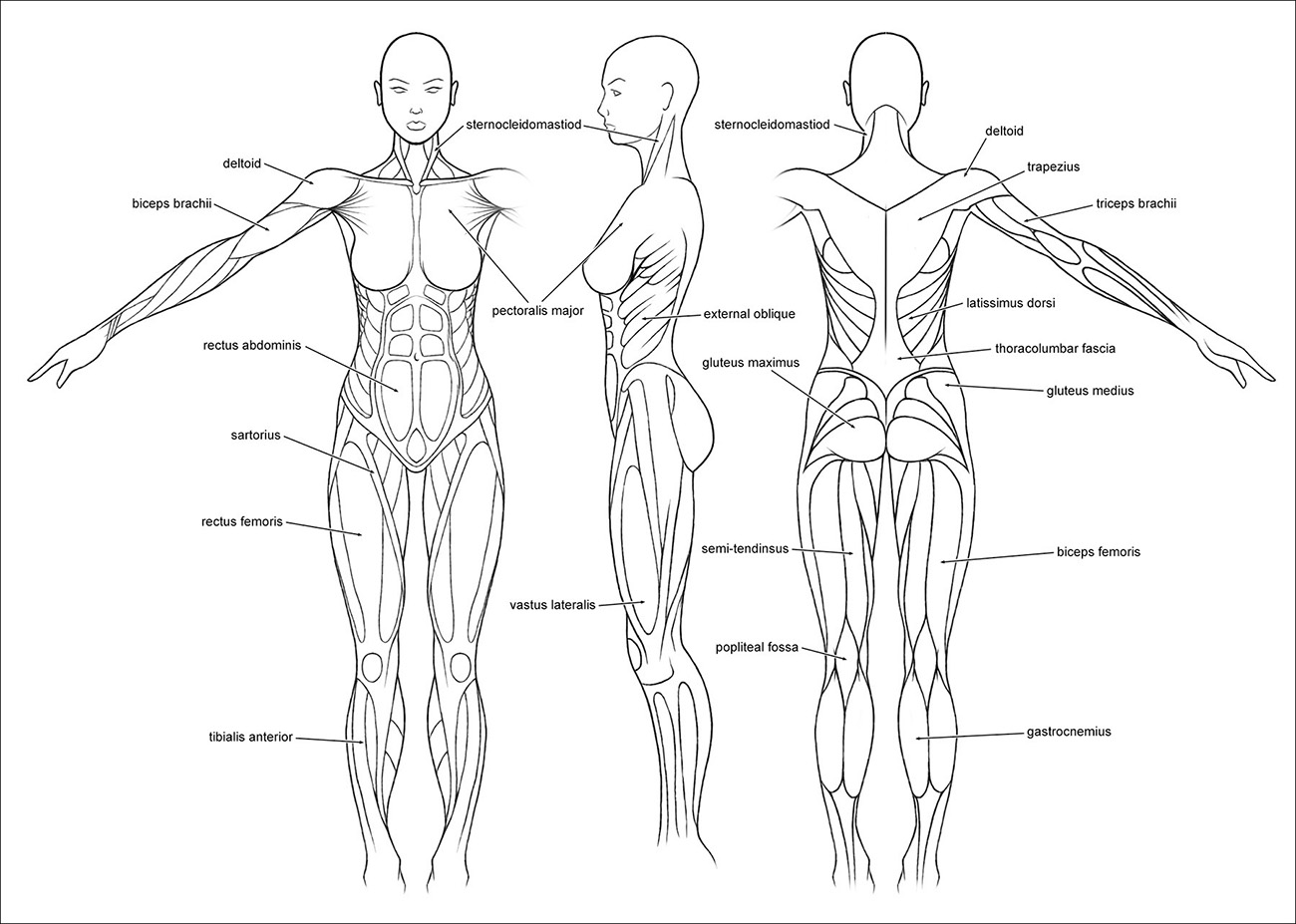
Use Figure 3.2 to guide you in placing the muscle lines on the mesh. This illustration shows a simplified version of the muscles. All we need is a basic idea to work with; at this point, we’re just implementing the main muscles.
We will start at the top and work our way down, but we will skip the head for now and concentrate on that area later in the chapter. So select the left side of the mesh, and let’s get started.
The Neck
Refer to the neck in Figure 3.2. You can see two large muscles coming from the ears and ending where the collarbones meet in the center of the chest. These are the sternocleidomastoid muscles. Let’s add these to our model.
1. We are going to split the polygons around the neck, carving these muscles into the mesh. Start by going to Edit Polygons > Split Polygon Tool.
2. As you did in the preceding chapter, click and hold on the starting edge around where the ear should be. A small icon appears, representing the starting point of the cut. Move the point up until you are at the corner where two edges meet, and release the button.
3. Select the point on the next edge where you wish to cut, and press Enter to finish that cut.
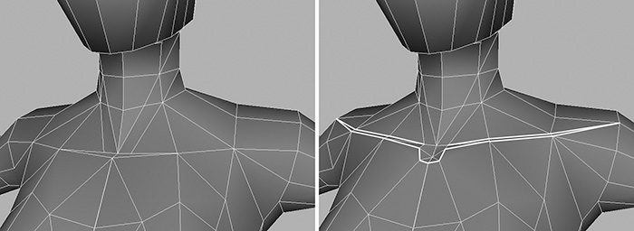
4. You need to work your way around until you get to the collarbone, as shown in Figure 3.3. You will have to do it a polygon at a time, selecting each edge that you encounter on the way.

You don’t have to always end up in the corner of two edges; you can cut anywhere along an edge. However, it’s wise to begin where a vertex already exists and try to end on one, too.
Tip
As you are cutting, you will find that occasionally you can’t go any farther with the current cut. This could be caused by an unshared edge, or faces that are flipped the wrong way. It isn’t a problem—just press G to finalize the current cut; this will also restart the Split Polygon tool. Then start a new cut from where the previous one ended.
If you are using a mirrored instance, you will notice that the cuts you make on one side will be mirrored across to the other. Also, when you create a cut, it automatically turns the new edge into a crease, making the normals hard. It’s probably a good idea to smooth them as you go along. To do this, select the edges you wish to smooth. Then go to Edit Polygons > Normals > Soften/Harden and set the options to All Soft. Click the Apply button and close the options.
I think that’s about all for the neck. As mentioned earlier, we only need a basic layout of the muscles. Adding too much detail now would be pointless because most of it will be removed later, when we optimize the geometry.
Collarbones
Moving down, we come to the upper body, so let’s implement the collarbones next (Figure 3.4, left).
Use the Split Polygon tool to carve out the details, as shown in Figure 3.4 on the right. Don’t be afraid to move some of the vertices to further sculpt the area until it resembles its anatomical reference.
If at any point you end up with tiny triangles starting to appear, as in Figure 3.5 (left), feel free to remove them. You can do this in one of two ways:
![]() Right-click the mesh and select Vertex from the marking menu, moving you into vertex editing mode. Select the two vertices on either side of the edge you want to remove, and weld them.
Right-click the mesh and select Vertex from the marking menu, moving you into vertex editing mode. Select the two vertices on either side of the edge you want to remove, and weld them.
![]() Right-click the mesh and select Edge from the marking menu, moving you into edge editing mode. Select the edge you want to remove (the middle view in Figure 3.5), and then go to Edit Polygons > Collapse. This removes the edge, bringing in the vertices on either side and welding them (Figure 3.5, right).
Right-click the mesh and select Edge from the marking menu, moving you into edge editing mode. Select the edge you want to remove (the middle view in Figure 3.5), and then go to Edit Polygons > Collapse. This removes the edge, bringing in the vertices on either side and welding them (Figure 3.5, right).

The Chest and Shoulders
Moving on, we can start working on the chest and shoulder area. Refer to the muscle reference in Figure 3.6, which focuses on the shoulder area. You can see that the huge muscle on the chest, the pectoralis major, stretches across and under the shoulder muscle, the deltoid. It would probably make sense to try and sculpt these at the same time, and then work on the armpit area before progressing to the rear of the upper body section.

Using the Split Polygon tool, create a new line following the outline of the two muscles lying across the chest and over the arm (Figure 3.7, middle).

Tip
When you’re done with an area, feel free to work on it further, adding more edges and manipulating the vertices until you are happy with the shape.
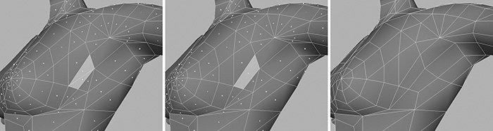
Looking at Figure 3.8 (left), the shoulder seems a little angular; this is because there are too few polygons here at the moment. When this area bends in animation, we will get quite a rough-looking deformation. You can prevent this by adding extra strips across the top as you continue adding the muscle lines.

Split the polygons as I have in Figure 3.8 (middle), following them around to the back of the shoulder (Figure 3.8, right) while continuing the line for the deltoid muscle.
Move the newly created shoulder vertices out slightly to round off the area.
The Back
This brings us nicely around to the rear of the upper body. We don’t need immense detail here, either, but it’s important to get the basic muscles in.
Starting at the top of the back and moving downward, work in the trapezius, lattimus dorsi, and thoracolumbar fascia muscles (refer again to the anatomical reference as you go). See the left and middle views of Figure 3.9.
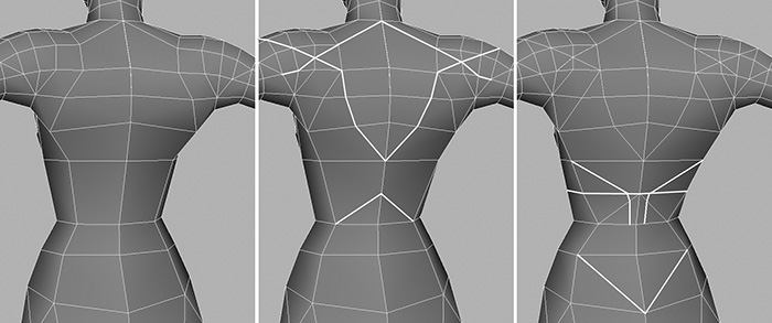
Halfway down the back, just above the hips, there is quite a large space. It will make life easier if we subdivide this area, allowing us to continue adding the back muscles (Figure 3.9, right). Follow the cut all the way around to the front of the mesh.
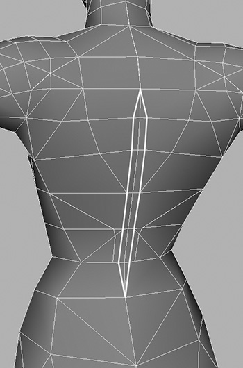
Still on her back, we could implement the spine at this point. This will be a simple recess down the center of her back. First, though, as you can see in Figure 3.10 (left), there is another large area in between her shoulder blades. Take a moment to split this area, taking the cut across the center as in Figure 3.10 (right).
Now, to create the recess for the spine (Figure 3.11), split the polygons just on either side of the center, remembering to remove any small triangles that are created. Finally, move the vertices that run down the center slightly inward.
Now is probably a good time to delete that history that has steadily been building up.
The Stomach
Moving around to Kila’s front in Figure 3.12 (left), we can begin to work in her stomach muscles. Split polygons and move vertices to get the general shape seen in Figure 3.12 (right).

It’s important to remember that when you split polygons, Maya places the cut on top of the current polygons. This means that although you have divided the polygon, it will still appear flat when viewed from an angle. In most cases, as occurred with the stomach muscles, you will need to pull these new vertices out slightly to round the area off.
The Pelvis
Moving farther down the front of the model’s body brings us to the next part to work on: the pelvic area. Because Kila is wearing jeans, there is not much point in mapping the muscles here, but we do need to make sure the area has clarity and deforms correctly.
Switch to the front view and make sure your image plane is visible. What you need to do first is mark out the top of her jeans. Judging by Figure 3.13 (left), we are in a good position. The edges at either side already lie in the correct position for the hip-hugging jeans; even the edges at the rear follow where her jeans should go, so you only need to fix the front. Go ahead and split the polygons at the front of the mesh, following the top of her jeans (Figure 3.13, right).

Now you need to address the groin area. The polyons seem to have moved down slightly so they no longer line up with the reference image. Also, the creases where the upper legs meet the hips need to be realigned. We want to end up with the mesh closely resembling the image plane, as in Figure 3.14. Don’t worry if both sides don’t match exactly; as long as one side matches the guide images, we are fine.

First move the vertices apart, creating a gap (Figure 3.15, left), and then use the Edit Polygon > Extrude Edge and Polygon > Append To Polygon tools to fill the hole. Afterward, work the vertices to round off the area, which should give you a nice, clean result like that shown on the right in Figure 3.15.

What you can start to do at this stage is include creases in your geometry. Look at Figure 3.16 (left); this is how the mesh looks now, with all the normals smooth, giving us a nice smooth surface.

Figure 3.16 (right) is the same mesh—but here there are creases added around the crotch, the upper part of the jeans, and under her chest. These creases are simple to do; it’s just a matter of making the edges hard. Here are the steps:
1. Right-click the mesh and select Edge from the marking menu.
2. Select the edges you wish to crease, in this case under her chest and around the folds in her jeans.
3. Go to Edit Polygons > Normals > Soften/Harden and open up the options.
4. Earlier, we clicked All Soft to smooth out the geometry. This time, select All Hard. Then click Apply and close the options.
This isn’t a vital part of the procedure; it just makes the geometry look better as you are working on it. To add balance to the model, as you would with a painting, you should have both hard and soft lines (edges).
The Buttocks
Time to work on Kila’s rear. At the moment it’s not much to look at (Figure 3.17, left), but we will soon fix that. As you did for the front, move the vertices to lie roughly where the creases should be, as shown in Figure 3.17 (middle).

You are now left with a huge flat area; subdivide that by splitting the polygons, as shown in Figure 3.17 (right). This still leaves the area flat, so switch to the side view and use your guide to round it off (Figure 3.18).

Rotate the model, tweaking the vertices until you are happy with the shape of the buttocks. Switch to the perspective view and look down on it from above to make sure she is nicely rounded—remember to always refer back to your anatomical reference material.
You will probably notice that from certain angles she still seems quite flat. You can fix this by subdividing the long faces at the rear by creating vertical cuts (Figure 3.19, right). Before you do this, however, delete the edges designated in the left pane of Figure 3.19. Then add a cut at either side of the crease under the buttocks (Figure 3.19, middle).

Continue tweaking, making sure you use your guide images. Figure 3.20 illustrates another area that could benefit from a little subdivision, smoothing it out and rounding it off. Here again, you’ll split the polygons horizontally to subdivide the area; in fact, you can split these all the way around, ending at the crotch (Figure 3.20, middle). When you’re done, tweak the vertices until the shape is just right (Figure 3.20, right).

Figure 3.21 shows the entire torso with all its refinements. We have added geometry not only to help the shape, but also to aid deformation.

The Arms
The torso is more or less complete now. It has more detail, and the shape is coming along nicely. The next stage is to refine the limbs, starting with the arms.
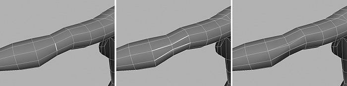
To begin, we will build in a simple elbow. I have highlighted an edge in Figure 3.22 (left); this is where our elbow will be. All we need to do is pull that edge out slightly, but first we need to create four cuts (Figure 3.22, middle). As shown in Figure 3.22 (right), this will allow us to pull out the center edge, creating the basic elbow.
Having the elbow in place helps us to complete the rest of the arm. Let’s work on the upper arm first, sculpting in the biceps and triceps. Most of the arm detail can be achieved by simply moving the vertices. And remember—we still need to refer to our muscle reference to get it right.
Begin to mark in the biceps by cutting the polygons to create the outline; Figure 3.23 (middle) shows these cuts.
Now work on molding the biceps into its correct shape. If you are at all unsure about how it should look, use a good arm reference to get it looking right. Figure 3.24 shows the finished biceps on our model.

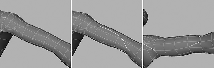
Moving around to the back of the arm (Figure 3.25, left), we can work in the triceps. First cut in the outline shown in Figure 3.25 (right), and then move the vertices to achieve the desired shape.

You may not need to cut any polygons for the forearm; just make sure the shape is correct. The muscles run down toward the wrist, as our edges do anyway, so it would be a waste of time to work in every muscle; further detail in this area can be gained by her texture.
We now have enough definition in the upper body. You can, if you like, spend a bit more time mapping in the rest of the muscles, as I have in Figure 3.26. Round off this section by doing what makes up 90 percent of most modeling: rotating and tweaking. Move around the model and make sure it is smooth, anatomically correct, and clean.

When you’re done, delete the history and save your work as Kila_Muscles.mb.
Legs
Depending on the character you are creating, you may need to add muscle lines to the legs. Figure 3.27 shows a different character I created a while ago; she has muscles mapped on her entire body. This was done by following an appropriate muscle reference and splitting the polygons to outline the muscles.

Face and Upper Body Detail
Kila’s torso and limbs are sculpted now to a point where we can move on to another area. We will begin by adding more details to the geometry, starting as before from the top and working our way down.
The Face
It’s about time we gave Kila a face. We will begin working on her from the side, so switch to the side panel now and focus in on her face.
The image in Figure 3.28 (left) will do for the head, but it is of very low quality. This is where our head model sheet from Chapter 1 comes in handy. Scan in the sheet and divide it up into two sections, as you we did with the body model sheet.

Import the side image into the side panel (or load in the file 02/Scans/KilaFaceSide.tga from the CD), and position and resize it until it is the same scale as the current head (as seen in Figure 3.28, middle).
You now have a better image to work with. Take a look: The first thing that stands out is that the head is tilted slightly. So we must select the vertices of the head and rotate it, so that it fits the head in the image plane (Figure 3.28, right).
In order to add more detail to the head, we must add some more vertices and polygons to the face. We could split the polygons where we need them, but since we need to divide a large area, we can do something quicker.
1. Referring to Figure 3.29 (left), select the faces at the front of the head.

2. Go to Edit Polygons > Subdivide and open the options.
3. Set Subdivision Levels to 1 and Mode to quads.
4. Click the Apply button to finish, and close the options.
As illustrated in Figure 3.29 (right), Kila’s face is now divided up into smaller sections, allowing us to begin refining the area.
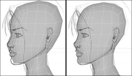
Switch to the side view (Figure 3.30, left), and begin to manipulate the vertices to better fit the image in the image plane (Figure 3.30, right). When you’re happy with the side view, switch to perspective view and begin to work on the rest of the vertices. At this stage, you’re not aiming for any details such as eyes, nose, or mouth. For now, work on achieving a smooth area and getting the overall shape of the head. See the progression in Figure 3.31.

Depending on the accuracy of the head images, you may find it difficult to get the mesh looking exactly like the front and side images at once. Don’t worry; try to find a happy medium. What’s important is that it looks like the character when it’s finished. The topology is your concern at this stage, especially if the character will have any lip-sync capabilities, as most characters do.
Nose
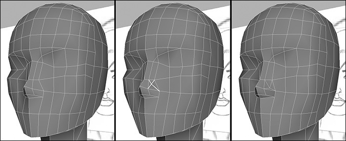
The basic head shape is in place. Its time to work in some features; let’s begin with the nose. As shown in Figure 3.32, switch to the front view and split the polygons as demonstrated. These should follow the line of the nose, then the eyebrow.

Switch to the side view and move the vertices to match the nose (Figure 3.33). Switch to the perspective panel to see how things are looking, making any needed adjustments to retain the shape.

Still in the perspective view, cut the polygons as shown in Figure 3.34 (middle), making an X. Move the new vertex that’s in the center of the X, pulling it down slightly to give her nostril more definition (Figure 3.34, right).
Lips and Mouth
Let’s continue and create a rough version of her lips. Move to the front view and split the polygons around the outline of the mouth (Figure 3.35). You will see that the nose needs to be thinned out slightly to match the image, so we may as well implement this while we are here.

Switch to the side view and move the vertices to match the lips in the image (Figure 3.36, middle). We could leave the lips as they are, but they look a little flat and we need to give them some volume. To do this, simply divide them down the center. Then, as shown in Figure 3.36 (right), pull the new vertices outward to round off the lips.

At this stage, we can begin to implement the muscles lines of the face (as seen in Figure 3.37). We are currently working on the mouth area, so let’s split more polygons around the mouth to map out the muscles. This will also help us add more definition to the chin and the rest of this facial area.

Following the reference in Figure 3.37, create a ring around the mouth (Figure 3.38). As in Figure 3.39, switch to the side panel and fill out the chin.


Now open up the perspective view and work on the area until the shape looks correct. Figure 3.40 shows the mouth area completed with the first set of muscle maps.

Eye Area
Let’s now work on the eyes. Go to the front view and, as illustrated in Figure 3.41 (right), split the polygons, creating the outline for her eye. The polygons in the center of the eye won’t be needed, so select the faces inside the eye’s outline and delete them.

With the outline for the eye in place, move the vertices of this outline to fit the shape of the eyeball. You’ll need an eyeball first in order to do this, so create a basic sphere and position it where the eyeball would be (Figure 3.42).

Using this placeholder eyeball as a guide, move the vertices of the eye so that they follow the curve of the eyeball (Figure 3.43). Make sure to leave a small gap between each vertex and the eyeball.

With our basic facial features in place, we can start to refine them by adding more detail. Staying with the eye, carve in a ring around it (Figure 3.44, left). This subdivides the polygons, allowing you to smooth out the area; it also act as a muscle line. Shape these new vertices to fill out the area around the eye. Then you can build in the eyelids (Figure 3.44, middle). These will be quite important to the face’s animation; the eyes must be able to open and close.

To fill in the gap between the eyelids and the eyeball, simply select the edges shown in Figure 3.45a and extrude them inward (Figure 3.45b).

Kila has very long eyelashes. To achieve this look, all you need to do is repeat the extrusion task you just did for the eyelids. Select the edges on the rim of the eye, but this time extrude them outward, as seen in Figure 3.45c. Manipulate the vertices to match the shape in the front guide image, splitting the outer edges highlighted in Figure 3.45d, to separate the upper and lower lashes. Figure 3.45e shows that Kila’s eyes are essentially complete.
With the basic features in place, let’s continue to refine the face. Before you continue, delete the history on the geometry and save the file.
Face Refinement
We will begin by working on the nose. Looking in from the side, as in Figure 3.46 (left), you can see that the nose is quite sharp and angular. Split some of the polygons, and move the vertices to smooth out the nose (Figure 3.46, right).

Moving to the front view, edit the vertices to smooth out the nose even more, adding cuts to the underside of the nose (Figure 3.47, right).

Now switch to perspective view to see how you’re doing. It’s coming along well—but if you look upward from the bottom, her nose is still quite sharp and pointed. In Figure 3.48, I have split the polygons vertically across the nostril, allowing the nose to be rounded off.
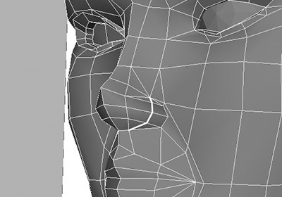
To complete the nose, insert a hole underneath to create the nostril. Split the polygons underneath, creating an X (Figure 3.49, middle). Move the new vertex up into the nose to create the nostril cavity.

As you’ve done with everything else up to now, have a final look around the nose, manipulating the vertices to fill out the shape. You should end up with the nostril as illustrated in Figure 3.49 (right).
Nose and eyes are done; moving on brings us to the mouth. Switch to the side view and start working the vertices to refine the shape of the lips. Split the polygons to round off the lower lip. Look at the model in the perspective view now, and divide the lips as illustrated in Figure 3.50 (middle). Next, it is merely a case of sculpting the area until the lips better fit your reference imagery (Figure 3.50, right).

Before we can leave the head and move on, we must fill out the chin. In Figure 3.51 (left), the area under the chin is very flat and the chin itself is quite angular. To rectify this, start by splitting more polygons, following the ones on the side of the head down to the bottom (Figure 3.51, middle). Then adjust the vertices to fit the outline in the image plane (Figure 3.51, right).

The final stage for the head is to spend time making sure the shape is perfect. We have all the features in, and now we must make sure they resemble the character we are building.
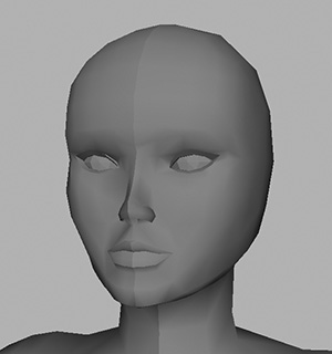
Getting the face right is crucial, so load in the original color image that was created in Chapter 1 (Figure 3.52). This is how the character should look and will be our reference for this part of the model.
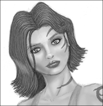
Put as much time as possible into refining the face and head. Get it just right (Figure 3.53) before you go forward. Then delete the history and save your work as Kila_Face.mb.
The Neck
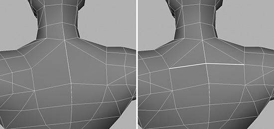
Progressing down from the face, we come to the neck. There’s not much you can really do here except perhaps to make the muscle you defined earlier, the sternocleidomastoid, a little more pronounced (Figure 3.54).

You can achieve this simply by creating a split all the way down the center of the muscle (Figure 3.54, middle). Then manipulate the vertices until you have the required shape (Figure 3.54, right), giving the muscle slightly more definition.
Continuing on, the shoulder area seems fine for now. We may need to add some more subdivisions to get a nice round shoulder when she lowers her arm, but we can test this out when we come to the deformation tests (Chapter 6, “Deformation Testing”).
The Armpit
Next comes the armpit. It is important for this part of the anatomy to be correct in order to achieve good deformation. It’s wise to refer to a real armpit, so look around for a good photo to use as a guide (or use a mirror). Visit one of the links suggested in Appendix B; they will have many reference images.
To start, split up some of the larger areas as seen in Figure 3.55 (middle), giving you more pieces to work with. Using your reference as an example, move the vertices around until you have a better shape (Figure 3.55, right).

I like to keep my models clean and tidy, so I prefer to work in quads. (A quad is simply two triangular polygons combined to make a square.) This method has a second advantage: If you are creating a subdivision surface model, using mostly quads will result in a smoother model when it’s converted (see “Subdivision Surfaces” in Chapter 2).
To create a quad, select two adjoining triangular faces (Figure 3.56) and go to Polygons > Quadrangulate to convert them to a single quad. This technique is particularly useful if applied to a number of faces at once. Another way to create a single quad is to select the dividing edge and delete it.
Continue checking the model for areas to improve. Notice the polygon just under her chest (Figure 3.57, left), which is at a sharp angle to the polygon below, making this area look angular when you rotate around the model. It is best that we remove this polygon, rebuilding the area to smooth it out.

The quickest way to accomplish this is to split the faces as shown in Figure 3.57, middle. Select the new vertices and snap each one to the topmost vertex of the cut. Finally, weld them together, resulting in the simplified but smoother area seen in Figure 3.57, right.
The Navel
We’ve accomplished a lot—except for the hands and feet, there really aren’t many more details we can add to Kila’s main body. (In Chapter 4, “Modeling Details,” we’ll get to add clothing and other areas like ears and hair.) So let’s just finish this section by giving her a navel.
For a general game model, the navel could be achieved with the texture, causing no major problems. But for demonstration purposes, I will go ahead and create it using the cutting and shaping method used throughout this chapter.
1. Switch to the front view, making sure the image planes are visible. Zoom in, as in Figure 3.58 (left), to where the navel would be.

2. Make two small cuts, resulting in a diamond shape (Figure 3.58, right). The cuts need not follow the image perfectly; they just need to be in the correct place.
3. Select the faces just created (Figure 3.59, left). Then select Edit Polygons > Extrude Face, and move them inward slightly.

4. As you can see in Figure 3.59 (middle), some faces have been created down the center of the navel. Delete these before moving on to manipulate the inside of the navel, shaping it correctly (Figure 3.59, right).
Kila’s navel is fairly basic for now; this is because we are not sure how it will look in the game, or even if it will ever be seen up close. After the model is complete, we can come back to the navel and add details or remove it if necessary.
At this point, Kila’s essentials have been modeled. She now has a face, and the primary areas of her body have been shaped and adjusted to give her an explicit form. If we require it, more-precise muscle definition can be achieved with the texture, as can many of the smaller details. For now, her shape looks good and will deform well.
Delete the history on your geometry and save your work as Kila_Details.mb.
Hands
Hands in a game environment can come in many shapes and sizes. During our research in Chapter 1, we discovered that Kila is to have a fully working hand, meaning all the fingers can be animated separately. If you are at all unsure about the number of fingers your character should have, talk it through with your lead artist.
Although we already have determined the hands we need for Kila, I will illustrate in this section how to develop various resolutions for a hand, covering any eventuality. The best starting point for this task is to build the higher-resolution version and then work down.
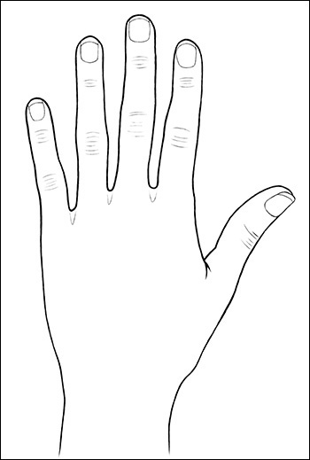
If you already have a selection of hands at your disposal, as I do in my Morgue, you can simply import one that’s appropriate, attach it, and keep working. But let’s say you’re starting from scratch. You’ll need some sample hand images that you can import into Maya and use as a guide. The image in Figure 3.61 is the one we will use as a base in this discussion.

Building a Finger
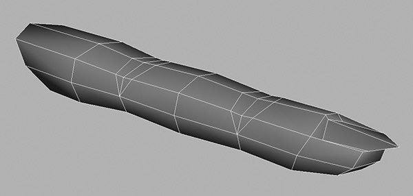
Before we continue, let’s look briefly at how the finger is going to bend, and the best way to build this. Load the file called BendingTest.ma (located on the CD in the 03 directory). It comprises five primitive fingers, as seen in Figure 3.62 (top). If you move along the timeline, the fingers will bend (Figure 3.62, bottom).

Notice that the finger on the far left is pinching badly as it bends, while the one on the far right keeps its shape. This is an example of how adding a few polygons in the correct place can help. It may very well be, however, that in your game the character’s fingers are never seen up close, so the far-left finger will do just fine. So let’s begin with building a simple finger. Once we have one finger complete, we can duplicate it and use it for the rest of the hand:
1. Start with a new scene and go to Create > Polygon Primitives > Cube. Create a cube with a Width of 6, Subdivisions Along Width of 3, Subdivisions Along Height of 2, and Subdivisions Along Depth of 2 (Figure 3.63).

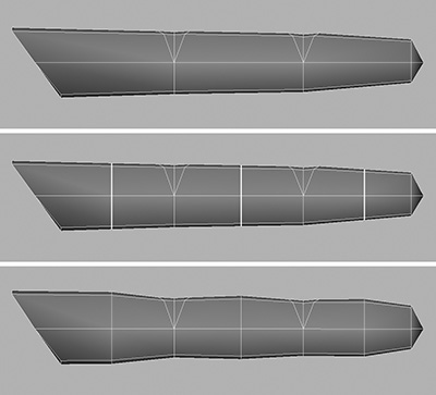
2. Use the Split Polygon tool to follow the cuts shown in Figure 3.64 in the middle. This defines the knuckle areas.

3. With the knuckles in place, start to shape the rest of the finger. Move the knuckles down the finger until they are correctly positioned. Then, as in Figure 3.64 at the bottom, taper the whole finger down toward the tip.
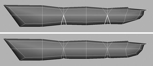
4. Looking from the side view (Figure 3.65), our finger is a little flat. We need to give it more shape. Subdivide the finger further, but this time don’t use the Split Polygon tool. Instead, go to Edit Polygons > Cut Faces Tool.
Like the Split Polygon tool, Cut Faces cuts the faces for you, but in this case you define a single straight line that determines the axis of the slice. Maya then slices through the entire mesh, following this line. A word of warning: Be careful when applying this tool; it will cut through both sides of the mesh.
Try it here: Select an area between the top of the finger and the next knuckle, holding down the mouse button. A line appears, spanning the entire view panel. Move the mouse, and the orientation of the line alters, to determine the line that will be sliced across the finger.
Make sure the line is completely vertical, and then let go of the mouse button. A line has been cut all the way through the mesh, saving you the effort of having to create each cut individually.
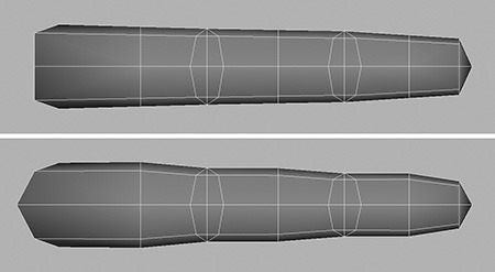
5. Continue to work, making a total of three slices, until the finger looks like that in Figure 3.65 (middle).
6. Now that you have these extra divisions, you can add definition to the finger. Look at your own finger from the side and try to match it (Figure 3.65, bottom).
7. Switch to the top view and continue shaping, as illustrated in Figure 3.66.
8. Moving on, create the fingernail. Using the Split Polygon tool, create a cut at the end of the finger to outline the actual fingernail (Figure 3.67, middle). Manipulate the vertices until you achieve the required shape (Figure 3.67, right).

9. While you’re at the fingernail end, you can remove a couple of unneeded vertices. You should wind up with two vertices on either side of the nail, as shown in Figure 3.68 (left). Select these and weld them to the vertices above them (Figure 3.68, right).

10. Finally, using reference or your own finger, continue working on the overall shape until you are happy with the results (Figure 3.69).
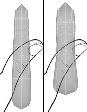
11. Referring back to our bending test in Figure 3.62, we can see that the finger we’ve just designed will more than likely pinch underneath as it’s deforming. Let’s try to fix that. As illustrated in Figure 3.70, split the polygons until you get two upside-down V shapes, almost mirroring the knuckles above.
12. For the last time (on this finger, anyway), work on the general shape until you are satisfied.
What we have now is a decent finger model—although it may have a bit too much detail or too many polygons for the actual character you are building. Figure 3.71 shows how the finger we have just built can be reduced to a lower iteration in a matter of minutes. All I did to achieve this was to snap the vertices I didn’t want to the ones I wanted to keep, and then weld the whole finger using a low distance of 0.1 or 0.01.

Before continuing, delete the history on your finger and save as Kila_Finger.mb.
Creating All the Fingers
As we progress with building the hand, I will demonstrate the lower-resolution version next, for comparison. The technique is the same, no matter which finger you use.
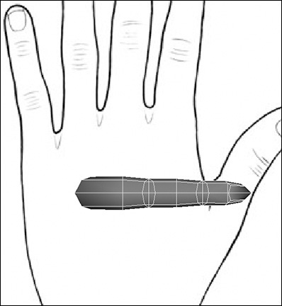
1. Now it is time to use our guide image, the one in Figure 3.61. Switch to the top view and import the image as an image plane. Go to View > Image Plane > Import Image and select the image called Hand_Top.jpg (on the CD in the directory 03/Scans).
2. Size at the moment is not really an issue, as long as the proportions are correct. So instead of altering the image plane, simply rotate and scale the finger until it matches the middle finger in the image, lining it up with the knuckle as in Figure 3.73. Keep the rotations to 90 degrees for now.

3. Before creating the other fingers, check that the proportions are correct. As in Figure 3.74 (left), move the finger to the right of the image’s middle finger and compare the proportions. The size looks fine, so go ahead and compare the knuckles’ positions. Make any necessary adjustments (Figure 3.74, right) before proceeding.

Note
It’s important to get the finger right, because any changes you make later will involve altering five fingers instead of one.
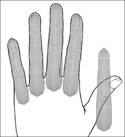
4. Once you are happy with the finger’s proportions, duplicate it four times. Then position and scale each copy to fit its corresponding finger in the image (Figure 3.75). Don’t do the thumb yet, however (you will need to edit the thumb a bit more before positioning it).
5. Now we’ll look at the thumb. It’s shaped differently from the fingers, and it’s set on an angle. So before positioning it, we want to reshape it. Waiting to do this later would make the task more difficult. You can achieve the desired shape by simply selecting areas of vertices and scaling them up until the digit looks thicker, resembling a thumb (Figures 3.76 and 3.77).

6. To finish the thumb, reposition it so it lies over the thumb in the guide image (Figure 3.78, left). Then rotate it around its X axis by 45 degrees (Figure 3.78, right).

7. The fingers are ready; you may want to move the fingers up slightly as I have done in Figure 3.79, so they lie above the thumb.

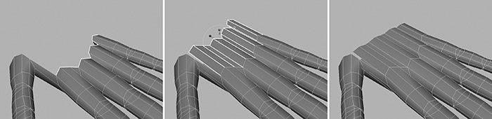
8. Moving on, combine all the digits so they are a single mesh. As you can see in Figure 3.80 (top), we still have the ends of the fingers capped. Before we start work on the palm, remove these caps (Figure 3.80, bottom).

The Hand
Now we can start on the main part of the hand. Use the Append To Polygon tool to bridge the gaps between the fingers and between the forefinger and thumb (Figure 3.81), filling in the outer areas.

Next, bring the fingers up to meet the thumb by selecting the edges (Figure 3.82, left) all around the outer ring of the fingers. Select them all the way underneath, too. Use the Extrude Edge tool to pull the edges out to meet the thumb (Figure 3.82, right). Finish by flattening the new edges. You can use the Scale manipulator, or the small square on the Extrude Edge manipulator to do this.
If you are experiencing problems aligning the edges of the fingers you can align the edges manually by using the standard Move manipulator and snapping the edges to the grid. First, open up the Move tool options and deselect Retain Component Spacing. With this setting turned off, when we use the grid snap tool to align the edges they will all keep their original spacing relative to one another. Select the edges and, holding X, move them along the Z axis. All the edges will align themselves along a straight line perpendicular to that axis. Release X, and position the edges correctly.
Now it’s time to work those vertices. Shape the existing palm and upper hand areas using the guide image and any reference material you have (Figure 3.83).

You now need to do another extrude. You should have a complete loop at the inner side of the hand (Figure 3.84, left). Select the edges around this loop and extrude them (Figure 3.84, middle). For this extrusion, pull it right down to the wrist and scale it inward, across the X axis (Figure 3.84, right). Look in the Channel Box; you will have all the attributes for the extrusion available. Set Divisions to 2.
More work on the vertices is needed now, shaping the palm, upper hand, and upper wrist areas until the entire hand is correct. Start by rounding off the wrist area and working your way up. We appear to have quite a few polygons in the palm area, and it would be easier to edit if we removed some of the unnecessary ones. Select the edges shown in Figure 3.85 (left); they should lie between the tendons on the back of the hand. Select the same edges on the underside, too, and then go to Edit Polygons > Collapse to remove them (Figure 3.85, right).

FIGURE 3.85 Collapse some of the edges making up the hand, cleaning up the area and making it easier to edit.
Kila’s arms were made up of 10 subdivisions around the axis, so the wrist area of the hand should match this. As shown in Figure 3.86 on the left, select every other edge and collapse them. This leaves 12 remaining (Figure 3.86, right), but we can remove two more later after we have worked some more on the area.

Now we have a simpler mesh to work with more easily. Continue shaping the palm and upper hand; use the tendons on the back of the hand as a guide, lining up the edges to follow them.
Looking at the hand on the left in Figure 3.87, we could use some more vertices across the middle to fill it out. As you did earlier, use the Cut Faces tool to cut a line all the way through the hand (Figure 3.87, right). Then shape the upper part of the hand until you are happy with it (Figure 3.88).
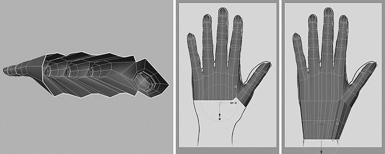
Next, rotate the hand so you are looking at the palm (Figure 3.89, left). Our next job is to create the muscle that lies at the base of the thumb. Following Figure 3.89 (right), split the polygons outlining the muscle, adding a second line across the center that will let you define the muscle.

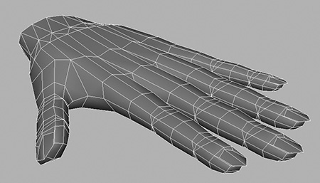
The final addition to our hand will be the knuckles. To add these, you’ll add an X above each finger (Figure 3.90, right). Do this as you’ve done before, by splitting the polygons. Then pull upward the vertices that are now in the center. This will make the knuckles more pronounced.

And there you have it—a hand for Kila. Admittedly, it probably has more polygons than it needs, but we can remove these when we come to the optimization process in Chapter 5, “Model Optimization.”
Hand Resolutions
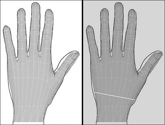
As mentioned earlier, I followed the same procedure for the other hand, but using the lower-resolution finger. Figure 3.91 shows both hands.
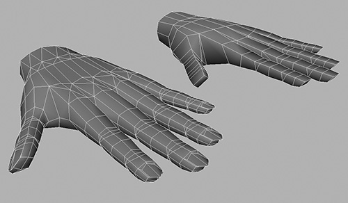
The hands may look quite different up close, especially with the wireframe visible. But look at them in Figure 3.92, at a distance similar to how they will be viewed in a game. From afar, you can hardly tell the difference. This is the key to creating anything for games: If you can’t see it in the game, don’t waste time creating it.

FIGURE 3.92 Although there is a difference of 604 polygons between these two hands, you can’t tell when they’re viewed in the game.
One hand has 1010 polygons, but the other has only 406. Using the second, lower-resolution version could save you 604 polygons, freeing up precious processor power. And this isn’t the lowest we can go; we can reduce the number of polygons even further.
Look at Figure 3.93; these are some of the hands in my Morgue. You can see how they differ. You could remove some of the fingers if they will not be needed, merging them so they are no longer individual; or you could merge them all, leaving a mitten-type hand.

Many games use finger merging not only to cut down on the polygon count, but also the joint count. You see the mitten hand on all the main characters of the ever-popular Grand Theft Auto series on PS2. In that type of game, you need all the processing power you can squeeze out of the system in order to run everything that is happening in the background. Using the mitten-type hand can also mean you use 4 joints to animate it, rather than the 15 needed to move a fully rigged hand, again saving processing power.
Other games move the detail up a notch and just combine the pinkie, ring, and middle fingers, leaving the index finger and thumb free. This type of hand is useful for characters that need to hold weapons, or that may briefly be seen up close. The separate index finger gives the illusion of a fully working hand.
If you’re on a tight budget and the hand does not need to be animated, you can always create a hand in a dynamic pose. This means you only need the wrist joint to animate it and, depending on the game engine you’re using, you can swap the hand models when you need a different pose.
It is important to try and use the lowest version possible for a hand. This is an area that can eat up lots of power, so if you don’t need a fully working hand, don’t use one. You can easily create a low-resolution version from the high version that we built in this chapter. Simply select vertices you want to remove and, holding down the V key, snap them to the vertex that you want to keep. Just remember you will need to weld them, or the polygons will still exist.
Attaching the Hand to the Model
All that is left to do now for Kila’s hands is to attach them to the model. We will use the higher version for this discussion. If we have enough polygons in our budget, it will be nice to keep some of the detail, since she is the main character and we may wind up seeing her hands up close.
1. Delete the history, and save your current file as Kila_Hand.mb. Then load the last active file containing the body, which was Kila_Details.mb.
2. Import the hand into Kila_Details.mb, by going to File > Import and opening Kila_Hand.mb.
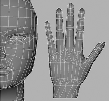
3. No doubt the hand in your file is absolutely massive, so scale it down. As a guide, the hand should be about the same size as the span from chin to forehead on the face (Figure 3.94).
4. Position the hand at the end of the wrist, overlapping the first strip of polygons with the palm down, as shown in Figure 3.95.

5. Delete the first strip of polygons from the hand (Figure 3.96, left), and then combine both meshes so that you can stitch them together. If you had a mirrored instance for the arm geometry, it will have been removed and you will need to re-create it.
6. Match up vertices that lie closest to one another and weld them (Figure 3.97), as you did when you stitched the limbs to the torso. Because you have 10 subdivisions on the arm and 12 on the hand, there will be an area where you have to weld three vertices together. Start at the top and then move to the bottom, working on the sides last.

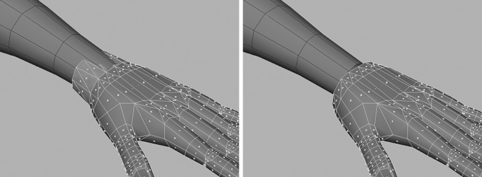
7. Because you began with differing numbers of vertices, you will end up with an area that looks “wrong”—maybe it’s just not as smooth as it should be. Since you welded the side vertices last, this is where the problem area lies. There are quite a few polygons on the hand, so you can afford to lose a few from here. Select the edges highlighted in Figure 3.98, and collapse them.

Work some more on the problem area until you are satisfied with the shape (Figure 3.99).

When you’re done, delete the history and save your work as Kila_WithHands.mb.
Feet
Kila is wearing shoes, and most of the time her shoes will be simple shapes. For the purposes of this discussion, however, we will explore the possibilities of bare feet.
I have in my Morgue various versions of feet, just as I do hands. Figure 3.100 shows some of these choices, which are quite basic. As you look from the left to the right, you can see how I have duplicated and reduced the higher-resolution foot to create the next in the line. So they start at 140 polygons and end with just 25.

In this section, we will see how to create the higher-resolution foot. Then, if we need to, we can reduce it. Once we have our bare foot created, a few simple steps will transform it into Kila’s athletic shoe. Let’s start with a new scene.
1. There are 10 subdivisions around the axis of our leg, so let’s keep that amount for the foot. Create a new cylinder with Subdivisions Around Axis set to 10 and Subdivisions Along Height at 3.
2. Switch to the side view. As demonstrated in Figure 3.101, select the faces at the front and extrude them, setting the number of Divisions to 4.
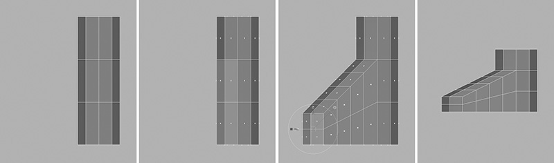
3. Scale the extrusion down the Y axis and move it down to line up with the base of the cylinder. The basic foot shape may be a little high, as it is on the far right in Figure 3.101, so scale the entire mesh down slightly.
4. Still in the side view, start to adjust the vertices as shown in Figure 3.102, to get a better-defined foot shape.

5. Switch to the perspective view and make the same adjustments. Try to sculpt the mesh, transforming the shape until it resembles a foot (Figure 3.103).

The general shape of the mesh now represents a foot, time for a quick tidy-up:
1. First remove the faces from the top of the foot, the top cap of the original cylinder.
2. Next, look at the bottom of the foot (Figure 3.104). It’s a bit of a mess, so spend some time cleaning it up a little. Snap the vertices on the inner sole to the outer ring and weld them, until the sole resembles the one on the right in Figure 3.104.

3. A key part of the foot is the ankle, and we will add this next. Following Figure 3.105, split the faces, carving in a general outline for the ankle. Do this on both sides of the foot.
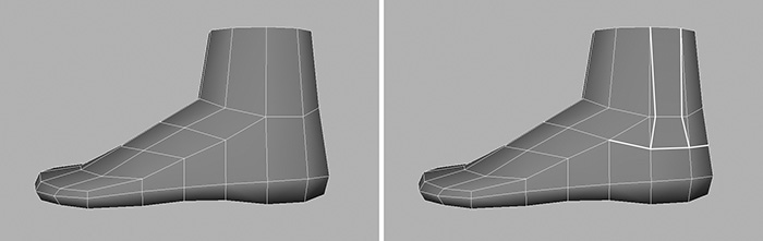
4. Finally, pull the ankles out slightly so they are more pronounced (Figure 3.106). Remember that the outer ankle joint is lower than the inner one.
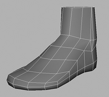
Hopefully, the material in this section will have given you a base to build upon. For our purposes, we just need to alter this version of the foot slightly until it looks more like Kila’s shoe; you can see the result in Figure 3.107.

Delete the history on the foot and save it as Kila_Foot.mb.
You can go on from here, as you wish, to add more details to the foot—individual toes, for instance. Simply divide the front of the foot into five segments, separating them to create the toes.
Attaching the Foot to the Model
Load the file created earlier, Kila_WithHands.mb. We will now import the foot into this scene. As you did with the hand, scale and manipulate the foot until it is in the correct position (Figure 3.108, left).
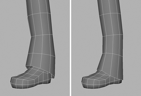
Before saving this file and ending this chapter, alter the bottom of Kila’s trousers to fit the new foot (Figure 3.108, right). Then, as always, delete the history, and save the scene—this time as Kila_WithFeet.mb.
Now when you mirror the geometry Kila will have both feet.
Summary
Kila now has the main details she needs (Figure 3.109). This chapter showed you how to add detail to her face, arms, main body, and legs. We also generated a full hand and experimented with making a foot.

Next, we will add details to her in the form of hair, clothing, and more.