A mathematician is a device for turning coffee into theorems. | ||
| --Paul Erdos | ||
When working with standard applications, users are accustomed to clicking on a control or widget and having some degree of interaction with the control. Take a push button, for example; users click on a push button and a visual cue is used that presents the button in a depressed state, and the button launches an on-click event that performs some action. Users are also accustomed to this same level of interaction with 3D applications.
Many 3D applications have dialogs that can modify and manage data without the need to interact with the scene, but visual interaction is much easier and faster to perform than clicking through dialog after dialog. For example, 3D applications typically allow the user to reposition objects within a scene by using the mouse and by typing in coordinates in a dialog box. It does not take a lot of thought to figure out which method is faster and more productive. If using the mouse is easier and more productive, why bother with field-driven dialog boxes at all? Using the mouse is quick, but typing coordinates into a dialog is much more precise than using the mouse and trying to coerce an object into a specific location.
In order to handle mouse-clicking, the application must be able to read mouse click events, extract the coordinate (X, Y), and perform an intersection test against a particular control to see if it was activated. Thankfully, this process is automatically handled by Win32 user interface controls, but we are not so lucky in the 3D world.
This chapter will cover the math and implementation behind converting coordinates in screen space to world space and performing intersection tests, otherwise known as picking.
Performing intersecting tests against Win32 controls is very simple, since the mouse coordinates and the control bounds are both in screen space (X, Y). Intersection tests from screen space coordinates to world space bounds (X, Y, Z) require a bit of math since we do not know the relationship between the 3D object and its projection. It is also important to state that we are using a left-handed coordinate system, which is the default for Direct3D. OpenGL uses a right-handed coordinate system, so the math and code will have to be adapted to get it working. Take a look at the source code for the gluUnproject function of OpenGL if you are unsure of how to do this.
Figure 27.1 shows the relationship between the origin of projection (screen space) and the projection window (world space).
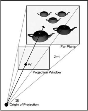
Figure 27.1 shows that the teapot was projected to the area surrounding W on the projection window, corresponding to screen point S. With that said, we can compute a picking ray that will project from the origin and pass through W. Intersection tests can then be performed against all objects in the scene to determine which objects were picked by the user. It is possible that the intersection tests performed on the scene objects will return no hits. This simply means that the user did not click on any objects.
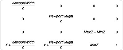
We must first transform the clicked screen point S to point W on the projection window. This is done by working backwards from the equations that transform projection window points to screen points. The viewport transformation matrix used in the equations is shown here:
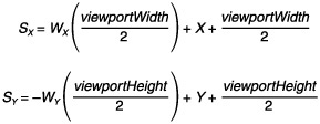
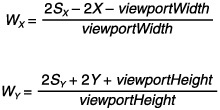
Working backwards, transforming a world space point W (X, Y, Z) by the viewport transformation matrix, yields the screen space point S (X, Y). Following are the two equations to solve for S. The 2D image displayed by your graphics card after rasterization does not contain any depth information (Z).
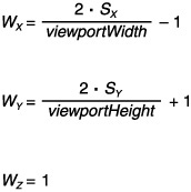
These two equations are great when converting from world space to screen space, but they will serve no purpose unless we can get them into a more useful state. Solving for variable W, we get the following new equations.
The X and Y members of the viewport are almost always 0, so we can go one step further and come up with the following equations. The projection window also coincides with the plane where Z = 1, so we can now set the Z component of the 3D coordinate we are trying to calculate.
There is one last factor that must be considered to correctly solve for W. Different fields of view can be used to present a scene, and the projection matrix scales the points on the projection window to simulate these fields of view. To reclaim the original values before scaling occurs, we must transform the points by the inverse of the scaling operations. The variable projection will be used to signify the projection matrix, and the subscripts represent the matrix entries. Entries 00 and 11 of a transformation matrix scale the X and Y values, so we can produce the following equations.
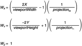
Note
The Managed Direct3D Matrix object uses a slightly different numbering convention for row and column entries. The properties M11 and M22 represent the 00 and 11, respectively.
With the final transformation equations, we can move on to computing the picking ray that will test for objects picked by the user.
A ray can be represented by the parametric equation P(t) = P + t * D, where P is a point in the ray and D is a vector that provides the direction of the ray. In our situation, the origin of the ray is also the origin of the view space, so P = (0, 0, 0). If P is a point on the project window to shoot the picking ray through, then we can solve for D with the following equation.
The following code is used to compute the picking ray for intersection testing.
private PickingRay ComputePickingRay(Entity entity, int x, int y)
{
    float viewportWidth = device.Viewport.Width;
    float viewportHeight = device.Viewport.Height;

    float projection00 = device.Transform.Projection.M11;
    float projection11 = device.Transform.Projection.M22;

    float pX = ((( 2.0F * x) / viewportWidth)  - 1.0F) / projection00;
    float pY = (((-2.0F * y) / viewportHeight) + 1.0F) / projection11;

    Matrix invWorldView = Matrix.Identity;

    invWorldView.Translate(entity.Position);
    invWorldView.Multiply(device.Transform.View);
    invWorldView.Invert();

    Vector3 rayDirection = new Vector3(pX, pY, 1.0f);

    return new PickingRay(rayDirection, invWorldView);
}
After computing the picking ray, we must also transform it into world space to correctly represent the objects in the scene. Transforming the picking ray to world space is done in the constructor of the following struct. The transformation matrix supplied to the constructor is the inverse world-view matrix that was created when the picking ray was computed. The following code is used to transform the picking ray into world space so that the ray and the objects are in the same coordinate system.
internal struct PickingRay
{
    internal Vector3 Origin;
    internal Vector3 Direction;

    public PickingRay(Vector3 direction, Matrix transform)
    {
        Origin = new Vector3(0.0F, 0.0F, 0.0F);
        Direction = direction;

        Origin.TransformCoordinate(transform);
        Direction.TransformNormal(transform);
        Direction.Normalize();
    }
}At this point, we are converting screen space coordinates to world space and computing a ray that will be used for picking. Intersection tests will be performed against objects in the scene using the computed ray to determine which objects the user has selected.
In order to perform intersection tests, we need a 3D shape to test against. Bounding spheres are common because their approximated nature makes them fast to compute and use. Each object is represented by a bounding sphere that describes the approximated volume of the object.
A sphere is represented by its center c and its radius r. Points can be tested for whether they belong to a sphere if their distance from the center is equal to the radius, shown by the following equation.
Intersecting a ray with a sphere can be found with the following equation, where p is substituted with ![]() to represent the ray.
to represent the ray.
We can square both sides of the equation to obtain the following equation.
This equation can then be written as a quadratic equation.
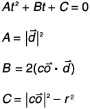
We can calculate the discriminant and use it to determine at first glance whether any solutions exist. Ignoring t, we can calculate the discriminant with ![]() .
.
When the discriminant is less than zero, there are no solutions, so an intersection did not occur.
When the discriminant is equal to zero, there is only one solution, which is generally a tangency. The solution for this case is given by the following equation:
When the discriminant is greater than zero, there are two solutions. Two solutions for this case are given by the following equation:
Rays only extend in one direction (positive), so any solutions where t < 0 have to be ignored. We just need to know if any solution was found, so we can skip the second case altogether and jump right into the third case. If any solution is > 0, we can safely say that an intersection was found.
The following code shows the intersection code for ray-sphere.
private bool IntersectRaySphere(Entity entity, int x, int y)
{
    PickingRay ray = ComputePickingRay(entity, x, y);

    Vector3 vec = ray.Origin - entity.BoundingSphere.Center;
    float b = 2.0F * Vector3.Dot(ray.Direction, vec);

    float center = Vector3.Dot(vec, vec) - (entity.BoundingSphere.Radius *
                                                entity.BoundingSphere.Radius);

    float discriminant = (b * b) - (4.0F * center);

    if (discriminant < 0.0F)
        return false;

    discriminant = (float)Math.Sqrt((double)discriminant);

    float s0 = (-b + discriminant) / 2.0F;
    float s1 = (-b - discriminant) / 2.0F;

    if (s0 >= 0.0F || s1 >= 0.0F)
        return true;

    return false;
}Testing for object intersection with bounding sphere volumes works, and the tests are straightforward and fast to compute. A disadvantage to using bounding sphere volumes is a fair level of inaccuracy. Bounding sphere volumes are ideal for any spherical object, although most of the time intersections are performed against an arbitrary mesh, which means that selections can occur by clicking near the object.
A solution to this problem is to perform triangle intersections against all the polygons within the arbitrary mesh. This process takes longer to compute, but the results are much more accurate than bounding sphere volumes. For the purposes of this example, we will use the built-in Mesh.Intersect() method of Managed Direct3D to perform intersection at the polygon level. The picking ray is computed in the same way as in the previous example, but the picking ray origin and direction are passed into the intersection method.
The following code shows an intersect variation with improved accuracy.
private bool IntersectRayMesh(Entity entity, int x, int y)
{
    PickingRay ray = ComputePickingRay(entity, x, y);
    return entity.Mesh.Intersect(ray.Origin, ray.Direction):
}Reinventing the wheel is generally frowned upon, but a developer can always argue that he would rather reinvent the wheel in some cases if it means he will walk away understanding the mechanics of the solution at a lower level. This chapter has discussed the math and implementation behind converting a screen space coordinate into world space, as well as computing a picking ray that can be used to perform intersection tests against objects. I then went on to showing an improvement to the intersection tests using built-in functionality of the Direct3D Mesh class. There is actually enough built-in functionality with Managed Direct3D to implement a full picking solution with only a few lines of code.
The Vector3 class has a method called Unproject that can be used to project a vector from screen space into world space. We can make two vectors that represent the near and far clipping planes (Z = 0 and 1, respectively), unproject both of them, and then subtract the near vector from the far vector to produce a picking ray suitable for Mesh.Intersect().
The following code shows this.
private bool IntersectUnprojectMesh(Entity entity, int x, int y)
{
    Vector3 near;
    Vector3 far;

    near = new Vector3(x, y, 0);
    far = new Vector3(x, y, 1);

    Matrix world = Matrix.Identity;
    world.Translate(entity.Position);

    near.Unproject(device.Viewport,
                   device.Transform.Projection,
                   device.Transform.View,
                   world);
    far.Unproject(device.Viewport,
                  device.Transform.Projection,
                  device.Transform.View,
                  world);

    far.Subtract(near);
    return entity.Mesh.Intersect(near, far);
}This chapter covered the math and implementation details behind converting screen space coordinates into world space, and performing intersection tests to determine objects that have been picked in a scene.
Remember the following steps:
Given the screen point S, find its corresponding point (W) on the projection window.
Compute the picking ray shooting from the origin through point W.
Transform the picking ray into the same space as each object.
Perform intersection tests to determine the objects picked by the user.
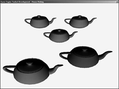
The Companion Web site has the full source code for the example that is fragmented throughout this chapter. The example displays several teapots; the user can click on a teapot and it will turn a different color when selected. Figure 27.2 shows the example provided with this chapter.