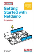
Let’s take a quick look at the MakerShield, shown in Figure 5-1. When you’re prototyping a project for your Netduino, a prototyping shield (such as the MakerShield) can be very useful. This shield provides a prototyping area (a good place to put a tiny breadboard) and also has built-in LEDs, a pushbutton, and a potentiometer (think “volume knob”). The MakerShield is available from Maker Shed at http://www.makershed.com/MakerShield_p/msms01.htm.
Note
If you don’t have a MakerShield, don’t worry: you can plug a pushbutton and LED into a breadboard and then connect the breadboard to the Netduino using a few wires. See Chapter 6 for a complete explanation of breadboards.
To use the MakerShield, simply follow its instructions to solder it together, make sure its jumper is set in the 3.3V position, and then plug it into the top of your Netduino. Its 28 connector legs should be fairly strong—but you should always be a little gentle when inserting them.
In the bottom-left corner of the MakerShield, you’ll notice a 4-pin header with the labels BTN1, LED1, LED2, and POT1 next to it. These header holes are connected to the pushbutton BTN1, to the two LEDs, and to the knob (POT = potentiometer). You’ll use a short piece of solid jumper (or hookup) wire to connect these header holes to the desired digital or analog pin on your Netduino. You can get hookup wire from many places; Maker Shed has a set of deluxe breadboard wires at http://www.makershed.com/product_p/mkseeed3.htm.
In Chapter 3, you created a project that turned on and off an LED every time a button was pushed. In that project, you used the blue LED and the pushbutton on the Netduino itself. Now that you’ve learned about expansion shields, breadboards, and components in Chapter 4, it’s time to use them to connect an external LED and external button to your Netduino. You can also use this exact same code to work with external components.
The original code looked like this:
public static void Main()
{
    // write your code here
    OutputPort led = new OutputPort(Pins.ONBOARD_LED, false);
    InputPort button =
      new InputPort(Pins.ONBOARD_SW1, false, Port.ResistorMode.Disabled);

    bool buttonState = false;

    while (true)
    {
        buttonState = button.Read();
        led.Write(buttonState);
    }
}
Note
Before you modify the project from Pushing the Onboard Button, you might want to make a copy of it. Visual Studio saves your projects in your Documents folder under a folder with a name like Visual Studio 2010Projects. To make a copy of a project, first exit out of Visual Studio, then select the project’s folder, press Control-C, and then press Control-V. If you do this with a project named PushButton1, you’ll end up with a backup copy of it called PushButton1 - Copy. This doesn’t actually change the project name that appears in Visual Studio’s Solution Explorer, though; both copies will have the same name there.
To work with the external LED and pushbutton, you need to change a few lines of code (changes are shown in bold). Open the project again in Visual Studio, then change the line of code that sets up the LED:
OutputPort led = new OutputPort(Pins.GPIO_PIN_D0, false);Next, change the lines of code that sets up the pushbutton:
InputPort button =
  new InputPort(Pins.GPIO_PIN_D1, false, Port.ResistorMode.PullUp);
Note
GPIO means General Purpose Input/Output port. GPIO means that a pin can be used to drive output voltage (3.3V for high, 0V for low) or can be used to interpret the input voltage (3.3V for high, 0V for low).
You changed the LED to pin “digital 0” and changed the pushbutton to
pin “digital 1.” That’s fairly straightforward. But why did I have you
change the ResistorMode for the
pushbutton?
Pushbuttons can be wired many different ways. In one configuration, they drive the voltage high when pushed. In another popular configuration (used on the MakerShield), they drive the voltage low when pushed. Since a digital input is neither high nor low by default, you need to provide a default of high so that the MakerShield’s button can drive the signal low when pushed.
By specifying ResistorMode.PullUp, you instruct the Netduino’s
microcontroller to put a tiny bit current on the pin, which makes it
default to high; when the pushbutton is pressed, it overrides this signal
with a strong connection to ground (0V).
Since the pushbutton will give you a reading of false (0V) when it’s
pressed, you need to reverse the logic in your code so that the LED lights
up when the button is pressed and not vice versa. To do this, you must
modify one more line of code, which you’ll find inside the while loop:
buttonState = !button.Read();The difference in code may seem insignificant and is easy to miss. I
had you add an exclamation mark directly in front of the word button. In C# code, an exclamation mark means
“not” or “the opposite of” a true/false (Boolean) value. If button.Read() returns false (because it is
pushed), you want to invert that so that the button state reads true
(indicating that it was pushed).
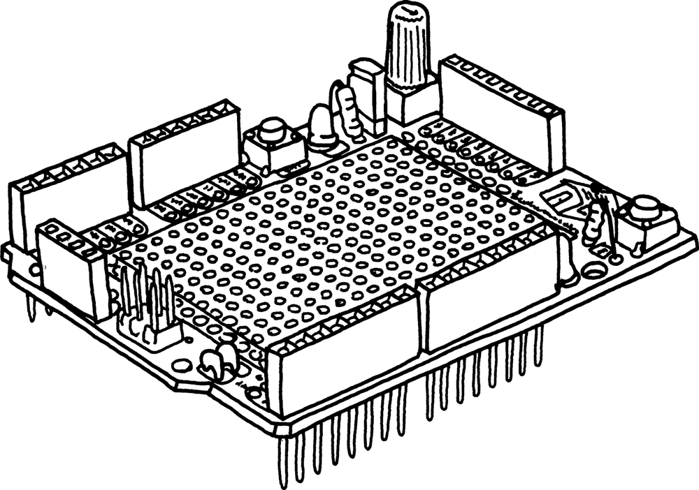
The final thing you need to do is wire up the pushbutton and LED. To do this, connect a short piece of wire between digital header pin D0 on the MakerShield and the header hole labeled LED1 or LED2 (either one is fine). Also, connect a short piece of wire between digital header pin D1 on the MakerShield and the header hole labeled BTN1. Figure 5-2 shows how to hook things up.
Note
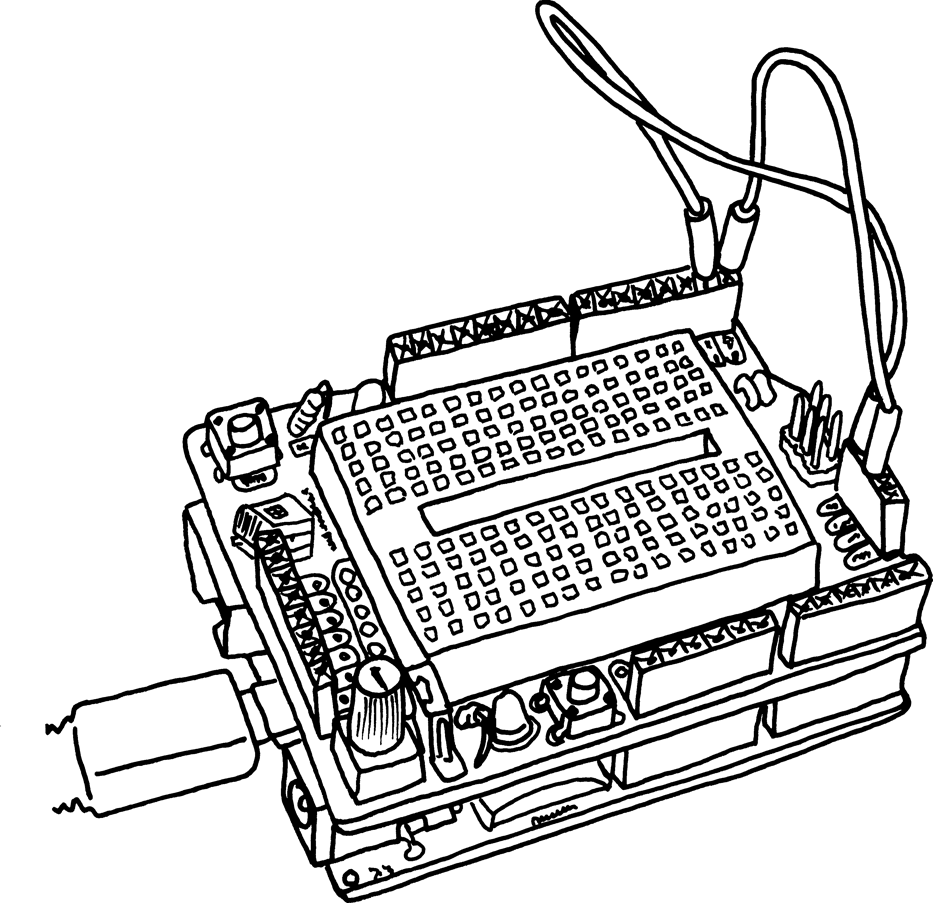
If you don’t have a MakerShield, you can still lay out this project on a breadboard. Figure 5-3 shows how you’d lay it out on a breadboard (for the resistor, you can use one with a value between 150 and 330 ohm).
Now run your project as you did in Chapter 3. Press the Start Debugging button in the toolbar at the top of the screen (or press F5).
When you press the pushbutton on your MakerShield, the LED will turn on; release the pushbutton and it will turn off.