
Create a new project as before and open the Program.cs file in the main code editing window.
Now, type the following:
PWM led = new PWM(Pins.GPIO_PIN_D5);AnalogInput pot = new AnalogInput(Pins.GPIO_PIN_A0);
pot.SetRange(0, 100); int potValue = 0;
-
This line of code creates a PWM object using our digital pin D5. This lets you control the intensity of the LED by changing its duty cycle (percentage of time turned on vs. off).
-
The second and third lines of code set up the potentiometer as before, but this time with a range of 0 through 100. This will give you a percentage that you can use to set the LED’s intensity.

This line creates a variable named
potValue, which you’ll use to store and retrieve the potentiometer’s current position.
Now you need to write some code to change the LED’s intensity based on the value of the potentiometer. Add the following:
while (true)
{
// read the value of the potentiometer
potValue = pot.Read();
// change the led intensity based on
// the potentiometer's value (0-100%)
led.SetDutyCycle((uint) potValue);
}Your final code will look like this:
public static void Main()
{
// write your code here
PWM led = new PWM(Pins.GPIO_PIN_D5);
AnalogInput pot = new AnalogInput(Pins.GPIO_PIN_A0);
pot.SetRange(0, 100);
int potValue = 0;
while (true)
{
    // read the value of the potentiometer
    potValue = pot.Read();

    // change the led intensity based on
    // the potentiometer's value (0-100%)
    led.SetDutyCycle((uint) potValue);
}
}Now run the project on your Netduino (don’t forget to set the deployment target using the project’s properties dialog first). Turn the potentiometer’s knob to the left, to the center, and all the way to the right. Watch how the brightness of the LED changes as you adjust the knob.
Note
Digital pins D5, D6, D9, and D10 can all be used as PWM-enabled pins.
Every dot on a television, computer monitor, or phone screen can display one of many thousands (or millions!) of colors. This is generally done by mixing tiny red, green, and blue pixels together. By blending various intensities of each of these three basic colors, you can display a whole spectrum of colors. Let’s do so now.
For this example, you’ll need an RGB LED. This is an LED with red, green, and blue LED elements inside of it. It will generally have four legs: one positive input leg for each of the three colors and one negative output leg for ground. The negative (longest) leg is called the common cathode. There are also common anode versions of RGB LEDs that you can use with Netduino, but they need to be wired in reverse and use inverse programming logic.
Since each colored LED element needs its own resistors, you’ll wire up resistors between the microcontroller and the RGB LED on this example.
Note
Resistors can be placed either before or after the LED in a circuit. They will limit the amount of power driven through the resistors either way. But you must make sure to include them, or you risk damaging the LED. In the case of RGB LEDs, the resistors must be added to the anode side as we have done here.
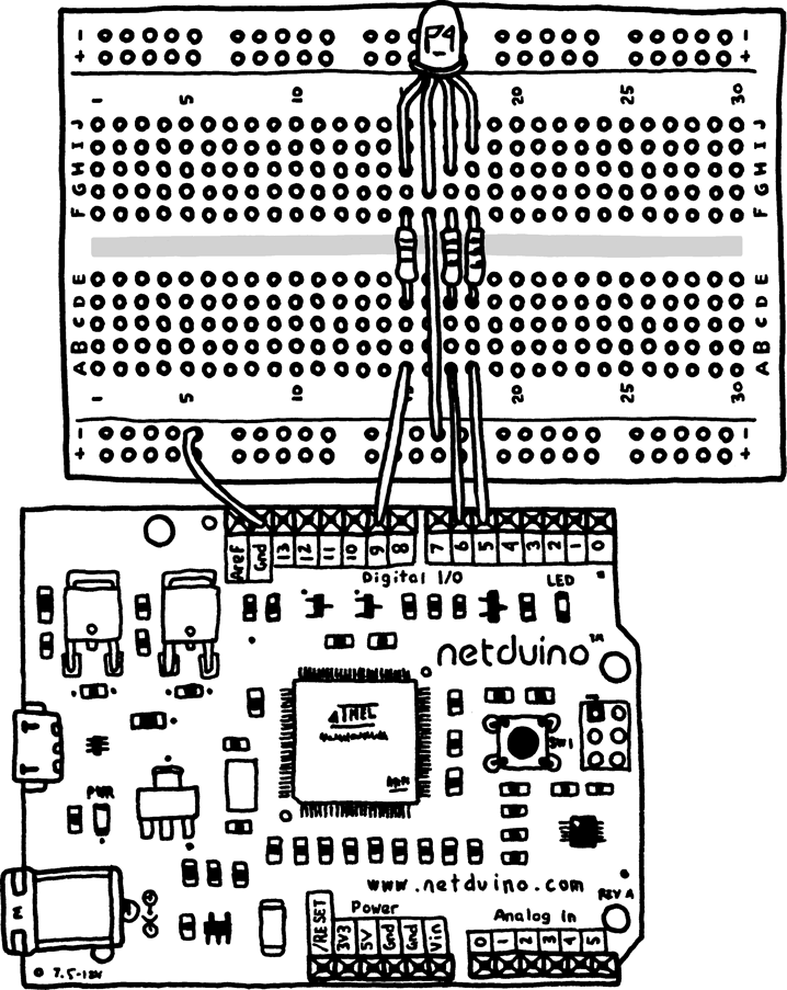
Plug an RGB LED into a breadboard. Make sure all four legs are plugged into different rows. Connect a wire between the negative (longest) leg and the ground rail.
Now, connect a resistor between each of the three RGB positive legs and a separate row on the other side of the breadboard’s middle divider. Finally, connect a wire between each of those rows and a digital pin on the Netduino. Use digital pins D5, D6, and D9 on the Netduino.
Now you’re ready to write some code to display the color purple. Start out by typing the following:
PWM redLed   = new PWM(Pins.GPIO_PIN_D9);
PWM greenLed = new PWM(Pins.GPIO_PIN_D6);
PWM blueLed  = new PWM(Pins.GPIO_PIN_D5);
These three lines of code will set up the
redLed, greenLed, and
blueLed objects. Those PWM objects will let you
control the intensity of each of our three LEDs.
Don’t worry if you’re not sure if the red, green, and blue LEDs are plugged into the correct digital pins. If they’re arranged in the wrong order, you can swap them around in a few moments. However, many RGB LEDs are laid out in the way shown in Figure 6-2: R, common cathode, G, B.
Continue by setting the colors to the intensities for the color purple:
// change the color intensities
redLed.SetDutyCycle(60);    // 60% red intensity
greenLed.SetDutyCycle(0);   // 0% green intensity
blueLed.SetDutyCycle(100);  // 100% blue intensity
Finally, add a line of code that puts the program to sleep indefinitely. This makes it so that your program doesn’t just stop running.
// go to sleep
Thread.Sleep(Timeout.Infinite);
Your final code will look like this:
public static void Main()
{
    // write your code here
    PWM redLed   = new PWM(Pins.GPIO_PIN_D9);
    PWM greenLed = new PWM(Pins.GPIO_PIN_D6);
    PWM blueLed  = new PWM(Pins.GPIO_PIN_D5);

    // change the color intensities
    redLed.SetDutyCycle(60);    // 60% red intensity
    greenLed.SetDutyCycle(0);   // 0% green intensity
    blueLed.SetDutyCycle(100);  // 100% blue intensity

    // go to sleep
    Thread.Sleep(Timeout.Infinite);
}
Now run the program. If you see the color purple, congratulations! Stop the program, change the intensity values to different percentages, and run it again. You’ll discover a whole world of colors.
If the color is incorrect, stop the program. Change the intensity of one color to 100 and the other two colors to 0. Rerun the program. If the wrong LED lights up, swap the three wires between D5/D6/D9 until the correct colors light up. Then repeat for the next color(s). Your colors should now be wired up correctly.
Note
You can look up the red, green, and blue intensity values for colors with an online color calculator. One such resource is http://www.rapidtables.com/web/color/RGB_Color.htm.