2
HSDPA and HSUPA in Release 5 and 6
Antti Toskala
2.1 Introduction
This chapter presents the Release 5 based High Speed Downlink Packet Access (HSDPA) and Release 6 based High Speed Uplink Packet Access (HSUPA). This chapter looks first at the 3GPP activity in creating the standard and then presents the key technology components introduced in HSDPA and HSUPA that enabled the breakthrough of mobile data. Basically, as of today, all networks have introduced as a minimum HSDPA support, and nearly all also HSUPA. Respectively, all new chip sets in the marketplace and all new devices support HSDPA and HSUPA as the basic feature set. This chapter also addresses the network architecture evolution from Release 99 to Release 7, including relevant core network developments.
2.2 3GPP Standardization of HSDPA and HSUPA
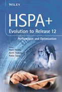
3GPP started working on better packet data capabilities immediately after the first version of the 3G standard was ready, which in theory offered 2 Mbps. The practical experience was, however, that Release 99 was not too well-suited for more than 384 kbps data connections, and even those were not provided with the highest possible efficiency. One could have configured a user to receive 2 Mbps in the Dedicated Channel (DCH), but in such a case the whole downlink cell capacity would have been reserved to a single user until the channel data rate downgraded with RRC reconfiguration. The first studies started in 2000 [1], with the first specification in 2002 for HSDPA and then 2004 for HSUPA, as shown in Figure 2.1.
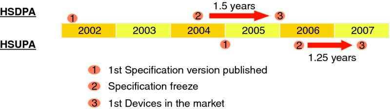
Figure 2.1 3GPP HSDPA and HSUPA specification timeline
While the Release 99 standard in theory allows up to 2 Mbps, the devices in the field were implemented only up to 384 kbps. With HSDPA in Release 5 the specifications have been followed such that even the highest rates have been implemented in the marketplace, reaching up to 14 Mbps, and beyond this in later Releases with different enhancements, as covered in the later chapters of this book. The first HSDPA networks were opened at the end of 2005 when the first data products appeared in the marketplace, some 18 months after the 3GPP specification freeze.
With HSUPA, commercial implementations appeared in the marketplace in mid-2007, some 15 months after the specification freeze of early 2006, as shown in Figure 2.1. With smart phones it took generally a bit longer for the technology to be integrated compared to a USB dongle-style product.
The Release 6 uplink with HSUPA including up to 5.8 Mbps capability has also been widely implemented, while the uplink data rate has also been enhanced beyond the Release 6 capability in later 3GPP Releases.
2.3 HSDPA Technology Key Characteristics
The Release 99 WCDMA was basically very much circuit switch oriented in terms of resource reservation, which restricted the practical use of very high data rates while amply providing the CS services (voice and video) that did not require a too high bit rate [2]. The Release 5 HSDPA included several fundamental improvements to the WCDMA standard, with the key items being:
- BTS based scheduling;
- physical layer retransmissions;
- higher order modulation;
- link adaptation;
- dynamic code resource utilization.
BTS-based scheduling moved the scheduling of the common channels from the RNC to the BTS, closer to the radio with actual knowledge of the channel and interference conditions and resource availability. While the scheduling for HSDPA was moved to the BTS, lots of other intelligence remained in the RNC, and further HSDPA functionalities were in most cases additional functionalities, not replacing RNC operation. The Release 99 functional split for the radio resource management is shown in Figure 2.2.
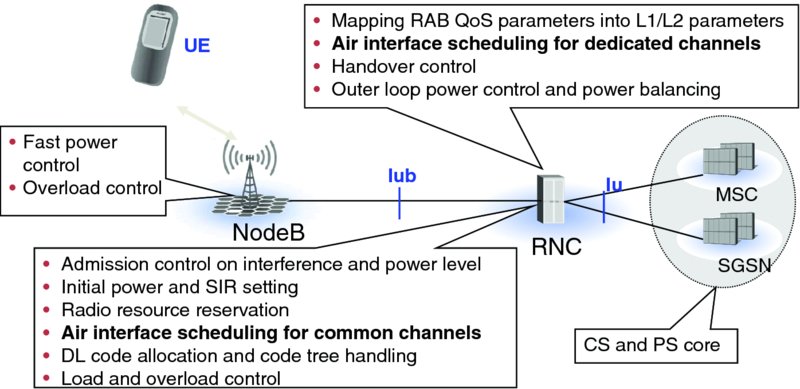
Figure 2.2 Release 99 radio resource management functional split
From the protocol stack point of view, the new functionality is added to the MAC layer, with the new MAC-hs added in the BTS. This is illustrated in Figure 2.3, with the remaining MAC-d in the RNC responsible for possible MAC layer service multiplexing.
Figure 2.3 HSDPA user plane protocol stack
BTS-based link adaptation allowed reaction to the momentary downlink link quality with all the information of the radio link situation available in the BTS via the new physical layer Channel Quality Information (CQI) feedback. When a user comes closer to the BTS, the received power level is better than needed. This is due to the limited downlink power control dynamic range, since signals received by the users cannot have too large a power difference. This means that a user close to the BTS has a symbol power level tens of dBs greater than necessary. This excessive symbol power level is utilized with the link adaptation. For a user in a good link quality situation, higher order modulation and less channel coding can be used. Respectively, for a user with lower link quality, more robust modulation and more channel encoding redundancy can be used for increased protection. This is illustrated in Figure 2.4.
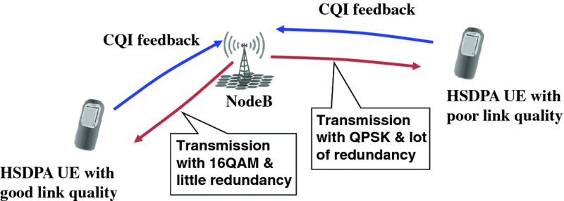
Figure 2.4 HSDPA link adaptation
The link adaptation thus ensures successful transmission even at the cell edge. When data first arrives at the buffer in the base station, the base station scheduler will, however, first prefer to check that the UE has good link condition. Normally, the link condition changes all the time, even for a stationary user. By placing the transmissions in such time instants, based in the CQI, the resource usage is minimized and the system capacity is maximized. The time window considered in the base station varies depending on the service requirements. The detailed scheduler implementation is always left for the network implementation and is not part of the 3GPP specifications.
Transmission of a packet is anyway not always successful. In Release 99 a packet error in the decoding would need a retransmission all the way from the RNC, assuming the Acknowledged Mode (AM) of RLC is being used. Release 5 introduced physical layer retransmission enabling rapid recovery from an error in the physical layer packet decoding.
The operation procedure for the physical layer retransmission is as follows:
- After transmission a packet is still kept in the BTS memory and removed only after positive acknowledgement (Ack) of the reception is received.
- In case the packet is not correctly received, a negative acknowledgement (NAck) is received from the UE via the uplink physical layer feedback. This initiates retransmission, with the base station scheduler selecting a suitable moment to schedule a retransmission for the UE.
- The UE receiver has kept the earlier packet in the receiver soft buffer and once the retransmission arrives, the receiver combines the original transmission and retransmission. This allows utilization of the energy of both transmissions for the turbo decoder process.
- The Hybrid Adaptive Repeat and reQuest (HARQ) operation is of stop and wait type. Once a packet decoding has failed, the receiver stops to wait for retransmission. For this reason one needs multiple HARQ processes to enable continuous operation. With HSDPA the number of processes being configurable, but with the UE memory being limited, the maximum data rate is achieved with the use of six processes which seems to be adapted widely in practical HSDPA network implementations.
The HSDPA HARQ principle is shown in Figure 2.5. From the network side, the extra functionality is to store the packets in the memory after first transmission and then be able to decode the necessary feedback from the UE and retransmit. Retransmission could be identical, or the transmitter could alter which bits are being punctured after Turbo encoding. Such a way of operating is called incremental redundancy. There are also smaller optimizations, such as varying the way the bits are mapped to the 16QAM constellation points between retransmissions. The modulation aspects were further enhanced in Release 7 when 64QAM was added. While the use of 16QAM modulation was originally a separate UE capability, today basically all new UEs support 16QAM, many even 64QAM reception as well.
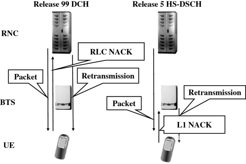
Figure 2.5 HSDPA HARQ operation
To address the practicality of handling high bit rates, dynamic code resource sharing was introduced. Release 99 UE was allocated a specific downlink channelization code(s) dimensioned to carry the maximum data rate possible for the connection. When the data rate was smaller, the transmission was then discontinuous to reduce interference generated to the network. Thus, with the lower data rates, the code was then used only part of the time, as shown in Figure 2.6. It is not possible to share such a resource with any other user, which causes the orthogonal code resource to run out quickly, especially with the case of variable rate packet data connections. Had one used 2 Mbps in the field, it would have basically enabled only a single user to have been configured in a cell at the time.
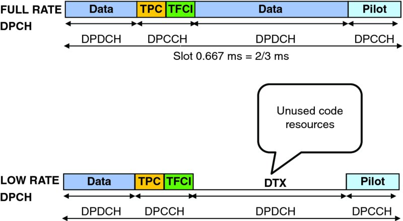
Figure 2.6 Code resource usage with Release 99 DPCH
The dynamic code resource utilization with HSDPA means that for each packet there is separate control information being transmitted (on the High Speed Shared Control Channel, HS-SCCH), which identifies which UE is to receive the transmission and which codes are being used. When a UE does not have downlink data to receive on HSDPA, the codes are used by another user or users. There is a pool of 15 codes with a spreading factor of 16 available for HSDPA use, assuming that there is not too much other traffic, such as Release 99 based voice, requiring codes for DCH usage. One cell can have up to four parallel HS-SCCHs which UE could monitor, but for maximum performance it is usually better to send to fewer users at a time in order to minimize the overhead needed for the signaling. From a network point of view, one could configure even more than four HS-SCCHs for one cell, giving different UEs a different set of the channels, but there is no real benefit from such a configuration. The principle of the use of HS-SCCH to point out to the UE which High Speed Physical Shared Channel (HS-PDSCH) codes to receive is illustrated in Figure 2.7. As seen also in Figure 2.6 there is a timing offset between the control and data channel, which allows the UE to determine before the 2 ms Transmission Time Internal (TTI) on HS-PDSCH which codes are intended for the UE in question. This needs to be known beforehand, especially if the UE receiver is able to receive fewer codes than the maximum of 15.

Figure 2.7 HSDPA physical channels for data and control
The HS-SCCH is divided into two parts, with the first part carrying information on the codes received and also which modulation is being used, while the second part carries information on the HARQ process being used, transport block size, redundancy version or whether the transmission is new packet, or whether it should be combined with existing data in the buffer for the particular HARQ process. The spreading factor for HS-SCCH is always fixed to be 128, and UE will check from the first part whether the control data is intended for it or not (UE specific masking prevents successful decoding of another HS-SCCH than the one intended for the UE).
The structure for the HS-PDSCH is simple, as there are only symbols carrying user data, not control fields or pilot symbols. The number of channel bits fitting on a single code on HS-PDSCH is only impacted by the modulation being used, with the alternatives being QPSK and 16QAM from Release 5 or additionally the use of 64QAM as added in Release 7. Up to 15 codes may be used in total during a 2-ms TTI, as shown in Figure 2.8. The channel coding applied on the HS-PDSCH is turbo coding.
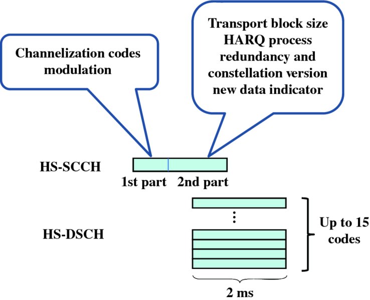
Figure 2.8 HS-SCCH structure
Besides downlink control information, there is also the need to transmit uplink physical layer control information for HSDPA operation. For that purpose a new physical channel was added in the uplink direction as well, the High Speed Dedicated Physical Control Channel (HS-DPCCH). The HS-DPCCH carries the physical layer uplink control information as follows:
- Feedback for the HARQ operation, information on whether a packet was correctly decoded or not, thus carrying positive and negative acknowledgements. In later phases, different post/preambles have also been added to avoid NodeB having to decide between the ACK/NACK and DTX state, thus improving the detection reliability.
- Channel Quality Information (CQI) helps the base station scheduler to set correct link adaptation parameters and decide when is a good moment to schedule the transmission for a particular user. The CQI basically gives from the UE an estimate of what kind of data rate could be received reliably in the current conditions the UE is experiencing. Besides the external factors, such as interference from other cells and relative power of the own cell (serving HSDPA cell), the CQI also covers UE internal implementation aspects, such as whether there is an advanced receiver or whether the UE has receiver antenna diversity.
The network can parameterize the HS-DPCCH to also use different power offsets for the different fields carrying CQI and ACK/NACK feedback, as shown in Figure 2.9. It is also worth noting that the HS-DPCCH is never transmitted on its own, but always in connection with the uplink DPCCH. Uplink DPCCH contains pilot symbols and thus provides the necessary phase reference for the NodeB receiver. Besides pilot symbols, the uplink DPCCH carries the downlink power control commands and the Transport Format Combination Indication (TFCI) to inform on the data rate being used on the uplink Dedicated Physical Data Channel (DPDCH). If only HSDPA is operated without HSUPA, all uplink user data is then carried on DPDCH.

Figure 2.9 HS-DPCCH carrying ACK/NACK and CQI feedback
The CQI information does not map directly to a data rate but actually provides an indication of the transport block size, number of codes, and level of modulation which the terminal expects it could receive correctly. This in turn could be mapped to a data rate for the assumed power available for HSDPA use. Depending on the type of UE, the CQI table covers only up to such modulation which the UE can support, after that an offset value is used. For this reason there are multiple CQI tables in [2]. In the first phase of HSDPA introduction the UEs on the market supported only QPSK modulation, but currently the generally supported modulations also include 16QAM, and in many cases also 64QAM. The values indicated by the CQI are not in any way binding for the NodeB scheduler; it does not have to use the parameter combination indicated by the CQI feedback. There are many reasons for deviation from the UE feedback, including sending to multiple UEs simultaneously or having actually different amounts of power available for HSDPA than indicated in the broadcasted value.
2.4 HSDPA Mobility
The mobility with HSDPA is handled differently from Release 99 based DCH. Since the scheduling decisions are done independently in the NodeB scheduler to allow fast reaction to the momentary channel conditions, it would be difficult to follow the Release 99 soft handover (macro diversity) principle with combining time aligned identical transmission from multiple BTS sites. Thus the approach chosen is such that HSDPA data is only provided from a single NodeB or rather by a single cell only, called the serving HSDPA cell. While the UE may still have the soft handover operation for DCH, the HSDPA transmission will take place from only a single NodeB, as shown in Figure 2.10.
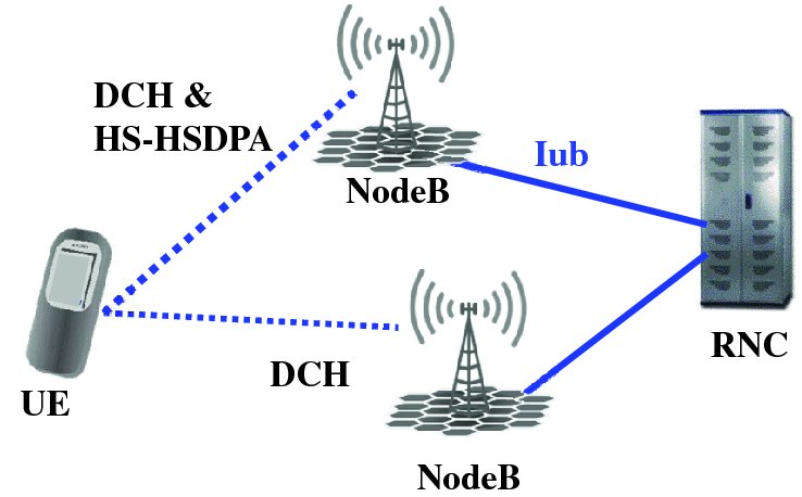
Figure 2.10 Operation of HSDPA from a single NodeB only with DCH soft handover
When operating within the active set, the UE shall signal the change of the strongest cell and then the serving HSDPA cell can be changed to another NodeB. If the strongest cell is not part of the active set, then the new cell needs to be added to the active set before HSDPA transmission can take place from that cell. When changing the serving HSDPA cell, the packets in the source NodeB buffer are thrown away once the serving cell change is complete and the RNC will forward the packets not received to the new serving HSDPA cell NodeB, in case Acknowledged Mode (AM) operation of RLC is being used.
2.5 HSDPA UE Capability
In Release 5 a total of 12 UE categories were defined supporting up to 14 Mbps downlink peak data rate. Some of the UE categories were based on the possibility of having the UE receiving data not during consecutive TTIs, but in reality that possibility has not been utilized. In the first phase the products in the market had only QPSK modulation supported, enabling only 1.8 Mbps physical layer peak data rate, but soon implementations with 16QAM also became available enabling first 3.6 Mbps and then later up to 7.2 Mbps or even up to 10 or 14 Mbps. The relevant UE categories, which actually have been introduced to the market in wider scale, are shown in Table 2.1, with all categories given in [3]. The RLC data rates are calculated with 40 bit RLC packet size. In Release 7 3GPP introduced a flexible RLC packet size which allows reduction of the RLC header overhead.
Table 2.1 Release 5 HSDPA UE categories and their L1/RLC peak data rates
| Highest | Max L1 data rate | Max RLC data rate | ||
| UE category | # of codes | Modulation | (Mbps) | (Mbps) |
| 12 | 5 | QPSK | 1.8 | 1.6 |
| 5/6 | 5 | 16QAM | 3.6 | 3.36 |
| 7/8 | 10 | 16QAM | 7.2 | 6.72 |
| 9 | 15 | 16QAM | 10.7 | 9.6 |
| 10 | 15 | 16QAM | 14.0 | 13.3 |
2.6 HSUPA Technology Key Characteristics
While Release 5 HSDPA introduced a significant boost to downlink packet data capabilities, the uplink operation was unchanged for user data. There were only modifications to cover the necessary uplink feedback with HSDPA operation. The problem areas in the uplink direction were not exactly the same, but fundamentally the Release 99 based design in uplink was more suited for continuous and relatively low rate data transmission than for high bit rate packet data operation. With RNC-based uplink scheduling using the uplink DCH, up to 384 kbps were only implemented in the commercial UMTS networks. If the capacity of the Release 99 network was roughly around 1 Mbps per sector, one could only have allocated roughly three 384 kbps users. With the variable data rate connection the allocated maximum data rate would basically reserve the sector capacity and could only be controlled slowly by the RNC.
To improve the situation, 3GPP introduced in Release 6 with the HSUPA several improvements addressing the following areas that were introduced following study [4]:
- BTS scheduling/ rate control;
- link adaptation;
- HARQ;
- shorter frame size.
With the BTS scheduling and rate control the key target was to address the burstiness of the uplink data transmission needs. The UE provides feedback for the NodeB on the power resources available as well as on the uplink transmission buffer status. This enables the NodeB to allocate more uplink transmission “allowance” for such UE which has more data in the buffer, and then the allocation can be respectively reduced from a UE that does not have that high transmission need. This principle is illustrated in Figure 2.11.
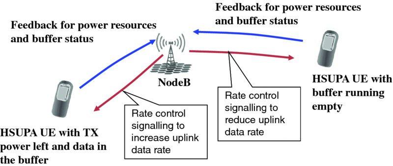
Figure 2.11 Uplink NodeB scheduling principle with HSUPA
From the protocol point of view, the new intelligence in NodeB is part of the MAC-e – with “e” standing for enhanced. Since the uplink transmission is controlled, the UE has a new entity in the MAC layer, as shown in Figure 2.12.
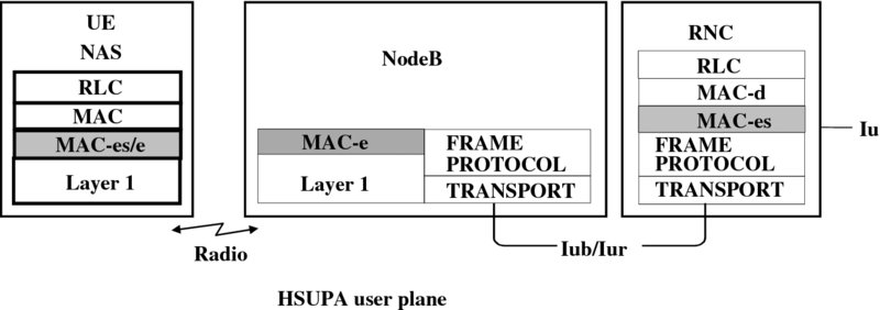
Figure 2.12 HSUPA user place protocol stack new elements
With HSUPA there is also the new MAC entity in the RNC, called MAC-es. Since the uplink macro-diversity operation is retained with HSUPA, there can be more than a single NodeB receiving the uplink packet transmission, as shown in Figure 2.13. In this case a packet transmitted earlier may fail in the decoding in all of the NodeBs in the active set while a packet transmitter is later decoded correctly with first transmission. This, together with the physical layer retransmissions, creates the need for packet re-ordering in the RNC side to restore the order of packets before they are provided to the higher layers.
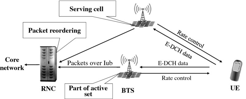
Figure 2.13 HSUPA operation in soft handover
The rate control in Figure 2.13 can be implemented with two alternative methods, either by using relative grants which basically move the data rate up or down, a bit similar to power control operations. Or the other approach is the use of an absolute grant which enables moving to any possible data rate for the connection (but addressing then only a single UE at a time). Handling the rate control in the NodeB allows reaction to the bursty nature of the application, and avoids having to reserve uplink capacity according to the maximum data rate, thus effectively narrowing the uplink noise rise variance and enabling loading the uplink more fully compared to the Release 99 based uplink solution, as shown in Figure 2.14.
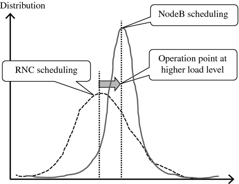
Figure 2.14 Noise rise distribution with RNC and NodeB based uplink schedulers
The following channels were introduced in the downlink direction to control the HSUPA operation:
- The Enhanced DCH Relative Grant Channel (E-RGCH) is used to transfer relative grants to control the uplink effective data rate up or down. The channel is not heavily coded as a decoding error simply causes the data rate to move to another direction. The NodeB receiver in any case reads the rate information before decoding, thus there is no resulting error propagation.
- The Enhanced DCH Absolute Grant Channel (E-AGCH) is used to transfer absolute grants. E-AGCH is more strongly coded and protected with CRC since a decoding error could cause a UE to jump from the minimum data rate to the maximum data rate. Respectively only one UE can be controlled at a time per E-AGCH.
- The Enhanced DCH HARQ Indicator channel (E-HICH) is used to inform the UE whether the uplink packet has been received correctly or not, since there is similar physical layer retransmission procedure introduced with HSUPA as with HSDPA.
In the uplink direction the following new channels were introduced:
- The E-DCH Dedicated Physical Control Channel (E-DPCCH) carries the control information related to the uplink transmission. The E-PDCCH has the Retransmission Sequence Number for HARQ, happy bit, and the Enhanced Transport Format Combination Indicator (E-TFCI). The happy bit indicates whether the UE could use a higher data rate in the uplink direction. If the UE is limited either by the uplink power resource or by the amount of data in the uplink transmission buffer and is thus not able to use higher data rate, then the UE is considered to be happy. The scheduling information, part of the MAC Payload Data Unit (PDU), carries then more detailed information of the buffer status and power headroom situation. E-TFCI indicates the data rate being on used the E-DPDCH.
- The E-DCH Dedicated Physical Data Channel (E-DPDCH) carries the actual data. There is no physical layer control information nor pilot symbols on E-DPDCH. The channel estimation is based on the pilot symbols on the uplink DPCCH which is always transmitted in parallel to the E-DCH channels. The E-DCH can use two frame durations, 2 ms and 10 ms. All the control channels will then do the same, typically the solution being repeating the 2 ms structure five times (in some cases only four times in the downlink from the other cells in the active set); the set of channels introduced with HSUPA are shown in Figure 2.15. Similarly to the HS-PDSCH, E-DPDCH also uses only turbo coding.
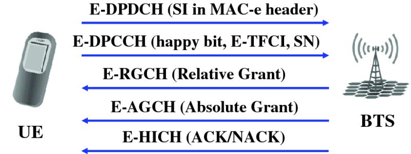
Figure 2.15 New physical channels introduced with HSUPA
The E-DPDCH carrying the actual data may use the spreading factor from 256 to as low as 2, and then also multicode transmission. Since a single code on the E-DPDCH is using basically only the I or Q branch, there are two code trees then usable under a single scrambling code. Thus the peak data (without 16QAM) of 5.7 Mbps is obtained with the use of two spreading codes with spreading factor 2 and two codes with spreading factor 4. The network may select which of the TTI values will be used, with 10 ms being better for coverage while 2 ms TTI offers larger data rates. The TTI in use may be changed with the reconfiguration.
Originally the uplink modulation was not modified at all, since the use of QPSK (Dual-channel BPSK), as covered in [2], has lower energy per bit than use of higher order modulation such as 16QAM (which was introduced in Release 7). While in downlink direction the limited power control dynamic range causes devices to receive the signal with too good SINR when close to NodeB (“high geometry” region), the use of 16QAM or 64QAM comes more or less for free. In the uplink direction the power control dynamic range can be, and has to be, much larger to avoid the uplink near-far problem. The uplink fast closed-loop power control operates as in Release 99, based on the uplink DPCCH signal received as well as typically monitoring the packet decoding performance (Block Error Rate, BLER). Therefore the uplink signal received by the NodeB from the UE does not arrive with too high a power level, and thus changing to higher order modulation only increases the interference level for other users for a given data rate. The only situation when the use of 16QAM (or higher) modulation would make sense would be a single user per cell situation. In such a case higher order modulation allows an increase in the peak data rate that is available with the uplink code resources under a single scrambling code. As discussed in Chapter 8, the use of an advanced BTS receiver can deal with the interference from other HSUPA users.
The physical layer HARQ operation with HSUPA uses a fixed number of HARQ processes, with four processes used with 10-ms TTI, as shown in Figure 2.16. With a single transmission error there is 30-ms time between the original and retransmission and thus 40 ms of extra delay involved for a single retransmission. There is 14 to 16-ms time for a NodeB to decode the uplink packet and to determine if ACK/NACK needs to be transmitted. The range is due to the downlink channel timing being set on 2-ms intervals as a function of the uplink timing. With 2-ms TTI there are eight processes in use, thus the extra delay for a single retransmission is 16 ms, with the respective NodeB and UE processing times shown in Figure 2.17. The times are shortened, which is partly compensated for as the - ms TTI has less room for channel bits due to shorter duration.
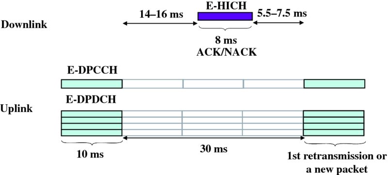
Figure 2.16 HSUPA uplink/downlink timing relationship with 10-ms TTI
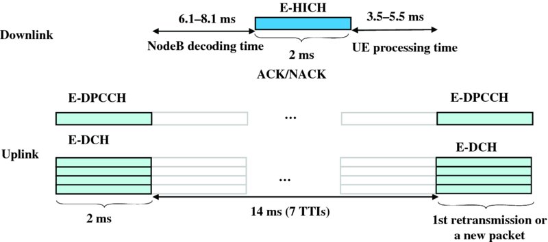
Figure 2.17 HSUPA uplink/downlink relationship with 2-ms TTI
2.7 HSUPA Mobility
With HSUPA the active set is operated as in Release 99, with all the base stations in the active set normally receiving the HSUPA transmission. However, there is only one serving cell (the same cell as providing the HSDPA data) which has more functionalities as part of the rate control operation for the scheduling. Only the serving HSUPA cell will send the absolute grants or relative grants which can increase the data rate. The other NodeBs in the active set will only use relative grants to reduce the data rate if experiencing interference problems, as shown in Figure 2.18. All NodeBs in the active set try to decode the packets and will then send feedback on the E-HICH if packets were decoded correctly.
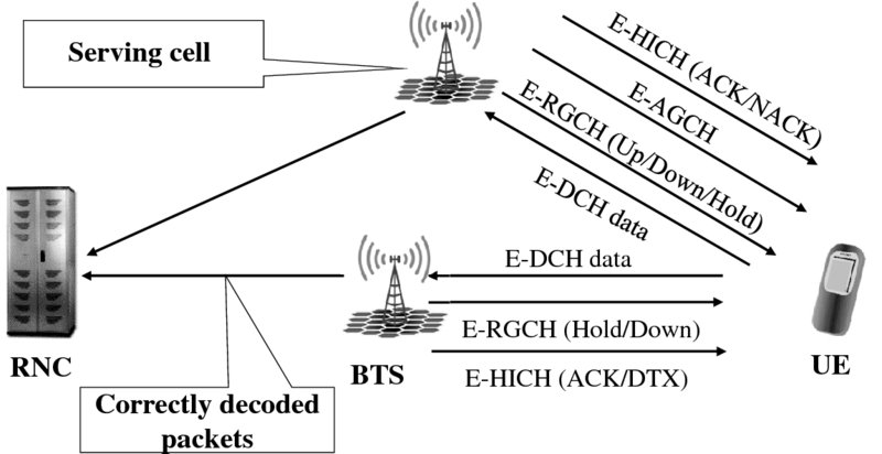
Figure 2.18 HSUPA control channel operation with mobility
In general, the soft handover overhead, from the backhaul point of view, is also smaller with HSUPA as with Release 99. The HSUPA operation does not cause packets with decoding errors to be sent for RNC as the physical layer asks for retransmission and only correctly decoded packets are then provided for the MAC-es in the RNC for reordering.
2.8 HSUPA UE Capability
The HSUPA UE capability with the latest products typically reaches category 6, enabling 5.76 Mbps uplink peak data rate in the physical layer, as shown in Table 2.2. In the early phase of HSUPA introduction, the equipment in the field typically supported only 10-ms TTI which enabled a 2 Mbps uplink peak data rate. In later Releases new categories were then added with the introduction of 16QAM in the uplink and 64QAM in Release 11, as can be seen from Release 11 version of [3].
Table 2.2 HSUPA UE capability in Release 6 and 7
| Max L1 data rate (Mbps) | |||
| UE category | # of codes | 10-ms TTI | 2-ms TTI |
| 1 | 1 × SF4 | 0.73 | — |
| 2 | 2 × SF4 | 1.46 | 1.46 |
| 3 | 2 × SF4 | 1.46 | — |
| 4 | 2 × SF2 | 2.0 | 2.9 |
| 5 | 2 × SF2 | 2.0 | — |
| 6 | 2 × SF2 + 2 × SF4 | 2.0 | 5.76 |
| 7(16QAM) | 2 × SF2 + 2 × SF4 | 2.0 | 11.5 |
2.9 HSPA Architecture Evolution
HSDPA was the first step towards moving more functionality towards the NodeB, with a first step being the downlink scheduling functionality taken away from the RNC and moved to the NodeB. Still, a lot of the Release 99 based functionality remained in the RNC after Release 5 had moved the downlink packet scheduling and Release 6 the uplink packet scheduling control to the NodeB. Architecture evolution continued with 3GPP introducing in Release 7 a further fully flat radio architecture option with all the radio functionality, including RRC signaling, moved to the NodeB, as shown in Figure 2.19. This was then later also adopted to be the LTE radio protocol architecture solution as well [5]. From the core network point of view, also the user plane traffic was moved to bypass the Serving GPRS Support Node (SGSN), with the control plane still going through the SGSN.
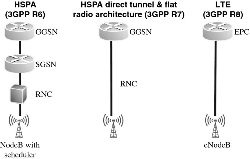
Figure 2.19 HSPA architecture evolution for user plane
From the control plane point of view, the signaling towards the core network goes via the SGSN, similar again to the LTE control plane solution with the Mobility Management Entity in LTE being a control plane only element in the core network side, with the LTE core network known as the Evolved Packet Core (EPC).
A further important aspect is the backhaul, since with HSDPA and HSUPA the backhaul transmission resources are not reserved on a user basis according to the peak data rate, thus leading to much better multiplexing gain in the HSPA backhaul network. The backhaul dimensioning for HSDPA has been studied in [6].
2.10 Conclusions
In this chapter the fundamental HSPA functionality introduced in Release 5 and 6 was covered, enabling the end users to reach the original 3G dream of 2 Mbps data rate availability. The basic HSPA features introduced have become more or less de facto baseline for all 3G networks, as well as even low end 3G enabled devices, with more than 1 billion users as shown in Chapter 1.
The introduction of HSUPA nicely complements the high data rates enabled in the downlink with HSDPA, so that the uplink can also provide higher data rates when there is downlink transmission burst over HSDPA. Besides the data rate increase, the network side resources are also much more efficiently utilized with HSPA technology. There is no longer a need to reserve the network resources according to the sum of the maximum peak data rates on all connections.
The latency and resulting Round-Trip Times (RTT) have also become shorter with the introduction of the 2-ms frame both in the uplink and downlink direction, with RTT values as low as 30 ms being observed in the field, as discussed in Chapter 11.
The chapters that follow will cover the key areas that have been enhanced on top of Release 6 to further improve the performance for the end user of HSPA capable handsets.
References
- RP-000032, Work Item Description for High Speed Downlink Packet Access, TSG RAN#7, Motorola, March 2000.
- Holma, H. and Toskala, A. (2010) WCDMA for UMTS, 5th edn, John Wiley & Sons, Ltd, Chichester.
- 3GPP Technical Specification, TS 25.306, “UE Radio Access capabilities”, version 5.15.0, March 2009.
- RP-020658, 3GPP Study Item description “Uplink Enhancements for Dedicated Transport Channels”, Ericsson, Motorola, Nokia, AT&T Wireless Services, September 2002.
- Holma, H. and Toskala, A. (2011) LTE for UMTS, 2nd edn, John Wiley & Sons, Ltd, Chichester.
- Toskala, A., Holma, H., Metsala, E. et al. (2005) Iub efficiency analysis for high speed downlink packet access in WCDMA. Proceedings of the WPMC, Aalborg, Denmark, September 2005.