
3
Multicarrier and Multiantenna MIMO
Antti Toskala, Jeroen Wigard, Matthias Hesse, Ryszard Dokuczal, and Maciej Januszewski
3.1 Introduction
This chapter presents HSPA multicarrier and multiantenna Multiple Input Multiple Output (MIMO) capabilities introduced in Releases 7 onwards all the way to the ongoing Release 12 work on uplink enhancements involving uplink multicarrier operation. Release 99 contained support for base station transmit diversity (both closed and open loop, as covered in [1]), but Release 5 HSDPA and 6 HSUPA were basically designed around a single antenna, single frequency band, and single-carrier operation. This chapter first covers the multicarrier operation introduced with dual-carrier downlink and then extends to more carriers in downlink and also to the dual-carrier uplink operation. This chapter then continues with the multiband capabilities and is concluded with MIMO operation introduced originally in Release 7 and finalized with Release 11 uplink MIMO.
3.2 Dual-Cell Downlink and Uplink
Following the development of the baseband processing capabilities, including handling of larger bandwidths, the work in 3GPP turned towards enabling a single device to use larger bandwidth than the original WCDMA bandwidth of 5 MHz. The definition of, for example, 10 MHz bandwidth with the new chip rate was not a very attractive approach since that would have been a non-backwards compatible solution, not allowing legacy devices to access such a carrier. Thus the direction chosen was to consider using multiple 5 MHz carriers for a single device, with the first step being a downlink dual carrier. Work on the uplink dual carrier later followed. A similar approach is used in LTE as well, with the LTE-Advanced carrier aggregation combining multiple carriers of the legacy bandwidths, part of Release 10 LTE specifications, as covered in [2].
3.2.1 Dual-Cell Downlink
Dual-cell downlink was included in Release 8 specifications of HSPA. The basic dual cell HSDPA capability enables a single UE to receive two adjacent downlink 5 MHz carriers simultaneously and to decode HSDPA data on both if scheduled so by the NodeB scheduler. The UE in Release 8 uses only a single uplink to provide the feedback to the NodeB, as shown in Figure 3.1.
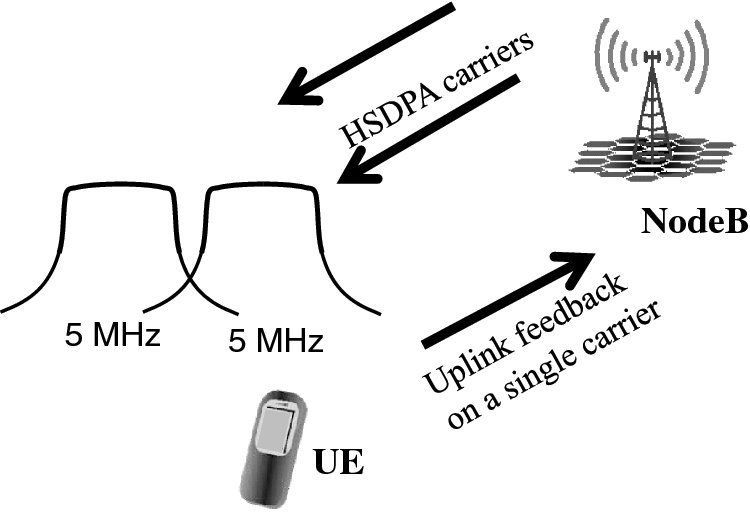
Figure 3.1 Dual-carrier HSDPA principle
From the protocol point of view, the use of dual-carrier HSDPA is only visible to the MAC layer. The data is provided from the RNC Mac-d layer over the Iub to the MAC-hs. The scheduling functionality in the NodeB MAC-hs will then determine, based on the physical layer feedback provided for both downlink carriers (CQI as discussed in Chapter 2), which carrier is better suited for data transmission or if even both should be used simultaneously. Once the data is provided to one of the HS-DSCH transport channels, corresponding to one carrier, then the HARQ procedures are carrier specific, as shown in Figure 3.2.
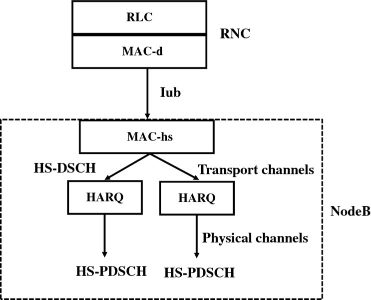
Figure 3.2 Dual-cell HSDPA impact to protocol architecture
The use of two carriers allows benefiting from the frequency domain scheduling by selecting to always use the better carrier from the frequency selective fading and interference point of view. The data rate reached can be twice that of the data rate of a single carrier, with the UEs in the field typically supporting up to 42 Mbps, double the single carrier 21 Mbps data rate when 64QAM modulation is supported.
In the downlink direction, each carrier uses its own HS-SCCH as described in Chapter 2. The UE complexity increase from receiving two carriers was limited by requiring UE to receive at most six HS-SCCHs in total while keeping the limit of a maximum of four HS-SCCHs per cell. In the uplink direction the feedback is organized with HS-PDCCH in such a way that a single HS-PDCCH may carry the necessary ACK/NACK and CQI feedback for two downlink carriers. The multiplexing of the CQI feedback for two downlink carriers on a single uplink HS-PDSCH is shown in Figure 3.3, with the solution being concatenation of two CQI feedbacks and then using (20,10) block code instead of (20,5) code. With the ACK/NACK respectively more code works are used with the 10-bit sequence. The driver for using a single code is to avoid the further increase of peak to average ratio (or cubic metric) of the uplink transmission, which would require reduced uplink transmit power or a bigger and less power-efficient power amplifier.
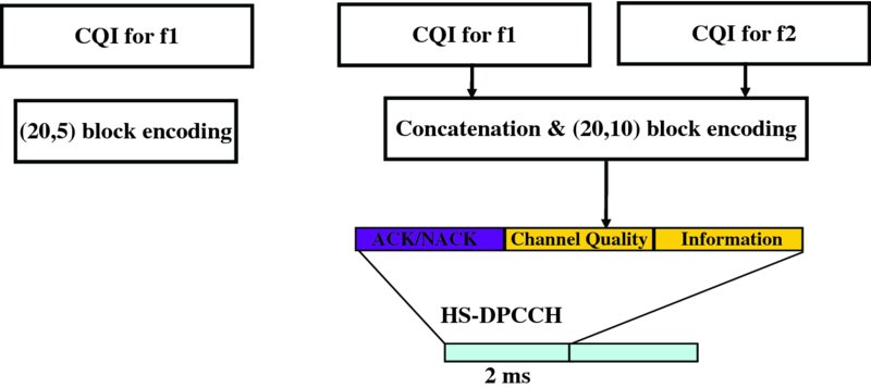
Figure 3.3 Uplink CQI feedback encoding for dual-cell HSDPA
For the dual-cell HSDPA operation new UE capabilities were introduced in [3], as illustrated in Table 3.1 The common UE capability implemented in the field is category 24, which supports two carriers with 21 Mbps each and thus results in a 42 Mbps peak data rate together with 64QAM support and 1/1 coding rate. Release 9 enables combining two-stream MIMO reception to reach 84 Mbps with two-carrier operation.
Table 3.1 Dual-cell HSDPA in Release 8 UE capability
| Cat | Codes | Modulation | Coding | Peak LI data rate (Mbps) |
| 21 | 15 | 16QAM | 5/6 | 23.4 |
| 22 | 15 | 16QAM | 1/1 | 28.0 |
| 23 | 15 | 64QAM | 5/6 | 35.3 |
| 24 | 15 | 64QAM | 1/1 | 42.2 |
For terminal power consumption, it is important to avoid keeping dual-cell reception on when there is not that much data to be transmitted for a given terminal. Besides the RRC reconfiguration, also with the use of physical layer signaling, with HS-SCCH orders can be used to activate and deactivate reception of HSDPA on two carriers, as shown in Figure 3.4, with the secondary carrier deactivation using HS-SCCH orders. The principle of HS-SCCH orders was as introduced in Release 7 with Continuous Packet Connectivity operation, as explained in Chapter 4.
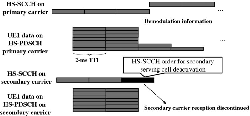
Figure 3.4 Dual-cell HSDPA deactivation with HS-SCCH order
The use of HS-SCCH orders can be used both to activate and deactivate the secondary carrier, thus enabling quick reaction at the NodeB level to the amount and/or priority of data in the NodeB buffer for the UE.
The mobility is based on the primary serving HS-PDSCH cell. In the case of the Release 8 dual carrier the secondary carrier is always adjacent to the primary carrier, thus the path loss is more or less the same to NodeB from both carriers.
3.2.1.1 The Performance of Dual-Cell HSDPA
Release 8 DC-HSDPA doubles the user data rate if the number of users, or the load in general, is low because a single user can utilize two parallel frequencies. When the system load increases, the probability decreases that a single user can get access to the full capacity of both frequencies. Also with very large number of users on both carriers it is more likely that a user has good conditions and can be scheduled using low coding overhead and high order modulation. But even at high load DC-HSDPA provides some capacity benefit compared to two single carriers. The principles of the DC-HSDPA gains are illustrated in Figure 3.5 with the theoretical performance of DC-HSDPA, showing the double data rate at a low load situation and smaller gains at a high load situation. The DC-HSDPA feature is fully backwards compatible as there are no negative impacts with the legacy devices as a legacy UE does not notice any difference in the downlink waveform even if part of the devices operate in the dual cell HSDPA mode.
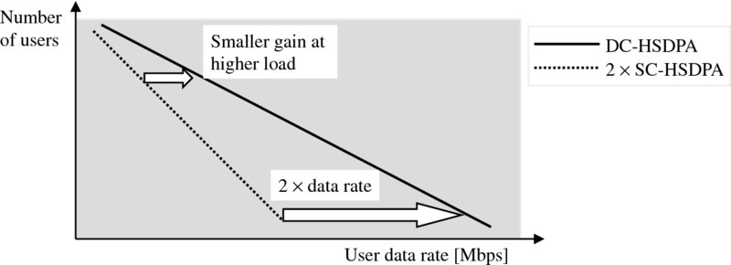
Figure 3.5 DC-HSDPA theoretical performance benefits over single-carrier HSDPA operation
The capacity benefit with DC-HSDPA comes from the following sources:
- Frequency domain scheduling benefit. NodeB scheduler can now dynamically select even every 2 ms the carrier with better link conditions. There is of course only the carrier level granularity of 5 MHz available.
- Load balancing gain, as similarly the NodeB scheduler can also base the selection every 2 ms to select the carrier with less load. This provides benefits for the network as a whole since now the DC-HSDPA capable devices can be scheduled dynamically on either carrier, allowing better service for legacy devices too when compared to the situation with all devices being just single-carrier HSDPA capable.
- Multiuser diversity, as the scheduler has now larger pool of users since DC-HSDPA users are available on both carriers to choose from in the NodeB scheduler.
Figure 3.6 shows the simulated capacity gains with Pedestrian A and Pedestrian B multipath profiles. The results show that DC-HSDPA can improve the cell capacity by 20% compared to two Single-Carrier HSDPA (SC-HSDPA) carriers with ideal load balancing between the carriers. Thus the gain varies from 20% in high load cases to up to 100% gain in low load situations. An important observation from the distribution is that both average capacity and cell edge capacity are improved.
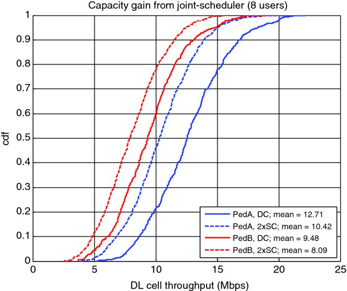
Figure 3.6 DC-HSDPA capacity gain with high load [2]
3.2.1.2 Dual-Band Dual-Cell HSDPA
Release 9 enhanced further the dual-cell HSDPA operation by defining support for the case of having the carriers on different frequency bands. This is typically beneficial when dealing with lower frequency bands such as 900 and 2100 MHz. In this case the 900 MHz band often has room for a single 5 MHz carrier, especially if it is still partly used for GSM. The use of dual-band operation allows one to benefit from the better coverage offered by the 900 MHz band, but also when path loss is small enough to additionally benefit from the increased performance with two carriers without having to hand over to rely only on the 2100 MHz layer HSDPA coverage. The defined band combinations for dual-band dual-carrier HSPA are shown in Table 3.2.
Table 3.2 Dual-band dual-cell HSDPA band combinations in Release 9 and 10
| Band combination | 3GPP Release |
| Band 1 (2100 MHz) and Band 5 (850 MHz) | Release 9 |
| Band 1 (2100 MHz) and Band 8 (900 MHz) | Release 9 |
| Band 2 (1900 MHz) and Band 4 (2100/1700 MHz) | Release 9 |
| Band 1 (2100 MHz) and Band 11 (1450 MHz) | Release 10 |
| Band 2 (1900 MHz) and Band 5 (850 MHz) | Release 10 |
3.2.2 Dual-Cell HSUPA
Dual-cell HSUPA was introduced in Release 9. In dual-cell HSUPA the UE may be assigned one or two uplink carriers from the same NodeB for data transmission. Compared to the downlink multicarrier concept, in the uplink the UE is power limited, which means doubling the bandwidth does not lead to doubling the power.
When a UE is configured into dual-cell HSUPA, a UE is at the same time configured to at least two downlink frequencies corresponding to the two uplink frequencies, that is, the UE is at the same time configured in the downlink as dual-cell HSDPA, four or eight carrier HSDPA.
Dual-cell E-DCH can only be operated with 2-ms TTI. The channels E-DPDCH, E-DPCCH, and DPCCH are sent per activated uplink frequency, while the HS-DPCCH is only transmitted on the primary uplink frequency. In the downlink the F-DPCH, E-HICH, E-RGCH, and the E-AGCH are sent per frequency on the corresponding downlink frequency. An overview of the different channels can be seen in Figure 3.7.

Figure 3.7 Overview of the different channels and frequencies. F1 is the primary uplink frequency
Power control, HARQ, and packet scheduling are performed independently per activated frequency, while also the active sets on both frequencies are independent.
The RNC configures the UE in dual-cell mode, while the NodeB can use HS-SCCH orders to activate and deactivate the Secondary Downlink Frequency and Secondary Uplink Frequency. When the frequency of the Secondary Serving HS-DSCH cell is deactivated using an HS-SCCH order, the associated Secondary Uplink Frequency is also deactivated, while the deactivation of the Secondary Uplink Frequency using an HS-SCCH order does not imply the deactivation of the Secondary Downlink Frequency. When the UE hits its maximum transmit power, the UE reduces the power used on the data channel (E-DPDCH) on the carrier with the highest DPCCH power, that is, on the carrier with the worst radio conditions.
Figure 3.8 shows the performance of DC-HSUPA and a single-carrier HSUPA network with the same load per carrier with an Inter Site Distance (ISD) of 500 meters and target Raise Over Thermal (Rot), that is, uplink interference level, increase of 6 dB. It can be seen that at low loads the throughput is doubled for UEs, whereas the gain decreases with the load. The gain also depends on the coverage. This can be seen by comparing Figure 3.8 and 3.9 where the ISD is increased from 500 to 1732 m. The gain in user throughput at low load has now decreased to 50%, while it decreases to lower numbers when the load increases. This is caused by UEs more likely being power limited and therefore unable to turn the extra carrier into extra throughput. Therefore the use of DC-HSUPA is especially beneficial in small cells or in large cells close to the base station.
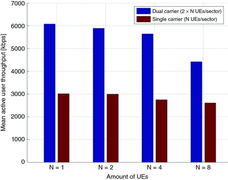
Figure 3.8 Mean active user throughput for N = [1,2,4,8] UEs/sector, ISD = 500, channel profile = PA3 and RoT target = 6.0 dB
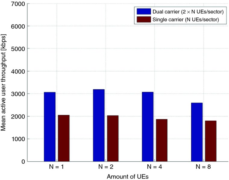
Figure 3.9 Mean active user throughput for N = [1,2,4,8] UEs/sector, ISD = 1732, channel profile = PA3 and RoT target = 6.0 dB
3.3 Four-Carrier HSDPA and Beyond
In later releases the work has continued to define support, first up to four carriers and later even up to eight carriers. Release 10 contains the support for four-carrier HSDPA, which enables the NodeB scheduler to select dynamically from four different 5-MHz carriers, thus covering a total of 20 MHz of bandwidth. In many cases this is not possible for a single operator within one frequency band only, thus dual-band operation is also specified, as illustrated with the example band combination in Figure 3.10. In the case of 4C-HSDPA, the UE provides CQI feedback over four carriers and thus the scheduler can select any of the carriers, effectively using the same RF bandwidth that is used with the LTE 20 MHz carrier case. This enables the re-use of wideband RF UE components designed originally for LTE. Similarly, on the network side the activation of two or more carriers is rather simple, especially if the site already uses more than a single HSDPA carrier. The market utilization of more than two HSDPA carriers remains to be seen as currently the only dual-cell that is supported widely in the latest devices in the marketplace. It is also possible to implement the three-carrier case, which in many instances fits to a single frequency band only, such as the examples with the 2100 MHz (band 1) case.
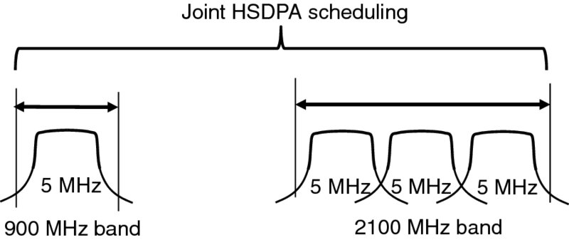
Figure 3.10 4C-HSDPA scheduling principle
The performance of four-carrier HSDPA offers 4 times the peak data rate in the low loaded case compared to the single HSDPA carrier case as can be seen in Figure 3.11. The frequency domain scheduling benefit is not quite as high as with the LTE since the granularity with - MHz blocks is clearly bigger than the 180 kHz granularity possible with LTE, as addressed in [4]. Similar to the dual-cell case covered earlier, the capacity benefit is reduced when the load increases. The peak data rate without MIMO is 4 times 21 Mbps, thus reaching 84 Mbps, with 2 × 2 MIMO up to 168 Mbps.
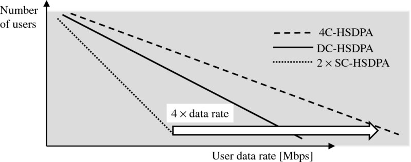
Figure 3.11 Performance of 4C-HSDPA over single-carrier HSDPA as a function of number of users
Release 11 has defined further support for up to eight-carrier HSDPA, enabling a peak data rate of up to 168 Mbps without MIMO and up to 334 Mbps with 2 × 2 MIMO and even 668 Mbps with 4 × 4 MIMO, which was also added in Release 11.
The benefits of aggregating multiple carriers are significant for the end user, since often free resources are available in the other carriers. This can be seen in Figures 3.12 and 3.13, which show the cdf of the average user throughput and the mean packet throughput at low loads.
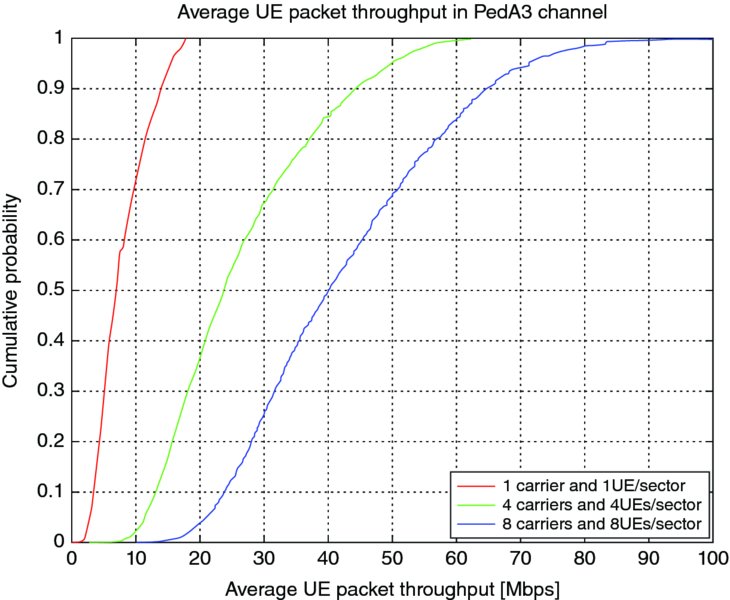
Figure 3.12 Cumulative distribution of the average UE packet throughput (Mbps) for one, four, and eight carriers at low load
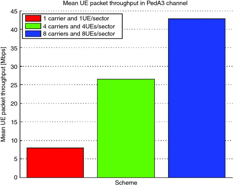
Figure 3.13 Mean UE packet throughput (Mbps) for one, four, and eight carriers at low load
Similar to the dual-cell HSDPA, as with more than two carriers the achievable gains depend a lot on the load in the system. If the load is high, then there will be fewer free resources on the other carriers as well as the fact that scheduler is likely to find users in good channel conditions regardless of the UEs with multicarrier capability, which results in lower gains. This is illustrated in Figure 3.14, which shows the mean packet call throughput as a function of the offered load per carrier.

Figure 3.14 Mean UE packet throughput (Mbps) for one, four, and eight carriers as a function of the load
3.4 Multiband HSDPA
As was already addressed with Release 9 dual-band dual-cell HSDPA, 3GPP specifications enable the use of two frequency bands simultaneously when using more than a single HSDPA carrier for a given UE, in a similar fashion to that enabled by the LTE-Advanced using inter-band carrier aggregation (CA). All the band combinations are UE capabilities and a UE may end up supporting only a single band combination, or then supporting only single band operation. A band combination may be added in 3GPP as a Release independent case, similar to a frequency variant. This means that when adding a new band combination, for example in Release 12, only necessary RF requirements need to be supported, but otherwise the Release where the necessary number of carriers was defined in the first place only needs to be followed. This is similar to the LTE CA band combination principle as covered in [5].
The band combinations so far defined in 3GPP in addition to the dual-carrier cases covered in Table 3.2 are listed in Table 3.3, together with their corresponding Release. In all cases the uplink can be on either of the bands.
Table 3.3 4/8-carrier HSDPA band combinations defined in 3GPP
| Bands | Release |
| Band 1 (2100 MHz) and Band 8 (900 MHz) | Release 10 |
| Band 1 (2100 MHz) and Band 5 (850 MHz) | Release 10 |
| Band 2 (1900 MHz) and Band 4 (2100/1700 MHz) | Release 10 |
| Band 2 (1900 MHz) and Band 5 (850 MHz) | Release 11 |
3.5 Downlink MIMO
Multiple transmit and receive antennas open the possibility of exploring the spatial dimension. In the following, different mechanisms for exploration are briefly summarized and then their implementation in HSPA is detailed.
Space-time coding, or Space-Time Transmit Diversity (STTD) in 3GPP, is an open-loop diversity scheme which uses a constant coding scheme. Many different space-time codes are described in literature, for example, space-time trellis codes, differential space-time codes, or space-time block codes. From a decoding perspective, orthogonal space-time block codes show very low complexity. The Alamouti code [6] was proven to be the only orthogonal space-time block code which provides full diversity and was included already in Release 5 of the HSPA standard.
An alternative group of MIMO schemes rely on feedback and are called closed-loop spatial multiplexing. Within the closed-loop transmit diversity schemes, two different gain mechanisms are used, that is, array gain and multiplexing gain.
Array gain is sometimes called beamforming gain which may be misleading since no literal beams are created. The schemes standardized in 3GPP for HSPA are rather adaptive spatial filters (pre-coders) which allow for a coherent superposition of the received signal from different transmit antennas based on the feedback of the receiver. The spatial filter adapts to the fading channel over time and does not create a fixed beam towards a certain direction. Due to the coherent superposition, the received signal power is increased which is particularly useful under high interference at the cell edge.
Spatial multiplexing increases the number of streams transmitted in parallel over multiple antennas. The main challenge of the multiplexing scheme is the decoding, since all streams have to be separated. Therefore, at least as many receive antennas are required as streams are multiplexed and orthogonal pre-coding is used. Multiplexing multiple streams distribute the overall transmit power equally between the streams and the power per stream is lower. Hence, the decoding of multiplexed streams require good to very good channel conditions which are typically found in the cell center.
With spatial filtering (beamforming) providing gains at the cell edge and spatial multiplexing in the cell center, the combination of both is natural. However, there is a natural tradeoff between array gain and multiplexing gain [7]; for example, transmitting the maximum number of stream (= number of transmit antennas) leaves no array gains and when capturing the maximal array gain only one stream can be transmitted.
3.5.1 Space Time Transmit Diversity – STTD
STTD is an open-loop transmit diversity scheme and corresponds to the Alamouti code. Figure 3.15 illustrates how the bit mapping scheme defined in [8] can be translated to the Alamouti scheme by considering how the bits are mapped to complex symbols (here for simplicity QPSK).
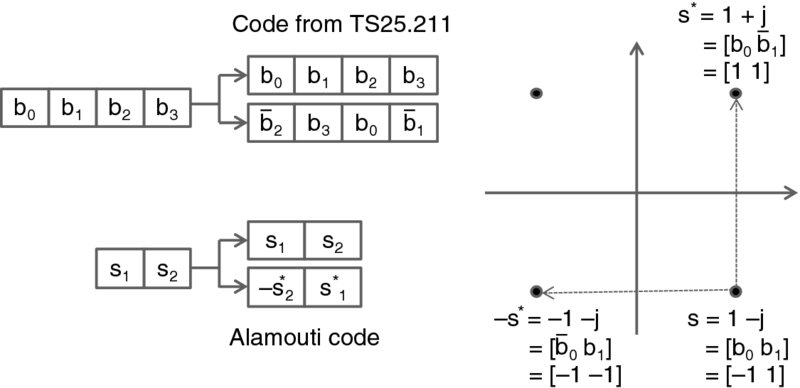
Figure 3.15 Mapping of 3GPP STTD scheme to the Alamouti code for QPSK where s* is the conjugate of s and b = −b
STTD requires only one receive antenna and no additional feedback information has to be provided by NodeB. This coding scheme can be applied to all physical downlink channels and is made mandatory for the UE.
However, STTD has some technical shortcomings. First, it does not support Continuous Packet Connectivity (CPC), with CPC details as covered in Chapter 4. Second, STTD makes the channel of one symbol appear longer since it is spread over two slots. The equalizer at the UE has now to estimate the multipath components of two channels spread over two symbols. This makes the implementation of the RAKE receiver in the UE much more complex when keeping the equalization performance constant. This means that STTD is not deployed in practical systems.
3.5.2 Closed-Loop Mode 1 Transmit Diversity
Two closed-loop modes were defined in Release 99, mode 1 and mode 2. Mode 2 was later removed from Release 5 onwards because it was never implemented in the networks. In mode 1, the UE provides the NodeB with a phase offset between the first and the second transmit antenna. The phase offset is transmitted as Feedback Information (FBI) over two consecutive TTIs. Since FBI contains only 1 bit, four different phase offsets can be signaled to the NodeB. Closed-loop transmit diversity mode 1 can be applied to PDCH and HS-PDSCH. In practice, mode 1 does not support continuous packet connectivity (CPC).
3.5.3 2 × 2 MIMO and TxAA
With Release 7 MIMO was introduced to HSDPA. The closed-loop scheme is based on feedback of the pre-coding index which defines the weights used in the spatial pre-coder. Figure 3.16 shows the pre-coding and the superposition of additional channels. As shown, MIMO can only be used for HS-DSCH. All control channels and HS-DSCH for non-MIMO do not use the MIMO pre-coder and are shown as other channels in Figure 3.16.

Figure 3.16 MIMO pre-coding of HS-DSCH channels
As shown in the right part of Figure 3.16, pre-coding is a weighted distribution of HS-DSCH to the two transmit antennas. The pre-coding weights can be combined into a pre-coding matrix Wn, with
as defined in Figure 3.16 and the pre-coding index n. Beside the preferred pre-coding matrix, the UE also indicates the preferred rank of the transmission, that is, how many streams would be optimal to transmit from a UE perspective. In single-stream transmission, only HS-DSCH1 is present which benefits from array gains. Typically, single-stream transmission is used towards the cell edge. In dual-stream transmission, both streams are present and share the total transmit power. Considering further that multipath channels introduce additional interference between the two streams, much better reception conditions are required to decode dual-stream MIMO. Hence it is mainly used towards the cell center.
Doubling the number of HS-DSCH enables a double peak data rate in downlink but also increases the feedback required in uplink. Both the hybrid-ARQ acknowledgement (HARQ-ACK) and the Channel Quality Indicator (CQI) have to be transmitted for both streams. In addition the Precoding Control Indicator (PCI) and the Rank Indicator (RI) have to be transmitted in uplink. Hence the coding of the HS-DPCCH was updated for MIMO.
Figure 3.17 shows the frame structure of the HS-DPCCH which consists of three slots, one for HARQ-ACK and two for CQI and PCI. To accommodate the additional HARQ-ACK in the first slot (10-bit), new coding with decreased Hamming distance between the code words was introduced.
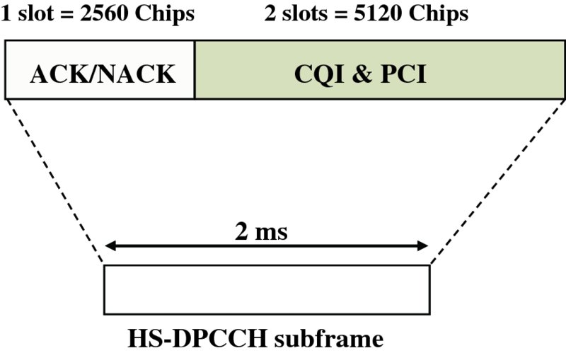
Figure 3.17 HS-DPCCH structure
For the channel quality reporting, two types of CQI report were introduced: type A and type B. The type A report is periodically sent by the UE and may contain a single 5-bit CQI value if single-stream transmission is preferred or two CQI values if dual-stream transmission is preferred. The report is 8 bit which results in 256 CQI values. The first 31 values (5 bits) are used to indicate single-stream CQI values. The remaining 225 values are used for dual-stream CQI1 and CQI2, where the combined CQI value is given as CQI = 15×CQI1 + CQI2 + 31. Note that the rank indicator is implicitly signaled by the number of preferred streams. A type B report is a 5-bit single-stream CQI report. The UE can be configured such that the report is transmitted periodically to create a reliable single-stream reference for the scheduler.
Two PCI bits are simply prepended to the 8|5 bits of the CQI report. The resulting 10|7 bits are coded by a (20,10) | (20,7) code and transmitted during the remaining two slots of the HS-DPCCH.
Figure 3.18a shows the original version of MIMO that includes the primary CPICH (P-CPICH) being transmitted in STTD mode. As mentioned earlier, STTD may have reduced performance due to channel estimation. Also, in the original MIMO scheme all non-MIMO, non-STTD signals are transmitted from antenna 1, which leads to a power difference between the two antennas. This implies that some fraction of available transmit power is not used at transmit antenna 2. The use of original MIO caused clear performance degradation with the existing devices in the field. The interference from the additional pilot caused problems for the single antenna equalizer devices and thus would cause the actual network capacity to go down if the MIMO were used in a commercial network with legacy devices.
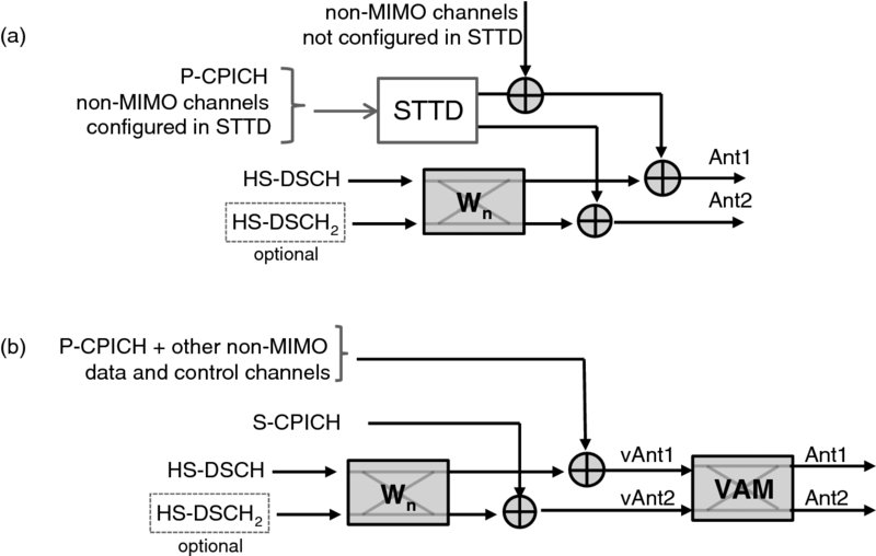
Figure 3.18 Block diagram of original Release 7 MIMO and the work-around solution
To avoid those issues, a work-around MIMO solution was standardized. The solution is shown in Figure 3.18b. Instead of using the P-CPICH transmitted in STTD mode, two different pilot signals are used where the primary CPICH is transmitted over antenna 1 and a secondary CPICH (S-CPICH) from antenna 2. This simplifies channel estimation and equalization.
To overcome the imbalanced power issue, a power balancing network can be assumed which maps the signal of the virtual antennas (vAnt1 and vAnt2) to the physical antennas (Ant1 and Ant2). This Virtual Antenna Mapping (VAM) network is not standardized and transparent for UE. The VAM appears to the UE as part of the channel since all pilot signals are also transmitted over the VAM. Depending on the used VAM matrix, the power of the first stream is not mapped equally to both transmit antennas. In the extreme case, all the power of stream 1 is mapped to one transmit antenna for two pre-coding matrices. For the other two pre-coding matrixes the power is balanced. In order to enable balanced transmit power also for single-stream transmission, this extreme case is used with the set of pre-coding weights limited to a size of 2. This reduces the performance slightly but allows for balanced output power. To enable this, the NodeB can inform the UE on how many weight sets to use. Those work-around solutions were included in Release 7 in 2012 as a late inclusion.
While Release 7 MIMO requires two receive antennas, a new transmit diversity scheme called TxAA was introduced in Release 9, which operates also with a single receive antenna in the UE. TxAA functionality is equivalent to single-stream MIMO.
3.5.4 4-Branch MIMO
Downlink 4-branch MIMO was standardized in Release 11 as a straightforward extension to 2 × 2 MIMO. The NodeB can transmit up to four parallel streams (branches) which doubles the peak data rate per carrier. However, 4-branch MIMO only supports up to four carriers and hence the HSDPA peak data rate remains at 336 Mbit/s. Since a UE supporting 4-branch MIMO is assumed to have advanced receiver, the UE has to have the capability of decoding at least two streams (two Rx antennas) and has to support at least two carriers.
In practice it is expected that there will be more terminals with two receive antennas. Four antennas will be only realistic in larger devices like tablets or laptops. Hence, the 4-branch MIMO design focuses more on optimizing 4 × 2 transmissions and enabling 4 × 4 MIMO. The main limitation of transmitting up to four streams is to feedback CQI and HARQ ACK/NACK on the uplink HS-DPCCH especially since this channel also has to carry an extended pre-coding index and rank index.
To limit the feedback in uplink, up to two transport blocks are bundled in codewords and the CQI/HARQ ACK/NACK is transmitted only per codeword. This allows for transmitting four transport blocks with the same amount of feedback as would be required for two transport blocks. The transport block bundling causes some limited performance loss since the whole codeword has to be retransmitted when the transmission of only one transport block fails. Also the feedback of combined CQI values implies that for both transport blocks the same modulation and coding is used even though they are transmitted over different layers which may have different quality. To obtain an equal performance for both transport blocks in one codeword, the transport blocks are interleaved within the codeword. If one or two transport blocks are transmitted in parallel, each transport block is mapped to one codeword and no performance reduction is observed. The codeword mapping is illustrated in Figure 3.19.
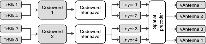
Figure 3.19 Transport block to codeword mapping introduced to 4-branch MIMO to reduce feedback
4-branch MIMO uses the same codebook for spatial pre-coding as LTE. The codebook has 16 sets of pre-coding weights where the optimal set is chosen by the UE. The NodeB is informed which set to use by the 4-bit pre-coding indicator (PCI). Figure 3.20 shows how 4-branch MIMO channels are combined with 2 × 2 MIMO, non-MIMO, and signaling channels. For legacy reasons, non-MIMO HS-DSCH and other signaling channels have to be transmitted together with the primary pilot (P-CPICH) over the first (virtual) antenna. The same applies for the first secondary pilot (S-CPICH1) and output of the 2 × 2 MIMO pre-coder Wn.
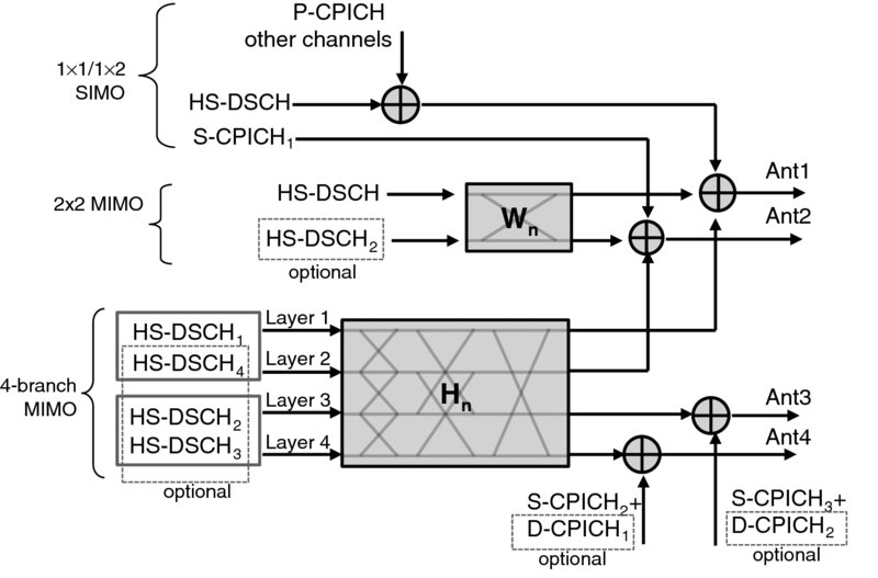
Figure 3.20 4-branch MIMO block diagram with newly introduced pilot channels and the combination with 2 × 2 MIMO and non-MIMO
The 4-branch MIMO pre-coder Hn can multiplex one to four layers (streams). If only one layer is transmitted, HS-DSCH can't be combined with a not-present channel to one codeword and is transmitted only over layer 1. The same applies for HS-DSCH2.
The changes to HS-DPCCH are limited thanks to the introduction of codewords. The HARQ-ACK feedback the CQI reports remain unchanged. Only the pre-coding indicator is extended from 2 to 4 bits and 2 bits are added to indicate that the Number of Transport Blocks Preferred (NTBP) are introduced which corresponds to the rank indicator in LTE. Those four new bits can be accommodated in the HS-DPCCH by using a rate 1/2 convolutional code for type A reports and rate 1/3 convolutional code for type B reports. Note that the increased error probability due to reduced coding protection has to be compensated by higher transmit power.
Since the channel between each transmit antenna and receive antenna has to be estimated separately, new pilot signals have to be introduced. Adding more pilots with similar power as the P-CPICH would imply for four transmit antennas that 40% of the total power is used for pilot signals, which is clearly too much. Hence a different solution is used.
The common and secondary pilots are required for
- channel quality measurement and
- channel estimation for demodulation.
While the channel quality measurement needs to be done every TTI to calculate the channel quality indicator (CQI), the channel estimation for demodulation is only needed when a data channel is scheduled in downlink. Pilots for channel quality measurements require much less power since the accuracy of the channel estimate needs to be much lower. The channel estimation for decoding directly influences the decoding and system performance.
According to the two different requirements, two different pilot signals are introduced for 4-branch MIMO. New secondary CPICH channels are transmitted permanently over antenna 3 and 4. The power of the newly introduced pilot channels is defined relative to P-CPICH and can vary from −12 to 0 dB (see Figure 3.21). The secondary pilot 2 and 3 are used to calculate periodical CQI reports. In many cases the power of S-CPICH2/3 is also sufficient for decoding. High pilot power similar to P-CPICH is only required for UEs at the cell edge with unfavorable channel conditions. For this worst case UEs, two additional demodulation common pilot channels (D-CPICH) can be scheduled.
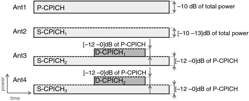
Figure 3.21 Power level of additionally introduced pilot channels for antenna 3 and 4 (D-CPICH – demodulation-CPICH)
Similar to S-CPICH2/3, the power of D-CPICH1/2 is defined by higher layers between 0 and −12 dB according to the cell size, for example. The UE is informed about the additionally scheduled D-CPICH via HS-SCCH order.
Figure 3.22 shows expected gains obtained from 3GPP conform system-level simulations with conservative pilot power settings and dynamic rank switching. In the figure all combinations of receive and transmit antennas are compared where the case of 4Tx MIMO with one receive antenna is not standardized but is given here for completeness. It can be observed that 4-branch MIMO brings clear gains with respect to 2Tx MIMO ranging from 8.5% for one receive antenna to 22% for four receive antennas.
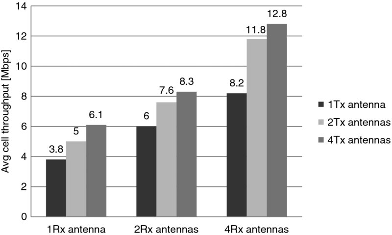
Figure 3.22 Gains for different constellations of receive and transmit antennas. Note that the 4 × 1 case is not standardized and is shown only for reference
3.6 Uplink MIMO and Uplink Closed-Loop Transmit Diversity
Following the IMT-Advanced requirements for the peak data rate was the main motivation behind the standardization of uplink MIMO (and 64QAM) in Release 11. After downlink MIMO was standardized in Release 7 it was an obvious step forward to pursue similar multiple antenna benefits in uplink too. Compared to uplink 16QAM single antenna transmission the introduction of uplink MIMO will allow increasing peak, average, and cell edge spectral efficiencies. Secondary pilot and control information on the second stream must be transmitted in order to support uplink MIMO features. Thus the pilot power overhead must be taken into consideration [9].
Similar to downlink, both Closed-Loop Transmit Diversity (CLTD) and MIMO modes were introduced in uplink. In CLTD mode the serving cell provides a UE with feedback on the phase offset between the signals from the two transmit antennas. The corresponding phase delay is then applied by the UE to the uplink data channels in order to achieve a coherent superposition of the received signal at the Base Station, which results in higher received power. Uplink MIMO allows transmission of up to two Transport Blocks on two spatial streams – this is called MIMO Rank-2. The pre-coding principle is the same as in the downlink case described in Section 3.5. MIMO Rank-1 is a transmission scheme which works technically in the same way as CLTD with a difference that CLTD is a separate feature from the standard perspective. Thus, it can be used by UEs which do not support MIMO. On the other hand, MIMO-enabled UEs utilize the benefits of both Rank-1 and Rank-2 modes and the rank selection is performed dynamically depending on the channel conditions. What differentiates uplink multiple antenna techniques from the similar approaches introduced in downlink is the possibility of switching the transmit antennas. The antenna switching mode allows the UE to use only one of the two available transmit antennas based on which one provides better received signal power. This is especially beneficial in a scenario where there is a substantial imbalance in the signal levels received from those antennas because one of the antennas suffers from strong shielding.
Both CLTD and MIMO are enabled by the HS-SCCH orders from the serving cell. What is also common is the Pre-Coding Indicator (PCI) feedback, which in both cases is carried on an F-DPCH-like channel, F-TPICH.
Figure 3.23 depicts the new uplink channels introduced for uplink CLTD and uplink MIMO. The CLTD requires additional pilot channel S-DCCH which is sent from the second antenna. In the case of uplink MMO Rank-2 two additional channels are transmitted that is, S-E-DPDCH carrying the secondary TB and S-E-DPCCH carrying control data corresponding to the additional stream.
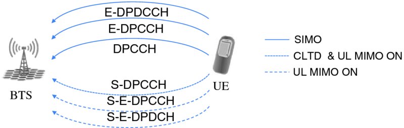
Figure 3.23 Overview of the different channels in case of SIMO, UL CLTD, and UL MIMO
During the uplink MIMO Rank-2 studies it was decided to transmit dual TB independently over the spatial streams. It was also decided that each spatial stream use independent E-TFC selection (rate adaptation). This operation provides more flexibility and maximizes the achievable throughput. The drawback of this solution is the additional overhead of the scheduling and HARQ control information which is associated to each stream in uplink. In downlink for each stream the E-TFC indicator (E-TFCI) and the ACK/NACK must be sent. The two transport blocks are acknowledged independently using the E-HICH channel, where two different signatures are configured on the same E-HICH code channel. There is only one inner and outer power control loop for both streams.
However it was not the only scheme that was evaluated during the Rel-11 studies. Two others had some benefits and drawbacks compared to the chosen one but based on the performance results were not selected. Nevertheless, in order to give some background short descriptions are provided below [10]:
- Design #1 – single Transport Block Rank-2 transmission. Due to the fact that in this case it is sufficient to indicate a single E-TFC and transmission rank in uplink, there is low control signaling overhead. The main disadvantage of this approach is the low channel adaptation ability, in a situation where there is strong imbalance between MIMO spatial streams, due to the fact that all parameters for both spatial streams should be the same, that is, modulation, OVSF code allocation, bit mapping and power allocation.
- Design #2 – dual TB Rank-2 transmission, TBs interleaved between the two spatial channels. This option can be described as a hybrid between design #1 and the standardized design which was described in the paragraph above. Interleaving allows transmission of each TB over the same channel conditions. In terms of signaling, the HARQ overhead is the same as in the standardized solution. It was discarded because, similarly to design #1, this approach facilitates less efficient scheduling.
It is worth noting that if the transmission of the TB on the secondary stream fails for whatever reason, uplink MIMO Rank-2 mode will be operated as it was uplink CLTD (or uplink MIMO Rank-1). More details about differences between uplink MIMO and beamforming CLTD are presented in the figures in Section 3.6.1 below.
3.6.1 Uplink MIMO Channel Architecture
In order to benefit from uplink MIMO transmission there is a need to introduce new uplink physical channels that is, Secondary Dedicated Physical Control Channel (S-DPCCH), Secondary Dedicated Physical Control Channel for E-DCH (S-E-DPCCH) and Secondary Dedicated Physical Data Channel for E-DCH (S-E-DPDCH) as they are shown in the Figure 3.24 below.
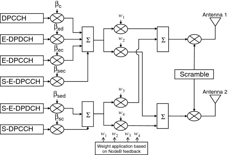
Figure 3.24 Channel configuration in case of UL MIMO Rank-2 transmission
Details about channel configuration of UL CLTD are presented below in Figure 3.25.
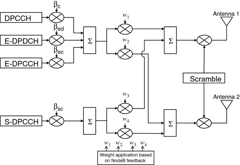
Figure 3.25 Channel configuration in case of uplink MIMO Rank-1 transmission that is, uplink CLTD
As presented in the figures below, a UE is able to transmit data in an additional two instances (depending on network conditions and UE capability):
- UL-CLTD (Uplink MIMO Rank-1) – DPCCH, E-DPDCH, E-DPCCH and S-DPCCH
- Uplink MIMO (Rank-2) – DPCCH, E-DPDCH, E-DPCCH, S-DPCCH, S-E-DPCCH and S-E-DPDCH.
It is worth noting that all control and data channels use the same pre-coding vector ([w1 w2]) as DPCCH, only secondary DPCCH and the secondary E-DPDCH use orthogonal pre-coding vector ([w3 w4]).
S-DPCCH has a mandatory role in both uplink MIMO transmission modes. In Rank-1, that is, uplink CLTD, it was introduced for channel sounding of the secondary stream. By this we are able to choose the optimal pre-coding vector which will be used for future transmissions. It can also be supportive for data demodulation.
In the case of uplink MIMO Rank-2 it is used not only for the best pre-coder selection but also as a phase reference for data demodulation on the secondary stream.
An additional two channels are needed in the case of uplink MIMO Rank-2 transmission. The S-E-DPCCH channel is responsible for carrying E-TFCI and the Retransmission Sequence Number (RSN) for the secondary data stream and S-E-DPDCH channels are used to carry transport blocks on the secondary stream.
3.6.2 Scheduling and Rank Selection with Uplink MIMO
The agreed MIMO architecture includes transmission of two (for Rank-2) or one (for Rank-1) TB(s) independently over the two spatial channels. A scheduling and rank-selection algorithm has to simultaneously select the transmission rank and either two (for Rank-2) or one (Rank-1) E-TFCs (or equivalent transmission grants). The traditional scheduling procedure is applied to the primary spatial stream and the E-TFC is selected based on the transmission grant provided by the NodeB that is, the serving grant. The secondary stream uses the virtual serving grant. Grant for the second stream is calculated based on the combination of transmit power which is chosen for the primary stream and offset value which is provided by the NodeB over the E-DCH Rank and Offset Channel (E-ROCH) together with rank indication. When calculating E-TFC for the secondary stream based on the virtual SG the same legacy gain factor tables are used [11,12].
The block-diagram of the power-based scheduling and rank selection algorithm is provided in Figure 3.26.

Figure 3.26 Block diagram of power-based scheduling and rank selection algorithm for HSUPA MIMO
According to the block diagram, retransmissions are considered first and, if they happen, are done in compliance with the used MIMO H-ARQ protocol. When no retransmissions are expected, the scheduling is performed independently for Rank-1 and Rank-2 transmissions and the rank providing the maximum throughput is selected.
The Rank-1 scheduling and the primary spatial channel scheduling for Rank-2 use the legacy scheduling procedure as for the SIMO. This is possible because of the MIMO transmit power control implementation where one Inner-Loop Power Control (ILPC) and one Open-loop Power Control (OLPC) operate over the primary spatial stream. The E-TFC to be sent over the primary spatial channel for both Rank-1 and Rank-2 is selected to provide the maximum throughput and for the total predicted received power to be below the available received power budget.
For the secondary stream of a Rank-2 transmission, the scheduling approach is different and the following principles are applied:
- Transmit power used for the secondary stream is equal to the power of the primary stream.
- No independent fast power control ILPC/OLPC is applied for the secondary stream (one ILPC and OLPC for both streams).
- Data rate adaptation is used for secondary stream meaning that the E-TFC is selected based on the post-receiver SINR of the secondary stream to provide the needed BLER performance.
The used procedure actually decouples data rate control and the transmit power control for the secondary spatial stream (that are coupled in SIMO, Rank-1 HSUPA, and Rank-2 primary stream scheduling).
3.6.3 Uplink MIMO Performance Evaluation
This section presents the estimated gains coming from the uplink multiple antenna schemes obtained in the 3GPP link and system level simulations. For the sake of simplicity the results are presented only for the Pedestrian A 3km/h channel model [13] and 2 × 2 antenna configuration. The conclusions drawn from the presented evaluation are valid also for other channel models with minor differences in the absolute numbers.
As can be observed from the simulation results in Figure 3.27, the uplink MIMO scheme, as defined in Release 11, was found to have the best performance for high SINR values, which was to be expected. The apparent lack of CLTD gains comes from the fact that this mode provides benefits in a form of lower UE transmit power and what follows – less interference. This does not manifest in the link level results presented in Figure 3.27 but is responsible for the better CLTD performance in the system-level simulations shown in Figure 3.28.
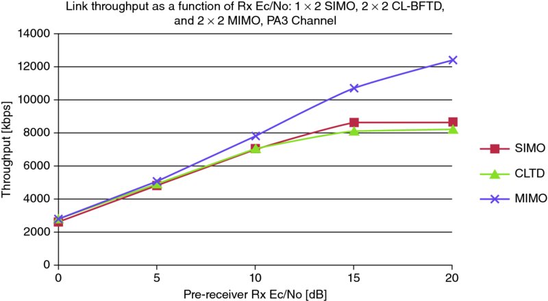
Figure 3.27 Link throughputs of different transmission modes, PedA 3 km/h, 2 × 2 (1 × 2) antenna configuration
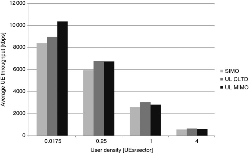
Figure 3.28 System level throughputs for different transmission modes, PedA 3 km/h, 2 × 2 (1 × 2) antenna configuration
The system-level evaluation presented below assumes adaptive rank adaptation in the case of MIMO mode. As mentioned before, the Rank-2 transmission is beneficial only for the very high SINR conditions. That is why the system level gains are observed only for very low UE densities. In other scenarios, the overhead of additional control channels takes away the marginal gains of spatial multiplexing. The benefit of the CLTD method comes from its ability to reach the same throughput by using less transmit power, therefore causing less interference to other UEs. This is why this scheme seems to be beneficial for all user densities. It should be noted that the above evaluation assumes using an inter-stream interference cancellation receiver in case of MIMO. The capability of cancelling the interference from the primary stream was proven to be of high importance for UL MIMO feasibility.
3.7 Conclusions
After the basic HSPA functionality created in Release 5 and 6, HSPA evolution has added a lot of capabilities in both the multiantenna and also the multicarrier domain. While many of the other features in this chapter are still waiting for large scale implementation, the support for dual-cell HSDPA has been already widely deployed globally, and offers the 42 Mbps peak data rate quite commonly. Globally, from all HSPA networks, roughly 1 out of 4 of HSPA networks will have enabled dual-carrier HSDPA by the end of 2013. The chips sets supporting dual-cell HSUPA have been also published, and are expected to be available during 2014 in the marketplace, enabling uplink support of 11.5 Mbps. HSDPA MIMO has been deployed in some networks but was not widely rolled out due to the legacy UE issues as covered in Section 3.5.3. Combining downlink MIMO with dual-cell HSDPA would enable pushing the data rates to 84 Mbps, doubling the currently achievable HSPA peak data rate in the market by many handsets today. Similarly, the HSUPA MIMO has not attracted huge interest in the market due to the highly limited use case with virtually no interfering users in a cell. Uplink closed-loop transmit diversity seems to have more potential in this respect. The 3GPP Release 11 specifications define the necessary support to go beyond the 100 Mbps limit with HSPA too, assuming large enough spectrum availability. On the uplink side, the combination of uplink 16QAM together with dual-cell HSUPA allows data rates of up to 22 Mbps to be reached.
References
- Holma, H. and Toskala, A. (2010) WCDMA for UMTS, 5th edn, John Wiley & Sons, Ltd, Chichester.
- Morais de Andrade, D., Klein, A., Holma, H. et al. (2009) Performance Evaluation on Dual-Cell HSDPA Operation. IEEE Vehicular Technology Conference Fall 2009, Anchorage, Alaska, 2009.
- 3GPP Technical Specification, TS 25.306, “UE Radio Access capabilities”, v 8.12.0, Release 8, June 2012.
- Holma, H. and Toskala, A. (2011) LTE for UMTS, 2nd edn, John Wiley & Sons, Ltd, Chichester.
- Holma, H. and Toskala, A. (2012) LTE-Advanced, John Wiley & Sons, Ltd, Chichester.
- Alamouti, S.M. (1998) A simple transmit diversity technique for wireless communications. IEEE Journal on Selected Areas in Communications, 16(8), 1451–1458.
- Zheng, L. and Tse, D.N.C. (2003) Diversity and multiplexing: a fundamental tradeoff in multiple-antenna channels. IEEE Transactions on Information Theory, 49(5), 1073–1096.
- 3GPP Technical Specification, TS25.211, “Physical channels and mapping of transport channels onto physical channels”.
- 3GPP Technical Report, TR 25.871 v.1.0.1, Release 11, May 2011.
- 3GPP Technical Report, TR 25.871 v11.0.0, Release 11, September 2011.
- 3GPP Technical Specification, TS 25.321, “Enhanced uplink; Overall description Stage 2”, Release 11.
- 3GPP Technical Document, R1-121733 Scheduling and Rank Selection for HSUPA MIMO, RAN1 #68bis.
- 3GPP Technical Document, R1-112632 UL MIMO Link Level Evaluation, Nokia Siemens Networks, RAN1 #66.