
8
Advanced UE and BTS Algorithms
Antti Toskala and Hisashi Onozawa
8.1 Introduction
This chapter presents an overview of recent developments of the advanced UE as well as of advanced BTS algorithms. First the different UE receiver versions are introduced based on the work done in different 3GPP Releases for defining advanced UE performance requirements. This chapter then continues with the introduction of the different scheduling solutions in BTS and then continues to cover BTS interference cancellation. This chapter is concluded with the outlook for looking at other aspects of the UE and BTS algorithms, including the latest development of Network Assisted Interference Cancellation (NAIC) being investigated in 3GPP for Release 12.
8.2 Advanced UE Receivers
The first UE implementations on Release 99 were single receiver solutions based on the traditional Rake receiver, as introduced in [1]. Work then followed to cover the following types of receivers:
- Type 1 receiver in Release 6, which introduced two-antenna receiver diversity in the UE receiver, which became a typical solution especially in data centric products such as USB dongles and ExpressCards. The practical challenges related to design include achieving a low enough correlation between the antennas, especially with the lower frequency bands below 1 GHz. The small size of a device such as a USB dongle adds to the design challenge. Figure 8.1 shows an example performance impact of the antenna correction effect as introduced in [2], illustrating that with higher frequency bands the performance benefit from RX diversity is higher than with the lower frequency bands.
- Type 2 with equalizer, also part of Release 6, introduced an equalizer to tackle the intra-cell interference caused by the multipath channel. With better tolerance of effects of the multipath channel, the usability of higher order modulation, in the case of HSDPA 16QAM and 64QAM, is also improved. Compared to a single antenna Rake receiver the capacity improvement is in the order of 30% [1]. The Type 2 receiver was the typical receiver for smartphone platforms that mainly had only a single antenna. The 3GPP reference equalizer was a Minimum Mean Square Error (MMSE) type equalizer, but such an equalizer was only used to generate the performance requirements, while a UE vendor has the freedom to choose another type of equalizer (for better performance or lower complexity) such as a frequency domain equalizer. In HSDPA signal reception often one needs more power for the channel estimation than available just from the CPICH; thus, using the actual data on HSDPA codes to assist the estimation process was a possible approach too.
-
Release 7 with a Type 3 receiver provided both receiver diversity and equalizer. The combined use of receiver diversity and equalizer results in further improved performance, as shown in Figure 8.2 comparing the different receiver types. This soon became very common in dongles, which can also have receiver diversity. With the multimode UEs also supporting LTE, receiver diversity has become necessary in smartphones as it is a mandatory feature in LTE devices. This is paving the way for the use of the same diversity antennas for HSDPA reception in smartphones too.
The use of an advanced receiver is not necessarily applied to channels other than HS-PDSCH as 3GPP does not specify the advanced receiver performance. It is implementation-dependent if any type of receiver is applied to the Dedicated Channel (DCH). Thus, for a given service running on HSDPA instead of on DCH, the performance would be boosted both by the better receiver with diversity and due to the HSDPA features – including the link adaptation and physical layer retransmissions as covered in Chapter 2.
- With the Type 3i receiver, the further element addressed is inter-cell interference. The Type 3i receiver has a combination of receiver diversity, equalizer, and inter-cell interference cancellation. This improves the performance, especially at the cell edge area when there is a dominant interfering cell. This is illustrated in Figure 8.3 with two different geometries (relation of the neighbor cell interference to the interference from own cell). When talking about the 2i receiver it refers to a single antenna equalizer receiver with interference cancellation capabilities. Note that the performance numbers are now lower compared to Figure 8.2, as in this case the devices are in the cell edge area, while the average achievable throughput in the cell is higher. The relative benefit is higher the lower the geometry value G is, as then the neighbor cell interference is highest.
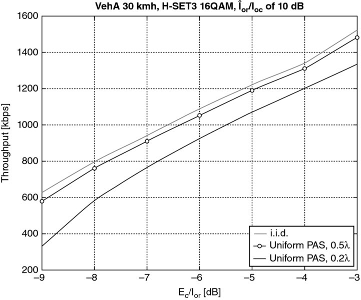
Figure 8.1 Impact to system performance for an example case with antenna correlation in the ideal case (i.i.d.) and with 2 GHz (0.5 λ) and 800 MHz cases (0.2 λ). (Holma and Toskala 2006 [2]. Reproduced with permission of Wiley)
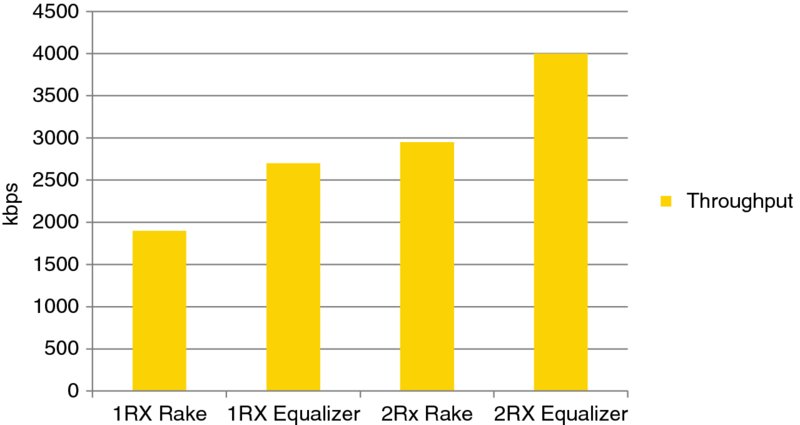
Figure 8.2 Average downlink throughput with different type of UE receivers
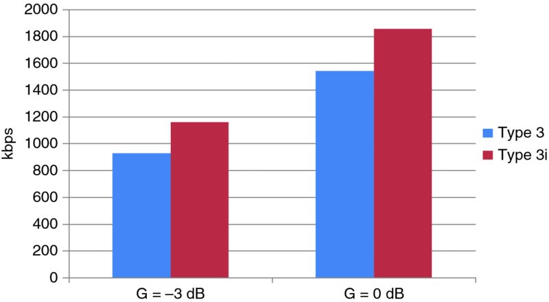
Figure 8.3 Cell edge performance with and without UE interference cancellation
A 3i or 2i capable UE may address only the dominant interferer (as in the 3GPP test case defined) or multiple interferers could also be considered if the environment has several strong signals to cancel. Aiming to cancel interference that is too weak would result in noise enhancements only due to the noisy estimates of the interfering signals.
Performance in the field with the 3i receiver compared to Type 3 receiver is also studied in the field, as shown in more detail in Chapter 10, showing similar results with the biggest gain from the 3i receiver coming in the cell edge area.
In implementations in the field, there are different types of algorithms being used, which vary from the performance point of view depending on the solution and also depending on the environment and test cases for which the solution has been optimized. An example study in Figure 8.4 shows a test case result with different Category 13 or 14 devices (supporting 15 codes with HSDPA reception and 64QAM) and Figure 8.4 illustrates the differences between different generations of devices even from the same manufacturer, proving the importance of the advanced algorithms that are chosen to be used in a particular baseband modem. Thanks to the progress of silicon technology, advanced algorithm implementation is possible even if it requires more computational capacity. Today, the advanced receiver can be implemented with a reasonable chip size, production cost, and power consumption. The impact for end user performance is significant as a modern device can provide double the data rate in good conditions compared to the older generation device with the older chip set.
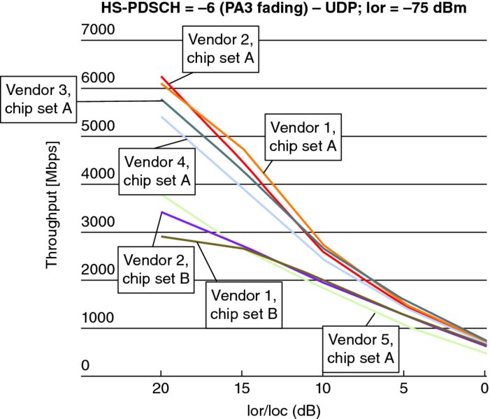
Figure 8.4 Pedestrian A 3 km/h test environment. Data from [3] courtesy of Signals Research Group
In low geometry regions, the performance is limited by Ioc rather than the multipath interference. On the other hand, the equalizer algorithm and RF circuit linearity affect the throughput in high geometry regions, where more performance difference is observed between chip sets.
From a smartphone point of view, most HSPA capable devices do not have receiver diversity, even though it is mandated for the LTE side as discussed earlier. When supporting the same band for both LTE and HSPA the necessary antennas and RF components are also already in place for HSPA receiver diversity, which is likely to make Type 3 or 3i more common in smartphone platforms too.
A further step in the receiver design is the MIMO receiver that is able to receive data from two different receiver branches, as discussed in Chapter 5. MIMO with HSDPA has not become commonly used in the devices, however, due to the problems caused for legacy devices before the introduction of the mitigation solutions discussed in Chapter 3. In the case of MIMO, one may further consider more advanced algorithms such as the Successive Interference Canceller (SIC) type of receiver. The simplest SIC receiver for two-stream MIMO is a single stage inter-stream canceller. The SIC receiver decodes the primary stream and then cancels it prior to decoding the secondary stream. The cancellation can be done using hard decisions or soft decisions. The soft decision has better reliability when the decoding of the primary stream fails but the implementation complexity is slightly high. This simple version of SIC gives most of the cancellation gain without increasing the number of Turbo decoder executions.
Also with MIMO, one can consider using Maximum Likelihood Detection (MLD). Since MLD complexity is extremely high for higher order modulation with multiple streams, simplified algorithms such as Sphere Decoding (SD) and QR Decomposition Based M Algorithm (QRM-MLD) have been proposed. There are different possibilities for the inter-stream interference cancellation with HSPA MIMO, such as those studied in [4] and references there in.
8.3 BTS Scheduling Alternatives
From a 3GPP point of view, the BTS scheduling implementation in terms of the kind of algorithm to use has been left for BTS vendor implementation; only the necessary signaling is specified to provide the scheduler with the necessary information both from the UE side, like the CQI feedback covered in Chapter 2, as well as information over the Iub interface, for example on the UE capability and possible QoS parameters.
With the initial phase of HSDPA introduction in the field with the first Release 5 devices, the type of BTS scheduler was of no major importance. When the HSDPA penetration was low, there were in many instances only a single UE in the cell, thus there was not much the scheduler could do than serve the single UE receiving data. In this case, the round robin type of scheduling was able to reach reasonable performance. The basic idea with the round robin scheduler is to serve different users one by one (assuming there is data to be transmitted) in a cyclic manner. In many cases a carrier was also shared in the power domain with legacy traffic using DCH and there were also limitations in the code space available for HSDPA use. Figure 8.5 shows an example of round robin type scheduler functionality.
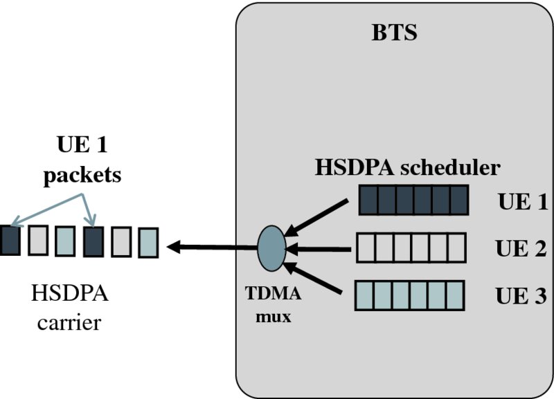
Figure 8.5 Round robin scheduler with HSDPA
The use of round robin type scheduling will not benefit from the variations in channel conditions between users as it will not try to schedule a user when the channel conditions are favorable. While a proportional fair scheduler considers basically the UE with the best channel conditions (as determined based on the Channel Quality Information (CQI) received) as the one to schedule. In order to ensure fairness it also takes into consideration that over the averaging period each UE should get the same number of scheduling instances. The most extreme form of scheduling, and also best from the system capacity, is the max C/I type scheduler, which always schedules only the user in the best channel conditions. While the total system capacity is maximized, the QoS distribution between users is poor as some users will not get a service at all while cell center UEs will have very high data rates. It is quite obvious that in a commercial system one has to use something other than a max C/I type scheduler. The proportional fair scheduler principle is illustrated in Figure 8.6.
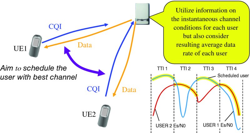
Figure 8.6 Proportional fair scheduler
The consideration of sufficient quality for each user with proportional fair scheduler can be considered with Equation 8.1, where the selection metric Mk is calculated based on the expected data rate Rk achievable as derived from CQI and the average throughput Tk experienced over the observation window.
This principle also ensures that cell edge users get schedulers and reach reasonable throughput while the data rate of the users in better conditions is also better. A scheduler could also force all users to reach an equal data rate over the averaging window, but this would lead to a clear drop in the overall system capacity.
Once the basic scheduler framework is such that suitable capacity is ensured, the next step is to ensure sufficient quality by considering the type of service. For example, services such as CS or PS voice (which both can be mapped on top of HSPA as well), or the Signaling Radio Bearer (SRB) can be given higher priority in the scheduling queue compared to the regular background PS data.
With the larger number of HSDPA users, and varying data rates, it is also important to be able to schedule users in parallel in code domains. With code multiplexing a small packet does not end up reserving the full 2-ms TTI on the carrier. Many of the earlier phase devices were also limited to using a maximum of 5 or 10 parallel codes on HSDPA, which also requires the use of code multiplexing for maximum efficiency when all or most of the carrier capacity can be used with HSDPA. Lately, most of new UEs in the market can support up to 15 codes, and thus in order to minimize the signaling overhead it makes sense to try to schedule just one UE at a time.
The operation with HSUPA also needs scheduling operation to control the uplink interference level, as addressed in Chapter 2. While the code resource is not the limiting factor now due to the UE specific code tree under the UE specific scrambling code, the key is to manage the power levels and resulting total noise rise. The MAC header info on the buffer status and power headroom enable decisions in the HSUPA scheduler on whether to increase or decrease the data rate of a particular user with relative or absolute grants, but the key difference from downlink is that normally some minimum data rate is transmitted by each user, while in downlink with HSDPA a UE might not get allocation at all during a particular TTI as maximum of four HSDPA users can be normally allocated simultaneously within a single TTI. The HSUPA scheduler principle is illustrated in Figure 8.7, with the BTS HSUPA scheduler determining first, based on the noise rise, whether load should be increased or decreased and then determining which user should be impacted by the actions in increasing or decreasing the uplink data rate (in principle the power ratio allocation, effectively converting to a particular data rate).

Figure 8.7 HSUPA scheduler
8.4 BTS Interference Cancellation
With all users sharing the spectrum, it is well known that a WCDMA system is interference limited. This is even more the case in the uplink where users do not have orthogonality like the channelization codes in the downlink, though depending on the channel the orthogonality is in many cases largely reduced.
Similar to the earlier introduced 3i receiver for UE, in the BTS side it is also possible to cancel part of the interference caused by other users in the system. This is an item that has been investigated a lot since the 1990s. The interference cancellation or multiuser detection in a broader sense can be done in many ways. The linear equalizer type detector, such as the decorrelating detector, is a linear filter trying to suppress the interference. The Interference Cancellation (IC) receiver aims to actually estimate the interference signal and then to subtract that from the desired signal to gain better detection and decoding outcomes.
The type of IC receiver can be further classified as Serial (or Successive) Interference Cancellation (SIC) or as Parallel Interference Cancellation (PIC). The use of a SIC receiver aims to detect one user at a time, cancel that, then proceed to detecting the next user, while the PIC receiver performs the operation in parallel to all users. The use of SIC receivers easily creates some issues with the latency, especially when the number of users is large.
Often, such a receiver aims to have multiple iterations to allow better reliability, thus operating as a multistage receiver. An example principle of a PIC receiver for two users is shown in Figure 8.8, with the first phase being a traditional receiver like a Rake receiver, and then, based on the decisions in the first stage, the interference would be cancelled from both users and further stages would then aim to improve the reliability.

Figure 8.8 PIC receiver for two users
Different approaches also exist based on which signal to regenerate the interfering signal to be cancelled. One may try to estimate the signal before turbo decoding, as studied for example in [5], or shown in Figure 8.8.
Another approach is to aim to decode the block of symbols for better reliability and take the signal for regeneration and cancellation operation on after convolutional or turbo decoding has been carried out, as shown in Figure 8.9. Such an approach results in better reliability of the signal to be cancelled. Counting on symbols that are too unreliable, with the interfering signal regeneration and cancellation before channel decoding, could in some situations lead to noise enhancement rather than actually improving detection. The cancellation could be done at chip level (by regenerating the spread signal as part of the IC operation) or at the symbol level (by considering, for example, the correlation properties between the codes and then removing the impact at the symbol level after the Rake receiver) as shown in Figure 8.9.
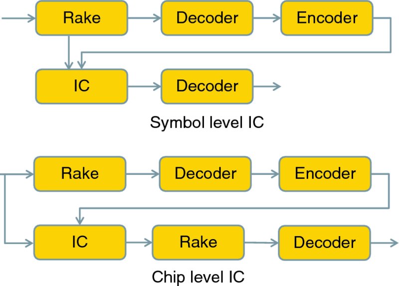
Figure 8.9 Symbol and chip level IC using output from the channel decoder
What was, in the 1990s, only of academic interest has become a reality with the increased computational powers in HSPA-capable base stations, first in narrowband CDMA, as smaller bandwidth is easier to handle due to the small chip rate, but lately as enabled in the WCDMA commercial products as well.
The use of HSUPA with turbo encoding and physical layer retransmission creates some additional challenges for the interference cancellation operation, especially if using the solution as in Figure 8.5. With efficient channel coding and HARQ the resulting signal energy at the receiver is very low and BER for channel symbols/soft bits is very high. Thus making decisions on individual symbols is not fully reliable in all situations. There are also benefits from the use of HSUPA compared to Release 99. With the higher peak data (and thus also smaller spreading factors) rates there are now individual users that momentarily typically dominate the interference situation. Addressing such a high data rate user with interference cancellation allows a clearly improving uplink data rate, especially when the solution is such that it also enables channel equalizer functionality.
The capacity benefit of an interference cancellation solution depends on both the cancellation efficiency and also on the ratio of the own cell interference and neighbor cell interference in the particular environment. For the case with identical noise rise for both the case with and without interference cancellation, the capacity can be given as:
With β = to the interference cancellation efficiency (studies to be in the order of 25–40% in [1]) and i is the ratio of other-cell interference to own-cell interference. Thus, for an equal share of interference from other cells and own cell, and 40% efficiency, the resulting capacity gain would be in the order of 35%.
An example performance result is shown in Figure 8.10 for different cancellation efficiencies when the own cell and neighboring cells have an equal contribution to the interference level. Obviously the close to 100% interference cancellation is a rather theoretical case as there will be always some errors in the estimation, finite word length effects in implementation, as well as missing propagation paths in the cancellation process and so on; imperfections that degrade the practical performance.
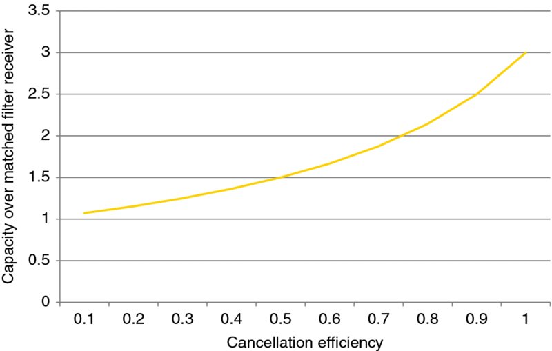
Figure 8.10 Example BTS interference cancellation performance
The performance with an example interference cancellation solution is shown in Figure 8.11, illustrating how the system capacity would normally degrade due to the extra overhead with a larger number of HSUPA users, while with the use of BTS IC the capacity level is mostly retained even with the increased user numbers. The performance in a single user case would not see too much impact from the IC operation, since own transmission does not degrade the performance that much but, as the total power used by other users increases, then the overall performance goes down unless IC is used. As shown in the Figure 8.11, the performance improvement varies depending on the scenario from roughly 15 up to 80% for the larger number of simultaneous users case. From the end user data rate (average) point of view, the impact is quite significant especially in heavily loaded cases, as with seven HSUPA users (and voice traffic) one ends up sharing only approximately 1.8 Mbps total capacity while with BTS IC one gets to share approximately 3.2 Mbps capacity among active users.
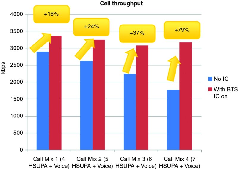
Figure 8.11 Example BTS IC measurement result of the achievable performance improvement
8.5 Further Advanced UE and BTS Algorithms
From the UE side, the link performance is further impacted by, for example, the solutions used for turbo decoding, deciding which CQI value to transmit to NodeB, or creation of the downlink power control commands (in case of DCH used for voice). Such algorithms mostly have the minimum performance criteria coming from the 3GPP performance specifications, ensuring sufficient performance for those algorithms. The mobility related algorithms, such as those used for cell search and neighbor cell measurements, are also essential to ensure good link maintenance and avoid unnecessary radio link failures.
One of the areas under investigation in 3GPP is Network Assisted IC (NAIC), where the UE would aim to cancel the strongest interferer and would obtain information from the network to make the cancellation work better. In the simplest form the UE would be provided with information on the modulation and channelization codes used, thus basing the cancellation on the soft channel bits estimates. If the solution as described in Figure 8.6 were to be used then more information, such as transport block size, would be needed to enable the actual turbo decoding operation to regenerate and subtract the interfering signal. More information on the NAIC for HSDPA UE can be found from [6]. Another approach is to aim to perform a similar operation blindly, by simply aiming to detect the interfering signal blindly. Obviously then the actual turbo decoding of the strongest (if aiming only to cancel the dominant interferer) interfering signal is not feasible as it is missing information such as the block size used with encoding and the redundancy version in use.
In the BTS algorithms the good power control algorithm was of major importance, starting from Release 99. Further, the solutions in advanced antenna technology in the form of beamforming antennas also require sufficient intelligence in the NodeB to benefit most from such a solution. The WCDMA-based UEs have limitations in terms of dealing with UE-specific phase reference, thus rather than operating individual beams one rather uses CPICH-based beams with vertical sectorization, for example, as shown in Figure 8.12 where each cell operates as a cell on its own and thus uses its own CPICH. 3GPP is carrying on further work in this area to enable 3D-channel models. While the work formally is valid for LTE, typically a channel model is not going to be technology specific, thus enabling the use of channel models for HSPA related studies as well. The latest versions of 3GPP 3D-channel models can be found from [7].
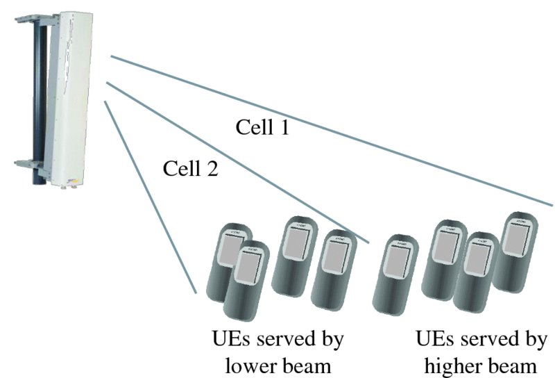
Figure 8.12 Operation with vertical sectorization with HSDPA
8.6 Conclusions
In this chapter we have looked at some of the developments and possibilities of advanced UE and NodeB algorithms. Since the early days of WCDMA introduction, the technology evolution on both the UE and NodeB sides has enabled several technological improvements to also be introduced commercially in the field. One example area is interference cancellation, which has been made commercial both on the UE and on the NodeB sides.
Some of the improvements are based on specification development, like the advanced UE receiver, while most of the algorithm ones, such as BTS IC, are dependent on the manufacturer of the particular equipment. Even for the case of a 3GPP feature such as the advanced UE receiver, where performance requirements exists, the 3GPP requirements are rather representing a reference implementation while actual state-of-the-art implementations are likely to be able to perform clearly better as the studies performed on different HSPA chip sets were able to show too. The type of HSPA chip set used may have a large impact on the resulting performance, especially with higher geometry values (closer to the base station).
3GPP is working with studies in the area of performance improvements more driven by LTE, but clearly where applicability for HSPA can be seen too. Examples of such items are NAIC, with work items for LTE, termed Network Assisted IC and Suppression (NAICS) or 3D-channel modeling for enabling 3D-beamforming studies. These pave the way for new potential enhancements that could be introduced in the networks, improving state-of-the-art HSPA network performance even further. More Release 12 items are covered in Chapter 15.
References
- Holma, H. and Toskala, A. (2010) WCDMA for UMTS, 5th edn, John Wiley & Sons, Ltd, Chichester.
- Holma, H. and Toskala, A. (2006) HSDPA/HSUPA for UMTS, John Wiley & Sons, Ltd, Chichester.
- Signals Ahead, Volume 7, No. 5 April 26, 2011, www.signalsresearch.com.
- Yu, H., Shim, B. and Oh, T.W. (2012) Iterative interstream interference cancellation for MIMO HSPA+ system. Journal of Communications and Networks, 14(3), 273–279.
- Toskala, A., Hämäläinen, S. and Holma, H. (1998) Link and system level performance of multiuser detection CDMA uplink. Wireless Personal Communications: An International Journal Archive, 8(3), 301–320.
- 3GPP Technical Report, TR 25.800, “Study on UMTS heterogeneous networks” v 12.0.0 September 2013.
- 3GPP Technical Report, TR 36.873, “3D channel model for LTE”, v 2.0.0, March 2014.