
5
HSDPA Multiflow
Thomas Höhne, Karri Ranta-aho, Alexander Sayenko, and Antti Toskala
5.1 Introduction
This chapter presents the Release 11 HSDPA Multiflow, which was introduced to address and improve the cell edge performance of the HSDPA system. As described in Chapter 2, the Release 5 based HSDPA connection is provided from a single cell only, even though the active set may contain more cells. With HSDPA Multiflow, there is the possibility of obtaining additional diversity and boosting the cell edge data rate by receiving several data streams from neighboring cells. In the following, we first describe the Multiflow principles, before highlighting specific architectural and implementation aspects. The chapter is then concluded with a Multiflow performance evaluation.
5.2 Multiflow Overview
Multiflow is designed to improve the throughput of cell edge users and network-wide capacity by RRM load balancing. It belongs to the category of cell-aggregation features, a number of which were studied and presented in [1] as part of the study item that led to the Multiflow work item effort [2]. Multiflow is very similar to multicarrier HSDPA, with the generalization that cells do not need to have the same timing and can be on the same frequency. Multiflow also has a similarity with the LTE-Advanced dual connectivity, which at the point of writing is being studied as a feature for Release 12 [3]. A comparison to other multipoint and aggregation techniques is provided at the end of this chapter.
In a Multiflow transmission a UE, which is situated at the border between two cells and has those cells in its active set, may receive data independently and concurrently from several cells. The cells may belong to the same site, leading to intra-site Multiflow, or may belong to different sites, leading to inter-site Multiflow, as shown in Figure 5.1. From a UE perspective, gains are visible because twice as many transmission resources can be put at its disposal. On a system level, gains materialize when either of the cells has free resources that are put to use with Multiflow. This works best in low–medium load situations, and Multiflow gains are thus best understood as short-term load balancing gains between cells.
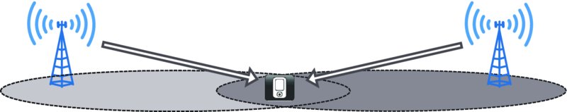
Figure 5.1 NodeBs schedule and transmit data independently to a UE at the cell edge
Unlike LTE Rel-11 CoMP feature, Multiflow does not require coordination among sites and allows for independent cell schedulers, enabling easy inter-site deployment and comparatively low implementation complexity in the network. In fact, no new hardware requirements arise on the network side. From the UE implementation perspective, the Multiflow functionality is based on existing HSDPA multicarrier architecture.
In summary, it is the following aspects of Multiflow that stand out and have led to a speedy adoption in specifications and implementation:
- operator-friendly network capacity improvements by better utilization of unused resources;
- cell-edge user throughput benefits (of up to 50%, as shown towards the end of this chapter);
- software-only network implementation without a requirement to coordinate or synchronize NodeBs;
- reliance on existing UE hardware building blocks.
5.2.1 Multiflow Principle
In intra-site Multiflow, RNC sends all data to one NodeB, which distributes packets between the cells, making the overall functionality almost identical to multicarrier HSDPA. In inter-site Multiflow the source data coming to the RNC is split at the level of RLC PDUs and distributed between two independent flows sent to different sites, as shown in Figure 5.2. NodeBs of both sites schedule and transmit the RLC PDUs independently of each other. In turn, the UE merges PDUs received from the two NodeBs and re-orders them into a single stream of PDUs with consecutive sequence numbers before delivering them to higher layers.
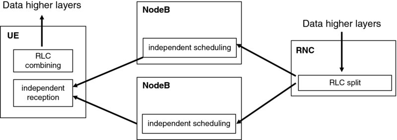
Figure 5.2 Data flow split, independent scheduling, and combining at the UE for inter-site Multiflow
Multiflow has been designed to support transmission from only two different sites. The reason is that transmissions from three or more sites improve performance only marginally. Furthermore, more than two sites will result in having potentially more than two cells with different timing, as will be explained later in Section 5.6.3.
5.2.2 Multiflow Configurations
In multicarrier HSDPA, the NodeB transmits content to the UE on several carriers: up to eight carriers may be used for transmission to a UE as per 3GPP Release 11 functionality. Multiflow configurations are limited to two cells on the same frequency and two NodeBs transmitting on at most two frequencies, leading to a total amount of aggregated cells of four. The naming convention for the different configurations is:
Of all conceivable combinations three configurations have been agreed in Release 11:
- SF-DC single frequency – dual cell.
- DF-3C dual frequency – three cell.
- DF-4C dual frequency – four cell.
The SF-DC configuration has already been illustrated in Figure 5.1, and Figure 5.3 shows the example of DF-3C with the assisting secondary cell on the second frequency (an alternative DF-3C scenario is to configure the cell on the second frequency at the serving NodeB). The group of cells that do not belong to the serving NodeB are designated as “assisting.”
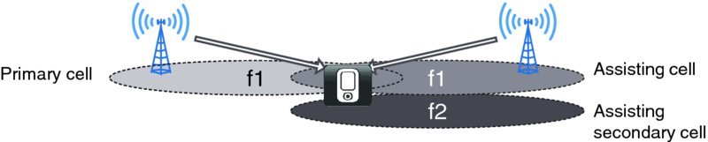
Figure 5.3 Multiflow terminology for the example of DF-3C
It is worth noting that both DF-3C and DF-4C Multiflow configurations can be applied to non-adjacent and dual-band deployments. Referring to Figure 5.3, the cell on frequency 1 and on frequency 2 can be either adjacent in frequency or there can be a gap between them, if an operator does not have a contiguous spectrum. The same logic can be applied to dual-band, when the aforementioned cells can be in different bands.
5.3 Multiflow Protocol Stack
In intra-site SF-DC configuration the data flow is split at the MAC-ehs level, a protocol stack view of which is shown in Figure 5.4 (see also [4], section 22). The intra-site Multiflow protocol stack does not differ from that of a multicarrier HSDPA deployment in that the RNC sends all data to the same NodeB, which will schedule data in two cells. However unlike in multicarrier HSDPA the cells will belong to different sectors and reside on the same frequency. Furthermore, unlike in multicarrier HSDPA, the cells will also have different timing.
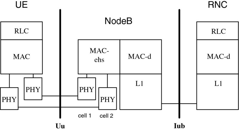
Figure 5.4 Protocol architecture of intra-site SF-DC Multiflow. In the figure, data flows from RNC to UE
In inter-site SF-DC the data is split at the RLC level, as shown in Figure 5.5. When compared to the figure, now RNC splits data between two different NodeBs.
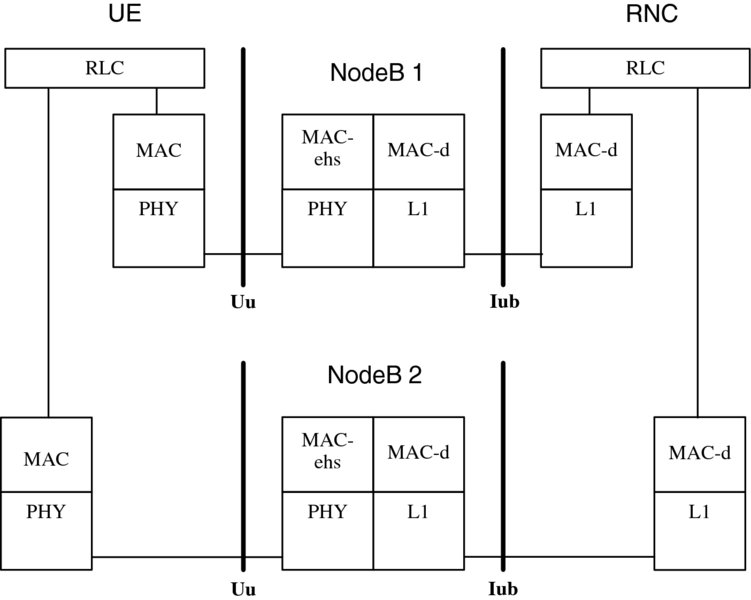
Figure 5.5 Protocol architecture of inter-site SF-DC Multiflow. The RNC splits the RLC PDUs into two MAC-d flows
For a DF-3C deployment, a combination of the inter-site split at the RLC level and legacy multicarrier scheduling at MAC-ehs level is employed, as shown in Figure 5.6. While the upper part of the figure looks the same as that of intra-site Multiflow in Figure 5.4, the difference is that two cells belong to the same sector and thus have the same timing.
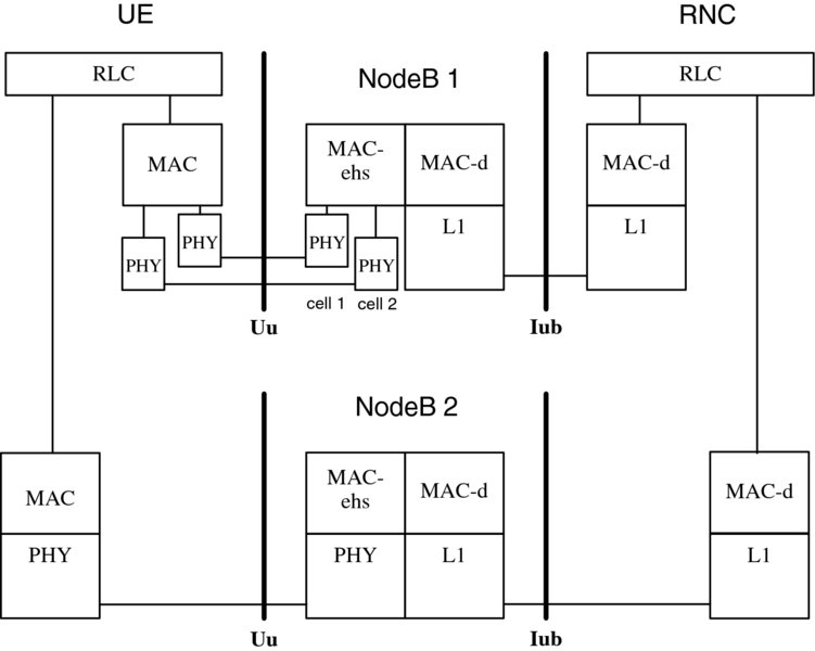
Figure 5.6 Protocol architecture of DF-3C Multiflow. The RNC splits the RLC PDUs into two MAC-d flows and one NodeB schedules data over two cells
In inter-site Multiflow, as shown in Figures 5.5 and 5.6, the data can be forwarded over the Iur interface using the frame protocol if the second NodeB is connected to a different RNC.
5.4 Multiflow Impacts on UE Architecture
A Multiflow UE must be able to receive, equalize, and decode data concurrently from both cells that are configured for Multiflow operation. First, the UE must demodulate the received signals from several cells on the same frequency, imposing a new requirement compared to earlier HSDPA receivers. Just as in multicarrier, the cells will have different channel responses, but unlike in multicarrier HSDPA the cells also will have different frame timing, and for inter-site potentially different frequency error because of Doppler and because of clock drift. The reception of two Multiflow cells on the same frequency but with different timing and different frequency error and so on could in principle be carried out with one receiver chain only. However, in practice re-using multicarrier receiver chains for that purpose is easier, and in fact specifications have been written to mandate a multicarrier capability for a Multiflow UE. Figure 5.7 exemplifies a high-level physical layer block diagram for a dual-carrier dual-antenna UE receiver (a more extensive review of multicarrier receiver architectures is provided in Chapter 14). For Multiflow, the RF front-end of the second receiver chain of the multicarrier receiver blocks has been tuned to the carrier frequency of the neighboring cell. In the example, the neighboring cell has the same frequency, but of course a different scrambling code and a different frame timing.

Figure 5.7 Typical UE receiver architecture for a Multiflow UE, supporting dual-carrier and SF-DC
The decoding of transmissions that arrive simultaneously with about equal receiver strength on the same carrier frequency make it necessary to employ at least an interference suppressing receiver, such as a type3i receiver, discussed in Chapter 8.2.
5.5 Uplink Feedback for Multiflow
5.5.1 HS-DPCCH Structure with Multiflow
As background, we recall that for multicarrier HSDPA the uplink feedback for all cells is carried on a single HS-DPCCH feedback channel, on the paired uplink frequency of the primary downlink carrier. The uplink feedback consists of the downlink CQI and the acknowledgements (A/N) for downlink HARQ transmissions, and its format depends on the number of configured cells and whether MIMO is enabled. For instance, a four-carrier transmission with no MIMO could have a HS-DPCCH as shown in Figure 5.8.
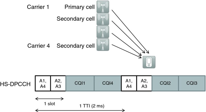
Figure 5.8 The HS-DPCCH uplink feedback format for 4C-HSDPA
In the chosen example, every TTI carries the HARQ acknowledgments (Ai) for all four cells, while the four CQI values (CQIi) are time multiplexed over two TTIs. We further note that in multicarrier HSDPA, except for the primary cell, the position of a secondary cell's feedback within the HS-DPCCH can be configured freely and is referenced with an index carried in the RRC signaling.
For Multiflow, the feedback structure is almost identical with the difference that the position of a HARQ acknowledgement and a CQI within the HS-DPCCH depends on which site (or cell group in 3GPP specifications) it belongs to. Thus, the position of the feedback for a cell within the HS-DPCCH is fixed and is governed by whether a cell belongs to the serving or the assisting NodeB and whether it is the primary serving/assisting cell or the secondary serving/assisting cell. As an example, the DF-4C non-MIMO Multiflow feedback format is shown in Figure 5.9.
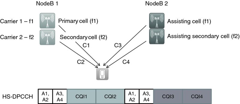
Figure 5.9 The HS-DPCCH uplink feedback format for Multiflow DF-4C
With this design in DF-3C or DF-4C Multiflow where the feedback spans over two TTIs, both serving and assisting NodeB will have to read CQI information from only one TTI and decode the CQI only of cells belonging to the corresponding NodeB. Furthermore, dynamic carrier activation/deactivation becomes possible without the requirement of cumbersome inter-site coordination. A third advantage of the feedback grouping approach lies in the relative A/N codebook performance, compared to a design where a NodeB has less a priori knowledge of the possible values that it is about to receive: in some code designs the awareness of a cell's activation status has been built-in allowing an overloading of codewords and larger codeword distance. With both NodeBs not necessarily knowledgeable about the activation status of all cells, the A/N codebook needed modification. With grouping of feedback according to sites the modifications could be limited to one particular MIMO-configuration, see [5] section 4.7.3D.1.
For SF-DC the HS-DPCCH structure follows the dual-carrier format, as shown in Figure 5.10, allowing a direct reuse of the feedback design implemented for dual-carrier HSDPA.
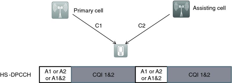
Figure 5.10 The HS-DPCCH uplink feedback format for Multiflow SF-DC
A complete list of the configuration options and their feedback formats has been tabulated in [5] section 4.7.4.3.
5.5.2 Dynamic Carrier Activation
Multicarrier HSDPA allows for the activation and deactivation of already configured cells by means of HS-SCCH orders. This functionality was introduced to enable greater battery savings, as well as better uplink spectral efficiency, as the UE does not need to report CQIs for deactivated cells, and in dual-band receivers may also switch off one receive chain. Dynamic carrier (de-)activation can also be applied to Multiflow, with some restrictions. While in multicarrier HSDPA the serving NodeB can deactivate any carrier, in inter-site Multiflow a NodeB may issue the HS-SCCH carrier activation order only for the cells that it controls, thereby avoiding changes to the feedback TTI that a given NodeB needs to decode. A deactivation of the assisting cell on the primary frequency is not specified.
An example of the change of uplink feedback to a more efficient format is shown for a DF-3C configuration, where first all cells are activated (Figure 5.11), and then the secondary assisting cell in NodeB2 (cell 3) is deactivated (Figure 5.12): in the second TTI of the feedback the CQI format is changed, however, only the part of the HS-DPCCH that needs to be understood by NodeB2 is impacted, whereas the feedback structure for NodeB1 remains the same.
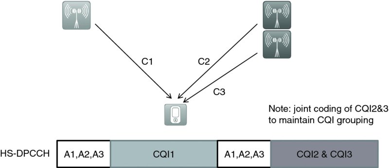
Figure 5.11 DF-3C feedback with all carriers activated. In this Multiflow configuration the CQIs of the second TTI are jointly coded, as they belong to the same NodeB
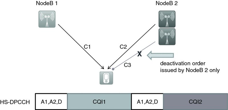
Figure 5.12 DF-3C feedback with one carrier deactivated
5.5.3 Timing of Uplink Feedback
In HSDPA the uplink HS-DPCCH HARQ A/N feedback is transmitted 7.5 slots or 2.5 TTIs after the HS-DSCH has been completely received. In Multiflow, the HS-DPCCH contains the feedback of up to four HS-DSCH cells, which may belong to two different sites, which in turn in general will be unsynchronized. Furthermore, even in the intra-site Multiflow, cells belonging to different sectors may have a different timing, as configured by the so-called T_cell parameter. An increase in the latency of the feedback transmission would result in a reduction of the throughput or would require larger numbers of HARQ processes, neither of which is desirable. Instead of increasing latency one could also speed up processing of the HARQ acknowledgments (and CQIs) for the cells that appear later. In the worst case, one cell lags the other by 1.5 slots, and hence a new requirement was introduced for the UE to process the downlink transmissions within 6 slots, instead of within 7.5 slots.
As the feedback for two different sites (or cell groups) is being bundled into one feedback message, one of the cells can be defined as leading, and is referred to as the time reference cell, see Figure 5.13. In case the timing difference between cells becomes larger than 1.5 slots, for instance because of clock drift, the network will reconfigure the other cell to take the role of time reference. To avoid a reconfiguration ping-pong effect when the timing difference is close to exactly 1.5 slots, an additional hysteresis of ±20 chips was agreed, see Section 7.7.2 in [12]. It is worthwhile pointing out that the role of time reference cell is independent of whether a cell is assisting or not.
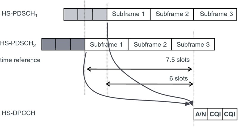
Figure 5.13 HS-DPCCH uplink timing for inter-site Multiflow
5.5.4 HS-DPCCH Power Levels
In the chosen design for relaying feedback in the uplink direction, both NodeBs receive and decode one and the same HS-DPCCH sent by the UE. This is possible because even in non-Multiflow HSDPA operation the UE's HS-DPCCH power is dimensioned such that it can be received by any cell in the active set, that is, also by inter-site neighbor cells. This safety margin is required as a UE may have already transitioned into a new cell's area, but still needs to maintain connectivity with the source cell before a serving cell change can be carried out. Nevertheless, in order to allow for a wider Multiflow area, which requires a better uplink control channel coverage, it was decided that the HS-DPCCH amplitude boosting factor βhs be increased from a factor of 3 relative to the uplink DPCCH to a factor of close to 5, see section 4.2.1.2 in [6]. The additional boosting factor translates into increasing the maximal power gain factor from 9.5 to 14 dB. The additional boosting factor is specified as a separate Release 11 UE capability, which can be applied outside of the Multiflow operation. A UE implementing Multiflow must always indicate this capability.
HS-DPCCH boosting is especially useful in HetNet co-channel deployments (see Chapter 7), where a small cell of lower transmittal power is placed within the coverage area of a macro cell. At the border between the macro and small cell, at a point of equal downlink strength, the uplink signal strength at the macro and small cell NodeBs receivers will be very uneven, creating a problem that is referred to as the uplink/downlink imbalance. Thus, even at the point of equal downlink strength, the HS-DPCCH must be allocated more power than would be required if the small cell were to receive it alone, in order for the macro to be able to decode it. A way of helping the HS-DPCCH reception beyond a possible uplink imbalance of 14dB is to raise the overall SIR target level at the small cell beyond what is required there, to satisfy the needs at the macro.
The high HS-DPCCH power levels that may be needed for a larger Multiflow area can be reduced by using repetition and combining. For instance, the same CQI can be repeated over one or more consecutive HS-DPCCH sub-frames and the energy of a single CQI message is thus spread over multiple sub-frames reducing the peak power requirement in proportion to the amount of repetition. The downside of CQI repetition is that it limits the frequency of fresh CQI reports, but may nevertheless be useful. ACK/NACK repetition is also possible, but in inter-site Multiflow, where the main usefulness of repetition lies, it is not possible to coordinate the transmissions of the two NodeBs making dynamic repetition difficult. Furthermore, ACK/NACK repetition cuts the achievable data rates as the UE cannot be scheduled with data in consecutive sub-frames.
5.6 RLC Impact
5.6.1 RLC Timer_Reordering
One of the challenges of inter-site Multiflow transmission is that data is split by RNC and sent over two different NodeBs, who may experience different delays, link speeds, loads, and so on. Differing channel and load conditions may lead quite easily to a situation where a UE receives a set of packets without having received a set of preceding packets from another NodeB, which can be either under transmission or can be still in the NodeB buffer waiting for their scheduling turn. This situation, where RLC PDUs may arrive to a UE not in the same order as they were sent, creates a so-called skew problem. In legacy functionality the RLC layer perceives absence of a particular RLC PDU as indication that its transmission has failed over the radio link. This is a safe assumption, because the underlying HARQ layer has its own sequence numbering and re-ordering and in the non-Multiflow case it will ensure in-sequence delivery. Thus, if a certain RLC PDU is missing at the RLC layer, then a NACK is triggered and sent in a corresponding RLC STATUS PDU message. In inter-site Multiflow, however, the absence of an RLC PDU can be either due to a true transmission failure or due to the fact that it is still waiting in a buffer inside another NodeB. If a UE configured with inter-site Multiflow reported any missing RLC PDU as NACK back to the RNC, as in the legacy case, performance would decline because the RNC would re-transmit PDUs that are still in the NodeB buffer, and the same PDUs might be transmitted over the Uu interface twice. This behavior is illustrated in an example in Figure 5.14.
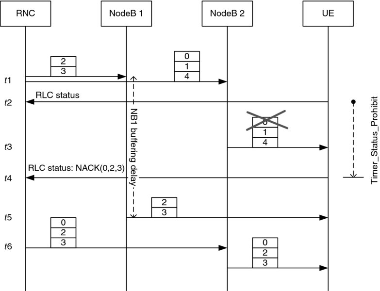
Figure 5.14 RLC ACK/NACK with the reception of out-of-sequence PDUs. PDUs 2 and 3 are transmitted to the UE twice
In the example, NodeB1 has a buffering delay t5-t1, but NodeB2 is able to transmit earlier, leading to skewed reception at the UE. While RLC PDU 0 is genuinely lost, and PDUs 2 and 3 are still in the NodeB1 buffer, the UE counts PDUs 0, 2, and 3 as missing once it receives PDU 4. Even though there is Timer_Status_Prohibit that prevents a UE from sending RLC STATUS messages too frequently, there is always a chance that upon its expiry a UE will have gaps in RLC sequence numbers. Referring to the example above, the RLC STAUS message will contain NACKs for PDUs 0, 2, and 3, which in turn will trigger the RNC to resend them. Hence PDUs 2 and 3 are transmitted twice over the air interface.
To address the problem that a UE cannot know the exact reason for a missing PDU, and sending back NACKs for all the missing PDUs is not optimal, a new RLC timer “Timer_Reordering” was adopted. Its purpose is to achieve a tradeoff between how long a UE waits for a missing PDU versus the time when the missing PDU is finally reported as NACK in the status report. Figure 5.15 illustrates how, for the above example, the sending of the NACK is delayed, and unnecessary retransmission of PDUs 2 and 3 is avoided. Once a UE receives PDU 4 and detects that PDUs 0, 2, and 3 are missing, it starts the Timer_Reordering timer for those PDU thus delaying the transmission of NACKs. In the example, PDUs 2 and 3 arrive before the expiry of that timer, and the NACK will include only PDU 0.
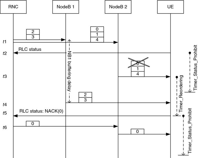
Figure 5.15 RLC ACK/NACK with the reception of out-of-sequence PDUs. Timer_Reordering eliminates unnecessary re-transmissions
Timer_Reordering is mandatory for a UE and is optional for the network in the sense that the network provides the exact value for this timer and, if it is omitted, then a UE does not activate the timer at all. Thus the network may deactivate this timer at the UE if it has other mechanisms to overcome the problem when NACK is received for some PDUs that were still under transmission. The value for Timer_Reordering may vary from 50 ms to 1 s. The exact value is chosen by the network based on its anticipation of how fast the flow control can work and the NodeB scheduling strategy that has a direct impact on the delay that packets may experience in the NodeB buffer.
5.6.2 RLC Reset
Along with a new RLC timer described in the previous section, another RLC enhancement introduced for Multiflow is a different handling of the RLC STATUS PDU. Before the introduction of the Multiflow operation, whenever a UE received the RLC STATUS PDU with a sequence number outside of the RLC transmission window, it initiated immediately the RLC RESET procedure. This functionality was needed to achieve robust behavior: if a UE received an out-of-sequence status PDU it might be a sign of severe RLC state machine mismatches. However, with Multiflow the RNC may reply to the UE uplink traffic by sending the STATUS PDU message either over the serving, or assisting, or even both the serving and assisting links. Such RNC behavior may easily lead to a situation when RLC STATUS PDU messages arrive at the UE in a different order, thus triggering unnecessarily the RLC RESET operation. It was decided that the RNC should have the possibility of deciding flexibly how to send RLC feedbacks and, as a result, it was agreed that for the inter-site Multiflow operation, no RLC RESET operation should be initiated under these circumstances. At the same time, a UE still initiates the RLC RESET procedure in case of intra-site Multiflow to be functionally close to the multicarrier HSDPA.
5.7 Iub/Iur Enhancements
5.7.1 Flow Control
When the RNC provides data to a NodeB, it does so based on “credits” that the NodeB has given to the RNC. The NodeB's credits are based on its buffer status. If the NodeB buffer is empty, more credits will be provided. If the buffer is full, for instance because the NodeB was not able to transmit data, it will grant zero credits to the RNC. This process is called flow control. The calculation of the number of credits is an implementation choice; a typical procedure would seek to maintain a certain target buffer size in relation to the average transmission rate. This target buffer size will also depend on the frequency at which flow control credits are provided to the RNC and the speed at which the RNC can hence react to the NodeB having already emptied its buffers. A faster flow control loop allows for smaller NodeB buffers and delays, a longer flow control period requires larger buffers to avoid a situation where a buffer underrun occurs and transmission opportunities are missed.
In inter-site Multiflow – as there are two NodeB buffers to fill – the RNC maintains two independent flow control loops, as shown in Figure 5.16. The total burst rate and the user experience achieved at the UE will be governed not only by the sum of the individual link speeds, but also by when data from each link arrives to the UE. We note that the overall duration of a data burst is smallest when both NodeBs finish their transmissions at the same time. Thus, the RNC should run an efficient flow control mechanism to ensure an even data split in the sense that one cell does not transmit for longer than the other, which is important in order to achieve maximal throughput gains for the UE.
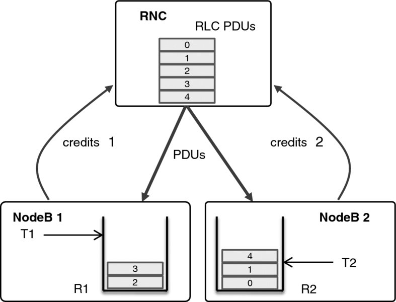
Figure 5.16 Flow control in inter-site Multiflow with buffer targets T1 and T2
5.7.2 Multiflow Extensions
As mentioned in the previous subsection, an efficient flow control running in RNC should aim at ensuring that NodeB buffers will be emptying at the same moment thus avoiding skew as much as possible, skew for which the UE RLC Timer_Reordering would hold on sending back the RLC STATUS PDUs. However, changing load conditions in the serving and the neighboring cells may lead to the situation when data in the NodeB buffer will stall for a noticeable moment of time. Since Multiflow allows for sending data over two paths to a UE, one can consider several options on how to tackle the stalled data and potentially resend it over another link. All these considerations have led to the introduction of several new mechanisms for the Iub/Iur interface: a possibility for the RNC to discard data in the NodeB buffer, and a possibility to let the RNC know that certain PDUs were dropped from the NodeB buffer.
Both new mechanisms rely upon a new sequence number field inside the HS-DSCH DATA FRAME that carries data from the RNC towards the NodeB. If RNC wants to remove data from the NodeB buffer, it uses the aforementioned sequence number to indicate which packets must be dropped. Similarly, a new control frame HS-DSCH PDU DROP INDICATION was introduced to signal back to the RNC which PDUs were dropped from the NodeB buffer. It is worth noting that while HS-DSCH DROP INDICATION allows indication that an individual RLC PDU was dropped by NodeB, the RNC cannot ask NodeB to remove an individual RLC PDU. All the PDUs, which were previously sent in the HS-DSCH DATA FRAME by the RNC, would be discarded from the NodeB buffer.
5.8 Multiflow Combined with Other Features
5.8.1 Downlink MIMO
Multiflow data transmission can be combined with downlink 2 × 2 MIMO in single-stream and dual-stream modes. MIMO functional behavior with Multiflow remains unchanged and only HS-DPCCH formats have been modified as explained in Section 5.5.1.
It should be noted that the combination of Multiflow and dual-stream downlink MIMO will result in four MIMO streams, which requires a UE to have four Rx antennas to allow for a rank-four channel reception. At the same time, combination of single-stream MIMO and Multiflow can still be achieved with two Rx antennas. These considerations led to a design where a UE can signal independently whether it supports MIMO with Multiflow or not, and in the case that it does, whether it is limited only to the single-stream MIMO or both single-stream and dual-stream modes.
The downlink 4 × 4 MIMO HSDPA transmission introduced in Release 11 is not supported in combination with Multiflow.
5.8.2 Uplink Closed-Loop Transmit Diversity and Uplink MIMO
Along with the Multiflow feature aiming at improving the downlink performance, 3GPP Release 11 has introduced Closed-Loop Transmit Diversity (CLTD), which improves system performance in the uplink direction by allowing NodeB to steer the UE uplink transmission beam in such a way that the received power is maximized. It facilitates improving the cell edge performance as a UE can transmit at higher data rates, where it otherwise would be power limited. Of course, neither Multiflow is dependent on uplink CLTD, nor does uplink CLTD require a UE to support Multiflow. However, since both features improve the cell edge performance, a combination of these features was discussed and agreed in 3GPP. Thus, the network can configure them simultaneously if a UE supports these features.
Uplink MIMO is another Release 11 feature that was introduced to boost the uplink peak rates (see Chapter 3). Even though uplink MIMO is not likely to be used at the cell edge, there is a scenario when Multiflow is configured between two cells belonging to the same site. In this case, a UE can be close to the NodeB, and thus Multiflow can be also combined with uplink MIMO.
5.8.3 DTX/DRX
3GPP Release 7 introduced a set of features under the Continuous Packet Connectivity (CPC) umbrella, where the UE DTX and DRX were specifically aimed at reducing the UE power consumption and uplink capacity consumption. For the sake of technical clarity, we recall that the main CPC features are downlink DRX and uplink DTX. The uplink DTX allows a UE to avoid transmitting continuously uplink control and pilot channels, if it does not have any data or HS-DPCCH feedback to send. Uplink DTX can be configured alone without downlink DRX. In turn, the downlink DRX allows a UE not to listen to the downlink control channels, whereupon the Uplink DTX must be also configured because a UE cannot transmit without listening to the uplink power control commands in the downlink. The CPC feature is explained in more detail also in Chapter 4.2.
In the case of intra-site Multiflow, both the uplink DTX and downlink DRX can function in exactly the same way as for the normal multicarrier HSDPA with no changes or limitation in the functionality. For inter-site Multiflow, even though there are two independent NodeBs with different state machines, uplink DTX can work as before, because there still is only one uplink even if the downlink has multiple data flows. The downlink DRX operation with Multiflow may seem to be challenging due to the fact that a UE enters the DRX state based on the downlink HS-SCCH channel activity of one NodeB, which is not visible to the other NodeB configured for Multiflow. More specifically, if one NodeB schedules the UE on the HS-SCCH channel, the UE will be active for Inactivity_Threshold_for_UE_DRX_cycle and will be monitoring both cells. However the second NodeB is not aware of the activity of the first NodeB and therefore will not be able to use these periods to schedule the UE, as it still assumes that the UE is inactive until the next scheduling opportunity defined by the DRX pattern. However, this case does not create any problems, because even if in the example the second NodeB assumes that the UE is in downlink DRX, even though it is not, the NodeB will just transmit on the HS-SCCH to the UE at the next scheduling opportunity. The most important aspect in this scenario is the fact that the UE will be able to have idle opportunities for battery saving purposes and there will be no risk of data loss. If neither of the NodeBs transmits in the DL direction and the UE is entering its DRX cycle, there still will be no state mismatch issues because each site will follow DRX rules independently and will not transmit data to the UE until the next scheduling opportunity according to each respective DRX cycle.
From the UE point of view, there is a single DRX state machine common across the configured Multiflow cells, as in the legacy behavior. As an example, referring to Figure 5.17, NodeB2 may stop scheduling data at t0. Once the UE DRX inactivity timeout expires, it will enter the DRX mode at t1, thus listening to the downlink HS-SCCH channel only at particular moments of time. When NodeB1 wants to send downlink data, it has to wait for the next UE scheduling opportunity which happens in the example at t2. Note that NodeB2 is not aware of the fact that the UE has quit DRX. However, if NodeB2 wants to schedule some data, it just has to wait for the moment of time, t3, where the UE would listen for the downlink channel as if it were in the DRX cycle. The delay caused by this fact can be bounded by the configured DRX cycle length.
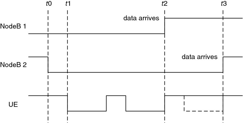
Figure 5.17 DRX with inter-site Multiflow with two independent DRX state machines in the NodeBs
5.9 Setting Up Multiflow
As mentioned earlier, from a specification perspective Multiflow can be understood as an extension of multicarrier HSDPA. Thus, setting up a Multiflow connection is similar to configuring a multicarrier radio bearer (RB): in addition to the typical RB information of carrier frequency, and other cell configurations, a few new information elements were added to the configuration.
In a typical sequence of events a UE would first carry out measurements and send reports on the strength of neighboring cells to the RNC. The RNC can – based on the measurement report and load information of the neighboring cells that it has available – identify which UEs would benefit from the Multiflow transmission. From there on, the RNC would proceed to perform radio link (re-)configurations of the involved NodeBs, as well as the UE. In particular the RNC will configure the NodeB with a “RL Addition” or “RL Reconfiguration” (or “RL Reconfiguration Prepare”) message, which carries the relevant parameters. The UE will be configured by the RNC as part of an active set update or as part of a separate RB (re-)configuration. A schematic overview of the sequence of steps is shown in Figure 5.18, a more detailed view on RL and RB reconfiguration signaling flows applicable also to Multiflow is shown for instance in [4] Figure 9.5-1.
Figure 5.18 Configuring Multiflow
The new parameters required to configure a UE are contained within the new information element “Multiflow configuration info” (see section 10.3.6.31a in [7]). Those additional Multiflow specific parameters are:
- Indication of the “cell group,” which is effectively an indication of whether the cell belongs to the serving or the assisting NodeB.
- Indication of which cell is a downlink time reference for the bundling of uplink feedback.
In inter-site Multiflow, the configuration sent by the RNC to a NodeB is not visible to the other NodeB. However, both NodeBs require some information, and the configuration messages were thus enhanced with following parameters (see section 9.2.2.170 in [8]):
- Indication on whether NodeB is a serving or assisting.
- Total number of cells of the overall Multiflow configuration.
- Indication of which cell is the downlink time reference for the bundling of uplink feedback. For the non-time reference cell, RNC also indicates the timing offset.
- Indication of whether at least one cell in the other NodeB is configured in MIMO mode. Once at least one cell in any NodeB is configured with MIMO, the whole HS-DPCCH format changes.
5.10 Robustness
5.10.1 Robustness for RRC Signaling
Multiflow data transmission can be applied to RLC acknowledged mode (AM) and RLC unacknowledged mode (UM). When illustrating the radio bearer to transport channel mapping for inter-site Multiflow in Figure 5.19 it becomes apparent that Multiflow can be applied not only to the user RBs, but also to signaling RBs (SRBs), which are mapped to either RLC-UM or RLC-AM (for a list of all SRBs see [7] section 6.3). The advantage of doing so lies in increasing the robustness of, for example, a serving cell change: a message for RB reconfiguration can be relayed not only over the one link, but also over the other if a first RLC transmission failed. For the highest robustness the reconfiguration message could be relayed over both links from the beginning. Thus, a reconfiguration message would not reach the UE only if both configured NodeBs have lost connectivity with the UE.
Figure 5.19 RB and SRB mapping onto logical and transport channels in Multiflow
5.10.2 Radio Link Failure
In the UE a radio link failure (RLF) is declared if synchronization to the serving cell is lost and the power control command carrying the F-DPCH signal level from the serving HS-DSCH cell falls below a fixed threshold for a given time duration, see [9] section 4.3.1.2. RLF leads to the UE falling back to CELL_FACH, from which it can be configured back to the CELL_DCH state. In Multiflow RLF behavior remains unchanged. However, the network is able to initiate reconfiguration steps before the UE RLF timer expires if one of the Multiflow links can still be received by the UE, increasing robustness also for these somewhat rare events.
5.10.3 Robustness for User Plane Data
The ability to send data in downlink from two sites is not only beneficial for the robustness of SRBs, but also for time-critical user plane data, such as voice packets when using either VoIP mapped on HSPA or CS voice over HSPA (CSoHS). In the case of a UE moving across cell borders, the voice data can be bicasted instead of being split at the RNC, and hence there will be always at least one link providing the data. The RLC layer would then remove the duplicated RLC PDUs (if received correctly over two radio links). As mentioned in Section 5.6.2, RNC can also bicast RLC STATUS PDUs for the uplink traffic received from the UE.
5.11 Multiflow Performance
5.11.1 Multiflow Performance in Macro Networks
The HSDPA Multiflow provides clear improvements for cell edge users, especially when the system loading is not uniform. When a cell is less loaded, the use of Multiflow allows “borrowing” capacity from the neighboring cell to the more loaded cell(s). When the system load starts to increase, then the additional system capacity effect is reduced, but for individual users there is still benefit from the increased cell edge performance, even if the full system capacity does not necessarily improve that much. Thus, even if the system capacity at high load remains mostly unchanged, the use of Multiflow basically allows one to trade the total system capacity with the cell edge user performance.
The improvements for the cell edge UEs are shown in Figure 5.20, indicating the dependency of the performance improvement and the actual cell load. Depending on the network parameterization, the benefit for the cell edge UEs may be between 25 and 50% of all UEs in the network.

Figure 5.20 Performance of Multiflow
The impact to the burst rate (median) is shown in Figure 5.21, indicating approximately 35% increase to the average burst rate for the soft or softer handover users when using Multiflow.
Figure 5.21 Median burst rate improvement with Multiflow
The performance results demonstrate that the HSDPA Multiflow can bring a real impact to the cell edge performance of HSDPA networks, reaching 35% gain or even higher in partially loaded networks where some of the cells have lower load than others.
5.11.2 Multiflow Performance with HetNets
In HetNets, where small cells are deployed within macro cells on the same frequency layer, the amount of UEs at the cell edge is larger, and the load imbalances between cells are greater, as the small cells are placed in hotspots where user concentrations are elevated. This leads to higher Multiflow gains in HetNets than in the macro only scenario.
If small cells are deployed on their own frequency layer, then there is no co-channel interference and the gains for Multiflow with HetNet will be even greater. Some of those scenarios require, however, that the NodeBs are able to receive the uplink of the UE on a frequency which is not paired to their downlink carrier. Even more importantly, it remains to be seen whether operators will reserve a dedicated carrier for small cells only, rather than configure macro stations as multicarrier cells.
A more detailed account of gains in Multiflow with HetNets is provided in Chapter 7.
5.12 Multiflow and Other Multipoint Transmission Techniques
The feature most similar to Multiflow is, as mentioned earlier, LTE dual connectivity, which is planned for 3GPP Release 12. The similarity comes with the usage of independent schedulers and a data flow split across two sites, and that transmissions can occur on different carriers. The LTE Release 11 interference coordination scheme, feICIC, is benefitting specifically cell edge users just as Multiflow does.
LTE CoMP – coordinated multipoint transmission/reception – has some similarity with Multiflow, in that several nodes may transmit to one receiver. LTE CoMP comprises a number of schemes, ranging from dynamic coordinated transmission point selection to coordinated joint transmission from up to three sites. The gains for CoMP materialize from exploiting the large diversity of the channel as well as interference coordination. One of the prerequisites for LTE CoMP is a perfect backhaul that limits its practical use. Also the amount and the quality of the feedback available from the UE diminishes the gains that can be achieved in reality.
In a comparison with other multipoint and cell aggregation techniques, HSDPA Multiflow is positioned as a very low complexity technique without additional spectrum requirements, providing gains for low–medium loads. LTE CoMP, on the other hand, takes the place of maximal complexity with benefits also for high loads. An overview of the techniques and their requirements and gains is shown in Table 5.1.
Table 5.1 Overview of downlink multipoint and cell aggregation techniques
| Gain principle | Range of gain | Data flow | Inter-site network operation | Other network requirements | 3GPP Release | |
| WCDMA SHO | Diversity combining | Robustness diversity benefit | Same data | Symbol level synchronized transmission from two cells on individual PSC | Asynchronous network, SHO user-specific transmission however synchronized. Slightly increased backhaul traffic | R99 |
| HSDPA multicarrier, LTE carrier aggregation | Increased bandwidth, load balancing | Scales with bandwidth, see Chapter 3 | Independent data and schedulers | Not applicable | Same cell timing | Rel8-11 |
| HSDPA Multiflow | Cell aggregation, load balancing | Macro co-channel (same bandwidth) scenario: low–medium load: up to 50% for cell edge, 10% average gain | Independent data and schedulers | No NodeB–NodeB coordination requirement, data flow split in the RNC | Asynchronous network, no increase in backhaul traffic | Rel11 |
| LTE CoMP | Dynamic multisite coordination and MIMO (dynamic point selection, coordinated beamforming), up to three involved sites | Depending on mode and scenario, also for high loads: up to 30% for cell edge [10] | Depending on mode independent data, but coordinated transmission | Very demanding inter-site coordination requirements, however intra-site CoMP already provides most of the gains | Synchronized network, joint transmission mode requires centralized baseband | Rel11 |
| LTE feICIC | Interference coordination | HetNet co-channel scenario: up to 100% cell edge gains | Independent data but coordinated scheduling | HetNet feature: Coordination of transmit resources | Synchronous network | Rel11 |
| LTE dual connectivity | Cell aggregation, load balancing | HetNet inter-frequency scenario: low–medium load: up to 50% cell edge, 20% average gain with realistic backhaul | Independent data and schedulers | HetNet feature: data flow is split in RLC layer of macro eNB and forwarded to low power eNB. Independent schedulers | Increase in backhaul or X2 traffic because of data forwarding | Rel12 planned |
5.13 Conclusions
This chapter has introduced HSDPA Multiflow protocol and physical layer operation principles as well as demonstrated the achievable capacity benefits. As the impacts to the UE and network implementation are reasonable and resulting performance benefits accrue especially to the cell-edge users, it is foreseen that HSDPA Multiflow will be an attractive feature to be adopted in the marketplace.
As use of HSDPA Multiflow is fully backwards compatible, that is, it can be operated in a network with both Release 11 UEs and older ones, it can be rolled out gradually to the network to boost the cell edge performance.
The LTE-Advanced carrier aggregation [11] has some similarity with the HSDPA Multiflow, only that the Release 10 carrier aggregation is done as intra-site aggregation and only as part of the Release 12 small cell evolution studies [3] the inter-site operation is expected to be introduced as part of the dual connectivity in Release 12 specification, due by the end of 2014.
References
- 3GPP Technical Report, TR 25.872, “High Speed Packet Access (HSDPA) multipoint transmission”, Release 11, 2011.
- 3GPP Tdoc, RP-111375, WI description “HSDPA Multiflow data transmission”, 2011.
- 3GPP Technical Report, TR 36.842 “Study on small cell enhancements for E-UTRA and E-UTRAN - Higher-layer aspects”, Release 12, December 2013.
- 3GPP Technical Specification, TS 25.308, “HSDPA overall description”, Release 11. 11, March 2013.
- 3GPP Technical Specification, TS 25.212, “Multiplexing and channel coding (FDD)”, Release 11, March 2013.
- 3GPP Technical Specification, TS 25.213, “Spreading and Modulation (FDD), Release 11, March 2013.
- 3GPP Technical Specification, TS 25.331, “Radio resource control protocol specification”, Release 11, March 2013.
- 3GPP Technical Specification, TS 25.433, “UTRAN Iub interface Node B Application Part (NBAP) signalling”, Release 11, September 2013.
- 3GPP Technical Specification, TS 25.214, “Physical layer procedures (FDD)”, Release 11, March 2013.
- 3GPP Technical Report, TR 36.819, “Coordinated multi-point operation for LTE physical layer aspects”, Release 11, September 2013.
- Holma, H. and Toskala, A. (2012) LTE-Advanced, John Wiley & Sons, Ltd, Chichester.
- 3GPP Technical Specification, TS 25.211, “Physical channels and mapping of transport channels onto physical channels (FDD)”, Release 11, June 2013.