

Virtualization
This chapter describes the following topics:
7.1 PowerVM enhancements
The following sections summarize recent PowerVM enhancements for IBM i, and include the following topics:
7.1.1 Active memory sharing
Active memory sharing (AMS) enables the sharing of a pool of physical memory among IBM i, AIX, and SUSE Linux logical partitions on a single IBM Power Systems server POWER6 or later, helping to increase memory use and drive down system costs. The memory is dynamically allocated among the partitions as needed, to optimize the overall physical memory usage in the pool. Instead of assigning a dedicated amount of physical memory to each logical partition that uses shared memory (referred to as shared memory partitions), the hypervisor provides the physical memory from the shared memory pool to the shared memory partitions as needed. The Power hypervisor provides portions of the shared memory pool that are not being used by shared memory partitions to other shared memory partitions that must use the memory.
When a shared memory partition needs more memory than the current amount of unused memory in the shared memory pool, the hypervisor stores a portion of the memory that belongs to the shared memory partition in an auxiliary storage space that is known as a paging space device. Access to the paging space device is provided by a Virtual I/O Server (VIOS) logical partition that is known as the paging service partition. When the operating system of a shared memory partition accesses data that is in a paging space device, the hypervisor directs the paging service partition to retrieve the data from the paging space device. The partition then writes it to the shared memory pool so that the operating system can access the data.
For an illustration of these AMS concepts, see Figure 7-1.
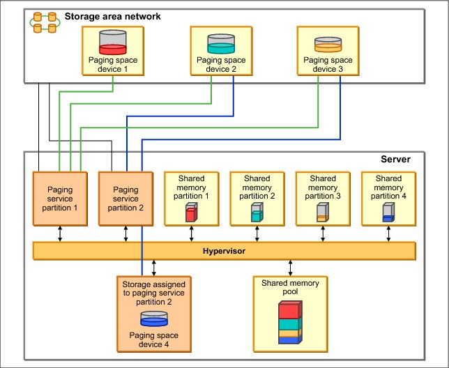
Figure 7-1 AMS concepts
The PowerVM Active Memory Sharing technology is available with the PowerVM Enterprise Edition hardware feature, which also includes the license for the VIOS software.
Paging service partitions must be VIOS. Logical partitions that provide virtual I/O resources to other logical partitions can be VIOS or IBM i. They must be dedicated memory partitions, but their client partitions are shared memory partitions.
|
Important: Logical partitions that have dedicated physical resources cannot be shared memory partitions.
|
In general terms, the setup of AMS includes using the HMC to create a shared memory pool, selecting a paging service partition, selecting a paging space device, and changing the IBM i client partition profile to use shared memory pool. See Figure 7-2.
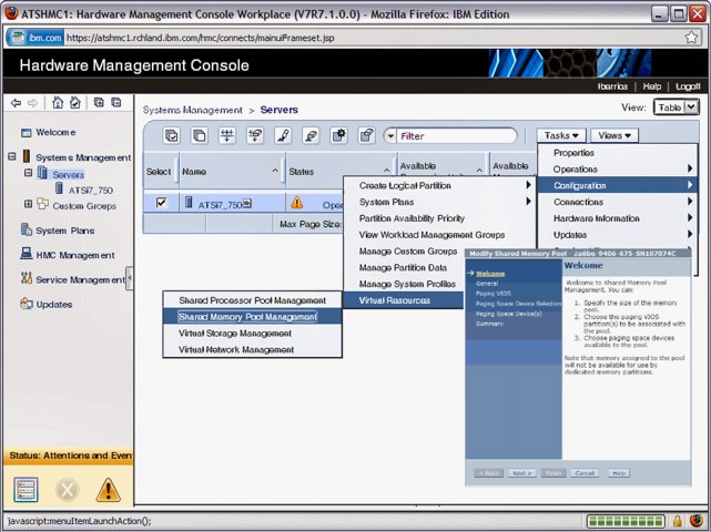
Figure 7-2 AMS setup using the HMC
You can configure two paging service partitions to access the same, or common, paging space devices. In this configuration, the two paging service partitions provide redundant access to the paging space devices (see Figure 7-3). This function is known as redundant paging service partitions. When one paging service partition becomes unavailable, the hypervisor sends a request to the other paging service partition to retrieve the data on the paging space device. For more information about redundant VIOS partitions support, see 7.1.8, “Redundant VIOS partitions support” on page 330.

Figure 7-3 Redundant paging service partitions
For IBM i client partitions where the disk storage is virtualized using VIOS partitions and storage area network (SAN) Disk Storage, NPIV and multipath I/O support is available with IBM i 6.1.1 or later. For more information about NPIV, see 7.1.3, “PowerVM Virtualization and I/O enhanced with NPIV” on page 326. For multipath I/O for IBM i client partitions, see 8.3.2, “Multipathing for virtual I/O” on page 400.
|
Requirement: When you use redundant paging service partitions, common paging space devices must be on SAN Disk Storage to enable symmetrical access from both paging service partitions.
|
The system requirements for AMS are as follows:
•IBM Power Systems server or blade with POWER6 processors
•Virtual I/O Server (VIOS) 2.1.0.1 Fix Pack 21 or later
•System Firmware level 340_075 or later
•HMC V7.342 or later
•IBM i 6.1 plus PTF SI32798 or later
•AIX V6.1 TL3
•SUSE Linux Enterprise Server 11
|
Solid-state disk usage: A solid-state disk (SSD) on VIOS can be used as a shared memory pool paging space device. For more information, see 8.4, “SSD storage management enhancements” on page 411.
|
For an overview of AMS, go to:
For more detailed information about AMS, see IBM PowerVM Virtualization Active Memory Sharing, REDP-4470.
7.1.2 Enhanced support for IBM system storage
Over the past few years, IBM has announced additional connectivity methods for IBM i to use various types of external storage. As these methods and supported devices are constantly changing and expanding, check online resources for the latest compatibility and support statements as provided by IBM.
A significant enhancement for IBM i 7.1 includes connectivity to the IBM Storwize Family and SAN Volume Controller as shown in Figure 7-4.
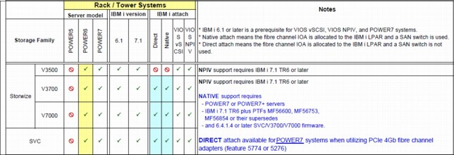
Figure 7-4 New enhancements available for IBM i connectivity to Storwize and SAN Volume Controller
A summarization of connectivity methods and supported devices is shown in Figure 7-5.
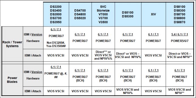
Figure 7-5 Supported IBM i and external storage combinations
For more information about storage area networks and IBM i, see Chapter 8, “Storage and solid-state drives” on page 377.
|
Support availability: NPIV support has been expanded in IBM i 7.1. For more information about NPIV, see 7.1.3, “PowerVM Virtualization and I/O enhanced with NPIV” on page 326.
|
For an overview of IBM i System Storage solutions, see IBM i Virtualization and Open Storage read-me first, found at:
For more information about available SAN Storage solutions for Power Systems and IBM i, see the System Storage Interoperation Center at:
For more information about IBM i and supported connectivity methods to various types of IBM external storage, see the IBM System Storage Interoperation Center (SSIC) at:
7.1.3 PowerVM Virtualization and I/O enhanced with NPIV
N_Port ID Virtualization (NPIV) is an industry-standard Fibre Channel (FC) protocol that allows the VIOS to share an NPIV-capable FC adapter among multiple client partitions. For NPIV, the VIOS server acts as an FC pass-through instead of a SCSI emulator, such as when you use Virtual SCSI (see Figure 7-6).
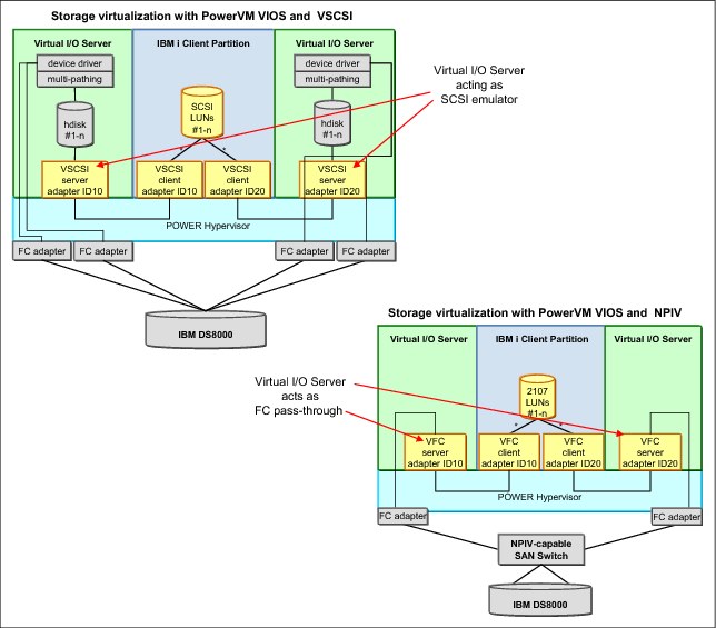
Figure 7-6 Comparing PowerVM storage virtualization with VSCSI and NPIV
With NPIV, a port on the physical FC adapter is mapped to a Virtual Fibre Channel (VFC) server adapter in VIOS, which in turn is mapped to a VFC client adapter in the IBM i client partition, as shown in Figure 7-7.

Figure 7-7 VIOS VFC server adapter and IBM i VFC client adapter
Two unique worldwide port names (WWPNs) are generated for the VFC client adapter, which is available on the SAN so that storage can be mapped to them as you can to any other FC ports. The following issues must be considered when you use NPIV:
•There is one VFC client adapter per physical port per partition, to avoid a single point of failure.
•A maximum of 64 active VFC client adapters are permitted per physical port. This number can be less because of other VIOS resource constraints.
•There can be only 32,000 unique WWPN pairs per system platform.
– Removing an adapter does not reclaim WWPNs. Can be manually reclaimed through the CLI (mksyscfg, chhwres, and so on) or through the “virtual_fc_adapters” attribute.
– If the capacity is exhausted, you must purchase an activation code for more capacity.
|
Important: Only one of the two WWPN ports is used (port 0). The second WWPN port is not used.
|
IBM i 6.1.1 supports NPIV, providing direct Fibre Channel connections from i 6.1.1 client partitions to SAN resources. The IBM i clients see the SAN resources with their native device type as though they were natively attached (see Figure 7-8).
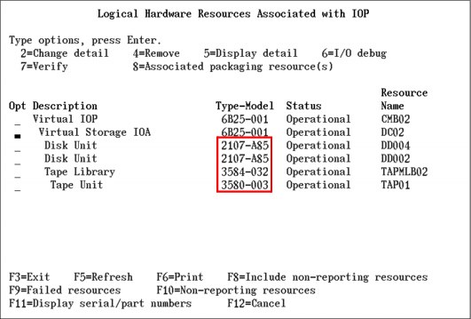
Figure 7-8 SAN resources as seen by IBM i client partitions when you use NPIV
The 6B25-001 shows a single port (0). The worldwide port name is how the SAN recognizes the Virtual IOA, as shown in Figure 7-9.

Figure 7-9 Virtual Storage IOA 6B25-001 details
The following are supported tape and tape media library devices and their requirements when attaching them using NPIV:
•3573 (TS3100/TS3200) with LTO3, LTO4, LTO5, and LTO6 tape drives
•3576 (TS3310) with LTO3, LTO4, LTO5, and LTO6 tape drives
•3577 (TS3400) with TS1120 and TS1130 tape drives
•3584 (TS3500) with LTO3, LTO4, LTO5, LTO6, TS1120, TS1130, TS1140, and 3592-J1A tape drives
•TS7610 (ProtecTIER) with software version v2.1 or later
•TS7620 (ProtecTIER) with software version v2.1 or later
•TS7650 (ProtecTIER) with software version v2.4 or later
•TS1130 and TS1140 stand-alone drives
•FC 8248 HH-LTO5 FC in 7226 enclosure (IBM Flex systems only)
•FC 8348 HH-LTO6 FC in 7226 enclosure
LTO6 support in IBM i 7.1 requires PTFS MF55886 and MF55967, and if using BRMS, SI47039 or its superseding PTF.
|
Note: The devices cannot be directly attached. They must be attached through an NPIV-capable switch. Plan for a performance degradation of about 10% or more for devices that are attached using NPIV compared to the same devices attached in a native IOP-less configuration.
|
7.1.4 Expanded HBA and switch support for NPIV on Power Blades
Power Blades running PowerVM VIOS 2.2.0 with IBM i 7.1 partitions support the QLogic 8 Gb Blade HBAs to attach DS8100, DS8300, and DS8700 storage systems through NPIV. This support allows easy migration from existing DS8100, DS8300, and DS8700 storage to a blade environment. Full PowerHA support is also available with virtual Fibre Channel and the DS8100, DS8300, and DS8700, which includes Metro Mirroring, Global Mirroring, FlashCopy, and LUN level switching.
7.1.5 PowerVM N_Port ID Virtualization attachment of DS5000 and Storwize
IBM i 7.1 partitions on POWER6 or POWER7 rack and tower systems now support N_Port ID Virtualization attachment of DS5100 and DS5300 storage systems, as well as IBM Storwize Family systems. Setting up configurations to share adapters is simpler with NPIV. This support also allows the usage of a Lab Services toolkit to access copy services for the storage.
For compatibility information, consult the Storage Systems Interoperability Center at:
7.1.6 Enhanced mirroring algorithms
IBM i mirroring algorithms are enhanced to consider any N_Port ID Virtualization (NPIV) attached disks. The locations of the virtual disks are considered when the pairs of mirror disk units are calculated bus level statistics for 12x loops.
7.1.7 PCIe2 Riser Card (Gen2) (#5685) direct support
IBM i now provides direct support for the PCIe Riser Card (Gen2), without the use of VIOS, with IBM i 7.1. This riser card is used in the IBM Power 720 and IBM Power 740 Express to provide greater bandwidth with a smaller number of PCI slots or adapters. It is an optional feature, containing four PCIe Gen2 low-profile (LP) slots for Gen1 or Gen2 adapters. It is physically similar to the PCIe Riser Card (Gen1) (#5610).
For more information about N_Port ID Virtualization (NPIV) for IBM i, see the IBM i Virtualization and Open Storage read-me first topic, found at:
For more information about SAN Storage solutions for Power Systems and IBM i, see the System Storage Interoperation Center at:
7.1.8 Redundant VIOS partitions support
For enhanced availability in a PowerVM VIOS environment, IBM i 6.1.1 or later client partitions can be configured in multipath configurations where one partition uses redundant VIOS partitions to connect to the same IBM System Storage device, as shown in Figure 7-10.
|
Important: Redundant VIOS support is available on POWER6 or later processor-based servers. It is not supported by BladeCenter and Power Blades.
|
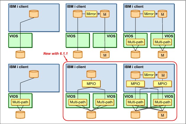
Figure 7-10 Redundant VIOS using VSCSI
IBM i 6.1.1 or later IBM i clients support Redundant VIOS partitions and N_Port ID Virtualization (NPIV) for attachment to IBM System Storage DS8000 solutions, as shown in Figure 7-11.

Figure 7-11 Redundant VIOS partitions using NPIV
For more information about Redundant VIOS partitions, see the IBM i Virtualization and Open Storage read-me first topic, found at:
7.1.9 Shared storage pools
Shared storage pools are a new capability that is available with Virtual I/O Server Version 2.2.0.11, Fix Pack 24, Service Pack 1. Shared storage pools provide the following benefits:
•Simplifies the aggregation of many disks across multiple Virtual I/O Servers.
•Improves the usage of the available storage.
•Simplifies administration tasks.
Shared storage pool architecture overview
A shared storage pool is a pool of SAN storage devices that can span multiple Virtual I/O Servers. It is based on a cluster of Virtual I/O Servers and a distributed data object repository with a global namespace. Each Virtual I/O Server that is part of a cluster represents a cluster node.
When you use shared storage pools, the Virtual I/O Server provides storage through logical units that are assigned to client partitions. A logical unit is a file backed storage device that is in the cluster file system in the shared storage pool. It appears as a virtual SCSI disk in the client partition, in the same way as a, for example, virtual SCSI device that is backed by a physical disk or a logical volume.
Prerequisites
A shared storage pool requires the following prerequisites:
•POWER6 (and later) based servers (including blades).
•PowerVM Standard Edition or PowerVM Enterprise Edition.
•Virtual I/O Server requirements:
– Version 2.2.0.11, Fix Pack 24, Service Pack 1, or later.
– Processor entitlement of at least one physical processor.
– At least 4 GB memory.
•Client partition operating system requirements:
– IBM AIX 5L™ V5.3 or later.
– IBM i 6.1.1 or later with the latest PTF.
•Local or DNS TCP/IP name resolution for all Virtual I/O Servers in the cluster.
•Minimum storage requirements for the shared storage pool:
– One Fibre Channel attached disk that acts as a repository, with at least 20 GB of disk space.
– At least one Fibre Channel attached disk for shared storage pool data. Each disk must have at least 20 GB of disk space.
•All physical volumes for the repository and the shared storage pool must have redundancy at the storage level.
Virtual I/O Server storage clustering model
The Virtual I/O Servers that are part of the shared storage pool are joined to form a cluster. A Virtual I/O Server that is part of a cluster is also referred to as cluster node. Only Virtual I/O Server partitions can be part of a cluster.
The Virtual I/O Server clustering model is based on Cluster Aware AIX (CAA) and RSCT technology. The cluster for the shared storage pool is an RSCT Peer Domain cluster. Therefore, a network connection is needed between all the Virtual I/O servers that are part of the shared storage pool.
Each Virtual I/O Server in the cluster requires at least one physical volume for the repository that is used by the CAA sub system and one or more physical volumes for the storage pool.
All cluster nodes in a cluster can see all the disks. Therefore, the disks must be zoned to all the cluster nodes that are part of the shared storage pools. All nodes can read and write to the shared storage pool. The cluster uses a distributed lock manager to manage access to the storage.
The Virtual I/O Servers in the cluster communicate with each other using Ethernet connections. They share the repository disk and the disks for the storage pool through the SAN.
For an abstract image of a shared storage pool, see Figure 7-12.
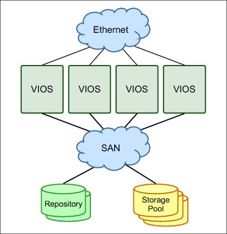
Figure 7-12 Abstract image of the clustered Virtual I/O Servers
Shared storage pool layout
The shared storage pool manages logical units as a file. Portions of the logical unit are cached on the client node in a cluster. The logical unit consists of virtual blocks and has a virtual block address space.
The physical volumes in the shared storage pool are managed as an aggregation of physical blocks and user data is stored in these blocks. These physical blocks are managed by a metadata area on the physical volumes. Therefore, the physical volumes in the shared storage pool consist of physical blocks and have a physical block address space.
The translation from a virtual block address to a physical block address is done by the Virtual Address Translation Lookaside (VATL).
The system reserves a small amount of each physical volume in the shared storage pool to record metadata. The remainder of the shared storage pool capacity is available for client partition user data. Therefore, not all of the space of physical volumes in the shared storage pool can be used for user data.
Thin provisioning
A thin-provisioned device represents a larger image than the actual physical disk space it is using. It is not fully backed by physical storage if the blocks are not in use.
A thin-provisioned logical unit is defined with a user-specified size when it is created. It appears in the client partition as a virtual SCSI disk with that user-specified size. However, on a thin-provisioned logical unit, blocks on the physical disks in the shared storage pool are allocated only when they are used.
Compared to a traditional storage device, which allocates all the disk space when the device is created, this situation can result in significant savings in physical disk space. It also allows overcommitting of the physical disk space.
For an overview of thin provisioning of a shared storage pool, see Figure 7-13.

Figure 7-13 Thin-provisioned devices in the shared storage pool
7.1.10 More partitions per core
POWER7+ processor-based systems can run up to 20 partitions per core (.05 core per LPAR) versus the previous limitation of 10 (.10 core per LPAR).
7.1.11 Virtualization of USB-attached storage for IBM i
See 8.1.18, “VIOS support for RDX USB docking station for removable disk cartridge” on page 395 for a more detailed description of this enhancement.
7.2 More OS level combinations of server and client logical partitions
IBM PowerVM continues to enable Power Systems with IBM i to achieve higher resource usage by supporting more OS level combinations of server and client logical partitions, as shown in Figure 7-14.
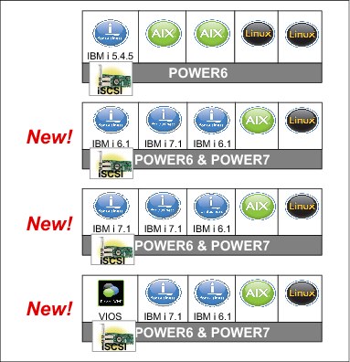
Figure 7-14 OS level combinations of server and client for IBM i and VIOS
•IBM i 6.1 server partition can provide virtual I/O resources to the following elements:
– IBM i 6.1 and 7.1 or later client partitions
– AIX V5.2, V5.3, and V6.1, and SLES and Red Hat Linux client partitions
– iSCSI-attached IBM System x and BladeCenter
•IBM i 7.1 server partition can provide virtual I/O resources to the following elements:
– IBM i 6.1 and 7.1 or later client partitions
– AIX V5.2, V5.3, and V6.1, and SLES and Red Hat Linux client partitions
– iSCSI attached System x and BladeCenter
•PowerVM VIOS 2.1.3 server partition can provide virtual I/O resources to the following elements:
– IBM i 6.1 and 7.1 or later client partitions
– AIX and Linux client partitions
The following list describes the benefits of using IBM i hosting IBM i:
•Uses the same technology as IBM i hosting AIX, Linux, and iSCSI x86 servers.
•Uses the existing hardware investment. You can create new IBM i partitions using only virtual hardware (no IOAs, IOPs, disk units, or I/O slots are necessary for client partitions), but you can also use physical I/O.
•Rapidly deploy new workloads.
– You can create a virtual disk with one command or several clicks in IBM Navigator for i.
– You can deploy new partitions and virtual resources dynamically.
– You can create test environments without hardware provisioning.
– Virtual resources allow new test environments of exact sizes to be created and deleted without moving hardware.
– You can test new applications, tools, and fixes in a virtual test partition.
– You can test the next release in the client partition.
For more information about PowerVM, see IBM PowerVM Virtualization Introduction and Configuration, SG24-7940.
For more information about IBM i client partitions, see the IBM i Knowledge Center at:
7.3 Hardware Management Console virtual device information
Virtual device information is now available on the Hardware Management Console (HMC) for VIOS logical partitions. The HMC can now display a list of the virtual SCSI adapters for a VIOS logical partition, as shown in Figure 7-15.

Figure 7-15 Virtual Device Information in the HMC
|
Tip: To access the Virtual Device Information in the HMC, click Server → Partitions → VIOS partition → Hardware Information → Virtual I/O Adapters → SCSI.
|
The following list describes the information that is displayed in the HMC:
•Virtual Adapter
This column displays the name of each virtual server SCSI adapter.
•Backing Device
This column displays the name of the storage device whose storage capacity can be used through a virtual SCSI connection to this virtual server SCSI adapter. This storage device is on the same logical partition as the virtual server SCSI adapter.
•Remote Partition
This column displays the partition name and partition ID (in parentheses) of the logical partition to which each virtual server SCSI adapter is set to connect. If this column is blank, then the virtual server SCSI adapter is set to connect to any logical partition.
•Remote Adapter
This column displays the virtual slot ID of the virtual client SCSI adapter to which each virtual server SCSI adapter is set to connect. If this column contains none, then the virtual server SCSI adapter is set to connect to any virtual client SCSI adapter.
•Remote Backing Device
This column displays the name of the virtual disks (or logical volumes) that display on the logical partition with the virtual client SCSI adapter when a virtual SCSI connection exists. The logical partition with the virtual client SCSI adapter can use these virtual disks to store information about the storage device that is owned by the logical partition with the virtual server SCSI adapter. This column contains a value only if the virtual server SCSI adapter is connected to a virtual client SCSI adapter.
|
Consideration: You can create virtual server SCSI adapters only for Virtual I/O Server and IBM i logical partitions. This window is always blank for AIX and Linux logical partitions.
|
The following list details the requirements for virtual device information:
•POWER6 or later rack / tower systems
•BladeCenter H
•System firmware level 350_038 or later
•HMC V7.3.5 or later
•VIOS V2.1.2 (FP 22.1) or later
•IBM i 6.1.1 or later (+latest fixes)
Similar information is available by running lshwres on the HMC or Integrated Virtualization Manager (IVM) by using the new attribute topology on the -F flag.
Example 7-1 lists the Virtual SCSI Adapter attributes in the form of a slash delimited list.
Example 7-1 List Virtual SCSI Adapter attributes
#Command:
lshwres -m <system name> -r virtualio --rsubtype scsi --level lpar -F lpar_name,remote_lpar_name,topology
#Results:
za6bp10,za6bvios2,"OPT01/Active/DC01/vhost6//""/var/vio/VMLibrary/slic611190004AMSTAPE.iso"",TAP01/Active/DC01/vhost6//rmt1"
za6bp11,za6bvios2,"OPT01/Active/DC01/vhost9//""/var/vio/VMLibrary/slic611190004AMSTAPE.iso"""
za6bp12,za6bvios2,"OPT01/Active/DC01/vhost10//""/var/vio/VMLibrary/slic611190004AMSTAPE.iso"",DPH001/Active/DC01/vhost10//hdisk28"
za6bp15,za6bvios2,"OPT01/Active/DC01/vhost0//""/var/vio/VMLibrary/WindowsServer2003.iso"",DD006/Active/DC01/vhost0//hdisk29,DD001/Missing/DC01/vhost0//hdisk29"
za6bvios,za6bp4,///vhost0//hdisk2
za6bvios,za6bp4,///vhost1//hdisk3
za6bvios2,za6bp6,"///vhost3//""/var/vio/VMLibrary/xpf710_370_B292403.iso"""
za6bvios2,za6bp13,"///vhost4//,///vhost4//hdisk36
Example 7-2 lists the Virtual Fibre Channel Adapters attributes for each logical partition in the form of a slash delimited list.
Example 7-2 Virtual Fibre Channel Adapters attributes
#Command:
lshwres -m <system name> -r virtualio --rsubtype fc --level lpar -F lpar_name,remote_lpar_name,topology
#Results:
za6bp10,za6bvios3,/Active/DC04/vfchost7/fcs0
za6bp10,za6bvios2,"/Active/DC03/vfchost4/fcs4,DD002/Missing/DC03/vfchost4/fcs4"
za6bp10,za6bvios3,"/Active/DC02/vfchost0/fcs1,DD001/Active/DC02/vfchost0/fcs1"
za6bp11,za6bvios2,"/Active/DC03/vfchost7/fcs4,DD001/Active/DC03/vfchost7/fcs4"
za6bp11,za6bvios3,/Active/DC02/vfchost2/fcs1
za6bp12,za6bvios2,"/Active/DC03/vfchost8/fcs4,DD001/Active/DC03/vfchost8/fcs4,DD003/Active/DC03/vfchost8/fcs4"
za6bp12,za6bvios3,/Active/DC02/vfchost4/fcs1
za6bp13,za6bvios2,unavailable
za6bp13,za6bvios2,unavailable
za6bp15,za6bvios2,"/Active/DC02/vfchost1/fcs3,DD002/Active/DC02/vfchost1/fcs3,DD007/Active/DC02/vfchost1/fcs3"
za6bvios2,za6bp13,///vfchost5/fcs3
za6bvios2,za6bp10,///vfchost4/fcs4
za6bvios2,za6bp6,///vfchost3/fcs3
za6bvios2,za6bp18,///vfchost2/fcs3
za6bvios2,za6bp13,///vfchost13/fcs4
Example 7-3 lists the Virtual Ethernet Adapter attributes.
Example 7-3 Virtual Ethernet Adapter attributes
#Command:
lshwres -m <system name> -r virtualio --rsubtype eth --level lpar -F lpar_name,connect_status,device_name,drc_name,shared_adapter,backing_device
#Results:
za6bp10,active,CMN01,U9406.675.107074C-V10-C2-T1,,
za6bp10,none,CMN02,U9406.675.107074C-V10-C3-T1,,
za6bp12,active,CMN01,U9406.675.107074C-V12-C2-T1,,
za6bp12,active,CMN02,U9406.675.107074C-V12-C3-T1,,
za6bp15,active,CMN03,U9406.675.107074C-V15-C2-T1,,
za6bp15,active,CMN04,U9406.675.107074C-V15-C3-T1,,
za6bvios,active,ent2,U9406.675.107074C-V16-C11-T1,ent4,ent0
za6bvios,active,ent3,U9406.675.107074C-V16-C12-T1,,
za6bvios2,active,ent2,U9406.675.107074C-V17-C11-T1,ent4,ent0
For more information about the lshwres command, go to the Hardware Knowledge Center at:
7.4 IBM i hosting IBM i - iVirtualization
An IBM i 6.1 or 7.1 partition can host one or more IBM i partitions, which are known as virtual client partitions. Virtual client partitions typically have no physical I/O hardware that is assigned and instead use virtual I/O resources from the host IBM i partition. The types of hardware resources that can be virtualized by the host partition are disk, tape, optical, and networking. The capability of IBM i to provide virtual I/O resources was used successfully for several years to integrate AIX, Linux, and Microsoft Windows workloads on the same platform. The same virtualization technology, which is part of the IBM i operating system, can now be used to host IBM i partitions, as shown in Figure 7-16.

Figure 7-16 IBM i hosting IBM i components
IBM i hosting IBM i (iVirtualization) uses an existing function of the system firmware, or IBM Power Hypervisor, which can create VSCSI and Ethernet adapters in a partition.
|
iVirtualization: The term now being used for describing the hosting of IBM i client partitions with IBM i serving as the host is iVirtualization. The term might be used interchangeably with the phrase “IBM i hosting IBM i” in documentation and websites. It is important to note that iVirtualization is not the same as IBM i with its storage hosted from VIOS.
|
Virtual adapters are created for each partition in the Hardware Management Console (HMC) or virtual server in the Systems Director Management Console (SDMC). VSCSI adapters are used for storage and optical virtualization, virtual Ethernet adapters are used for network virtualization.
POWER6 or later and IBM i 6.1 or later is required to support IBM i client partitions.
|
Tip: VIOS server partitions can also virtualize a natively attached storage device to IBM i 6.1 or later client partitions. For more information, see IBM PowerVM Virtualization Managing and Monitoring, SG24-7590.
|
7.4.1 Disk virtualization
To virtualize integrated disks (SCSI, SAS, or SSD) or LUNs from a SAN system to an IBM i client partition or virtual server, both HMC/SDMC and IBM i objects must be created:
•One VSCSI server adapter on the host partition
•One VSCSI client adapter on the client partition
This VSCSI adapter pair allows the client partition to send read and write I/O operations to the host partition. More than one VSCSI pair can exist for the same client partition in this environment. To minimize the performance impact on the host partition, the VSCSI connection is used to send I/O requests, but not for the actual transfer of data. Using the capability of the POWER Hypervisor for Logical Remote Direct Memory Access (LRDMA), data is transferred directly from the physical adapter that is assigned to the host partition to a buffer in memory of the client partition.
To create Virtual SCSI adapters for the IBM i host partition and IBM i client partition, complete the following steps:
1. Use the managing HMC to create a VSCSI server adapter on the IBM i host partition:
a. In the navigation pane, click Systems Management → Servers, and click the managed system on which the server IBM i host partition is.
b. Select the IBM i host partition, click Tasks, and click Dynamic Logical Partitioning → Virtual Adapters.
c. Click Actions and click Create → SCSI Adapter.
d. Use the default VSCSI Adapter number or provide your own number. Write down the VSCSI Adapter number, as you need it in a later step.
In Figure 7-17, the number 31 was provided as the Virtual SCSI Adapter number. In the Type of adapter field, select Server, and click OK.
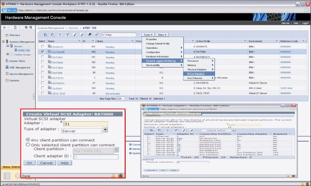
Figure 7-17 Create VSCSI Server Adapter
e. Save the current configuration for the IBM i host partition so that the VSCSI adapter continues to exist after you restart the partition.
2. Create the VSCSI client adapter in the IBM i client partition, as shown in Figure 7-18 on page 343:
a. In the navigation pane, click Systems Management → Servers, and click the managed system on which the IBM i client logical partition is.
b. Select the IBM i client partition, click Tasks, and select Dynamic Logical Partitioning → Virtual Adapters.
c. Click Actions and select Create → SCSI Adapter.
d. Use the default VSCSI adapter number or provide your own number. In this example, the number 31 was provided as this number. In the Type of adapter field, select Client.
e. Select the IBM i server partition that provides the virtualized optical device as the server partition and specify the Server adapter ID from step 1d on page 341, as shown in Figure 7-18, where 31 was used. Click OK.
f. Create the VSCSI adapter within the partition profile for the IBM i client partition so that the VSCSI adapter continues to exist after you restart the partition.
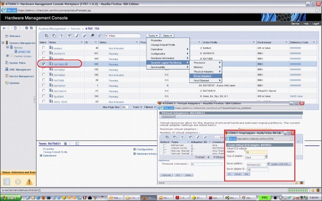
Figure 7-18 Create VSCSI client adapter
No additional configuration is required in IBM i in the virtual client partition. In the host partition, the minimum required IBM i setup consists of the following requirements:
•One network server description (NWSD) object
•One network server storage space (NWSSTG) object
The NWSD object associates a VSCSI server adapter in IBM i (which in turn is connected to a VSCSI client adapter in the HMC/SDMC) with one or more NWSSTG objects. At least one NWSD object must be created on the host for each client, although more are supported. The NWSSTG objects are the virtual disks that are provided to the client IBM i partition. They are created from available physical storage on the host partition. In the client, they are recognized and managed as standard DDxx disk devices (with a different type and model). The IBM i commands WRKNWSSTG and CRTNWSSTG can be used to manage or create Network Server Storage Space.
To link an NWSD object with an NWS storage space, complete the following steps:
1. Create a network server description (NWSD). On the IBM i host partition, enter CRTNWSD to create a network server description, and press F4 for prompts, then F9 to display all parameters.
Enter the following values:
Network Server Description Provide a name. CLIENT31 was used in the example in Figure 7-18 on page 343, which corresponds to the name of the IBM i client partition in this example.
Resource Name Provide the resource name. CTL05 was used in this example.
Network server type *GUEST.
Server operating system *OPSYS.
Online at IPL *YES.
Partition Specify IBM i client partition’s name.
Partition number Specify IBM i client partition number.
The partition and partition number cannot both be specified.
Code page 437.
Restricted service resources Use *NONE for an NWSD that all optical and tape device resources can use by client partition.
Power Control Use *NO if the NWSD is only for virtualizing an optical device. Use *Yes if the NWSD is also used to provide virtual disk storage.
Run the command of Create Network Server Desc (CRTNWSD), as shown in Figure 7-19.
|
Create Network Server Desc (CRTNWSD)
Type choices, press Enter.
Network server description . . . NWSD > ITSOP2
Resource name . . . . . . . . . RSRCNAME > CTL05
Network server type: TYPE
Server connection . . . . . . > *GUEST
Server operating system . . . > *OPSYS
Storage path: STGPTH
Network server host adapter .
IP security rules:
Remote interface 1 rule . . . *DFTSECRULE
Remote interface 2 rule . . . *DFTSECRULE
Remote interface 3 rule . . . *DFTSECRULE
Remote interface 4 rule . . . *DFTSECRULE
+ for more values
Default IP security rule . . . . DFTSECRULE *NONE
Multi-path group . . . . . . . . MLTPTHGRP *NONE
+ for more values
|
Figure 7-19 Specify NWSD name, resource, server type, and OS
2. Create an NWS Storage Space in the IBM i host partition by running the Create NWS Storage Space (CRTNWSSTG) command, as shown in Figure 7-20.
|
Create NWS Storage Space (CRTNWSSTG)
Type choices, press Enter.
Network server storage space . . NWSSTG > ITSOP1
Size . . . . . . . . . . . . . . NWSSIZE > 50000
From storage space . . . . . . . FROMNWSSTG *NONE
Format . . . . . . . . . . . . . FORMAT > *OPEN
Data offset . . . . . . . . . . OFFSET *FORMAT
Auxiliary storage pool ID . . . ASP 1
ASP device . . . . . . . . . . . ASPDEV
Text 'description' . . . . . . . TEXT *BLANK
|
Figure 7-20 Create an NWS Storage Space
3. Link the NWSD and NWS storage space. The new NWS storage space cannot be used until it has a link to NWSD. Run the Add Server Storage Link (ADDNWSSTGL) command, as shown in Figure 7-21.
|
Add Server Storage Link (ADDNWSSTGL)
Type choices, press Enter.
Network server storage space . . NWSSTG > ITSOSTG1
Network server description . . . NWSD > ITSOP1
Dynamic storage link . . . . . . DYNAMIC *NO
Network server type . . . . . . TYPE *NWSD
Access . . . . . . . . . . . . . ACCESS *UPDATE
Drive sequence number . . . . . DRVSEQNBR *CALC
Storage path number . . . . . . STGPTHNBR *DFTSTGPTH
|
Figure 7-21 Add Server Storage Link
Storage spaces for an IBM i client partition do not have to match physical disk sizes; they can be created from 160 MB - 1 TB, if there is available storage on the host. The 160 MB minimum size is a requirement from the storage management Licensed Internal Code (LIC) on the client partition. For an IBM i client partition, up to 16 NWSSTGs can be linked to a single NWSD, and therefore to a single VSCSI connection. Up to 32 outstanding I/O operations from the client to each storage space are supported for IBM i clients. Storage spaces can be created in any existing auxiliary storage pool (ASP) on the host, including Independent ASPs. Through the usage of NWSSTGs, any physical storage that is supported in the IBM i host partition on a POWER6 based system can be virtualized to a client partition.
For performance reasons, you might consider creating multiple storage spaces that are associated with multiple NWSDs. The rule of thumb is 6 - 8 storage spaces for each client partition. This setup implies that you are also creating multiple sets of VSCSI adapter pairs between the hosting partition and the client partition. Associate each hosting partition’s server VSCSI adapter with a separate NWSD by referencing the VSCSI adapter’s resource name in the NWSD, and then link storage spaces to the NWSDs. This action supplies multiple disk arms for the client partition to use.
7.4.2 Optical virtualization
Any optical drive that is supported in the IBM i host partition can be virtualized to an IBM i client partition. An existing VSCSI connection can be used, or a connection can be created explicitly for optical I/O traffic. By default, if a VSCSI connection exists between host and client, all physical and virtual OPTxx optical drives on the host are available to the client, where they are recognized as OPTxx devices. The NWSD parameter Restricted device resources can be used to specify which optical devices on the host a client partition cannot access.
A virtualized optical drive on the host partition can be used for a D-mode Initial Program Load (IPL) and installation of the client partition, as well as for installing Program Temporary Fixes (PTFs) or upgrades to applications. If the optical drive is writable, the client partition can write to the physical media in the drive.
To locate the optical device in the IBM i client partition, enter the WRKHDWRSC *STG IBM i command and complete the following steps:
1. Select option 7 to display the resource details next to each of the CMBxx resources that are listed, as shown in Figure 7-22.
|
Work with Storage Resources
System: CLIENT031
Type options, press Enter.
7=Display resource detail 9=Work with resource
Opt Resource Type-model Status Text
7 CMB01 290A-001 Operational Storage Controller
DC01 290A-001 Operational Storage Controller
CMB03 268C-001 Operational Storage Controller
DC02 6B02-001 Operational Storage Controller
CMB06 290A-001 Not detected Storage Controller
DC03 290A-001 Not detected Storage Controller
Bottom
F3=Exit F5=Refresh F6=Print F12=Cancel
|
Figure 7-22 Use Option 7 to locate Virtual Adapter number
2. Look at the last digits for the location code Cxx, where xx corresponds to the virtual adapter number, as shown in Figure 7-23.
|
Display Resource Detail
System: CLIENT031
Resource name . . . . . . . : CMB01
Text . . . . . . . . . . . . : Storage Controller
Type-model . . . . . . . . . : 290A-001
Serial number . . . . . . . : 00-00000
Part number . . . . . . . . :
Location : U8233.E8B.100417P-V131-C31
Logical address:
SPD bus:
System bus 255
System board 128
More...
Press Enter to continue.
F3=Exit F5=Refresh F6=Print F12=Cancel
|
Figure 7-23 Display Resource Detail
3. When you find the correct CMBxx resource, look for the DC0xx resource and select option 9 to work with resources, as shown in Figure 7-24.
|
Work with Storage Resources
System: CLIENT031
Type options, press Enter.
7=Display resource detail 9=Work with resource
Opt Resource Type-model Status Text
CMB01 290A-001 Operational Storage Controller
9 DC01 290A-001 Operational Storage Controller
CMB03 268C-001 Operational Storage Controller
DC02 6B02-001 Operational Storage Controller
CMB06 290A-001 Not detected Storage Controller
DC03 290A-001 Not detected Storage Controller
Bottom
F3=Exit F5=Refresh F6=Print F12=Cancel
|
Figure 7-24 Use option 9 to work with resources
The optical device that is provided by the IBM i server partition is shown in the IBM i client partition, as shown in Figure 7-25.
|
Work with Storage Controller Resources
System: CLIENT031
Type options, press Enter.
5=Work with configuration descriptions 7=Display resource detail
Opt Resource Type-model Status Text
DC01 290A-001 Operational Storage Controller
DD001 6B22-050 Operational
DD003 6B22-050 Operational
OPT01 632C-002 Inoperative Optical Storage Unit
OPT02 632C-002 Operational Optical Storage Unit
OPT08 632C-002 Inoperative Optical Storage Unit
Bottom
F3=Exit F5=Refresh F6=Print F12=Cancel
|
Figure 7-25 Virtualized optical device that is shown on IBM i client partition as type 632C-002
For more information about image catalog, search for “Virtual optical storage” in the IBM i Knowledge Center at:
7.4.3 Tape virtualization
Any tape drive that is supported in the IBM i host partition can be virtualized to an IBM i client partition. An existing VSCSI connection can be used, or a connection can be created explicitly for tape I/O traffic. By default, if a VSCSI connection exists between the host and the client, all physical and virtual TAPxx drives on the host are available to the client, where they are recognized as TAPxx devices. The NWSD parameter Restricted device resources can be used to specify which optical devices on the host a client partition cannot access.
A virtualized tape drive on the host partition can be used for a D-mode initial program load (IPL) and installation of the client partition or applications. The client partition can write to the physical media in the drive.
7.4.4 Networking virtualization
Virtualizing a network adapter and using a virtual LAN (VLAN) for partition-to-partition communication within a system are existing IBM i capabilities. In order for a client to use a host’s physical network adapter, a virtual Ethernet adapter must be created in the HMC in both partitions.
To be on the same VLAN, the two virtual Ethernet adapters must have the same Port Virtual LAN ID (PVID). This type of adapter is recognized by IBM i as a communications port (CMNxx) with a different type (268C). In the host partition, the virtual Ethernet adapter is then associated with the physical network adapter through a routing configuration, either Ethernet Level-2 Bridging or network address translation (NAT). This routing configuration allows the client partition to send network packets through the VLAN and the physical adapter to the outside LAN. The physical adapter can be any network adapter that is supported by IBM i 6.1 and later, including Integrated Virtual Ethernet (IVE) ports, also known as Host Ethernet Adapter (HEA) ports.
For more information about Ethernet Level-2 Bridging, see 7.5.1, “Ethernet Layer-2 bridging” on page 351. For more information about network address translation (NAT), see the IBM i 7.1 Knowledge Center, found at:
7.4.5 Support for embedded media changers
Embedded media changer support extends the automatic media switching capability of virtual optical device type 632B on virtual I/O serving partitions to the client partitions virtual optical device type 632C. One application of this new function is the usage of image catalogs for unattended installations of client partitions. You can use this switching capability to manually switch media in a client virtual optical device without requiring the authority to access the serving partition. You can accomplish this action by using the image catalog interface WRKIMGCLGE *DEV command interface on the client partition.
7.4.6 Performance consideration
In IBM i host IBM i environment, disk I/O operations in an IBM i virtual client partition result in I/O requests to the physical disk adapters and drives that are assigned to the host partition. Therefore, the preferred way to ensure that good disk performance in the client partition is to create a well-performing disk configuration on the host partition. As the host partition is a standard IBM i partition, all the recommendations in the Performance Capabilities Reference manual (see http://www.ibm.com/systems/i/solutions/perfmgmt/resource.html) apply to it. Use the suggestions that are provided in the manual for maximizing IBM i disk performance for the type of physical storage that is used on the host, whether it is integrated disk or SAN.
If only the system ASP exists on the host partition, NWSSTG objects are created on the same physical disk units as all other objects. If the host partition is running production applications in addition to providing virtual storage to client partitions, there is disk I/O contention as both client partitions and IBM i workloads on the host send I/O requests to those disk units. To minimize disk I/O contention, create storage space objects in a separate ASP on the host (Independent ASPs are supported). Performance on the clients then depends on the disk adapter and disk configuration that is used for that ASP. If the host partition is providing virtual storage to more than one client partition, consider using separate ASPs for the storage space objects for each client. Weigh this preferred practice against the concern of ending up with too few physical disk arms in each ASP to provide good performance.
Disk contention from IBM i workloads on the host partition and virtual client partitions can be eliminated if a separate IBM i partition is used just for hosting client partitions. Another benefit of this configuration is the fact that an application or OS problem that is stemming from a different workload on the host cannot negatively affect client partitions. Weigh these benefits against the following items:
•The license cost that is associated with a separate IBM i partition
•The maintenance time that is required for another partition, such as applying Program Temporary Fixes (PTFs)
•The ability to create well-performing physical disk configurations in both partitions that meet the requirements of their workloads
If the host partition runs a heavy-I/O workload and the client partitions also have high disk response requirements, consider using a separate hosting partition, unless separate ASPs on the host are used for storage space objects. If the host partition’s workload ranges from light to moderate regarding disk requirements and the client partitions are used mostly for development, test or quality assurance (QA), it is acceptable to use one IBM i partition for both tasks.
7.4.7 Dual hosting
An IBM i client partition has a dependency on its host: If the host partition fails, IBM i on the client loses contact with its disk units. The virtual disks become unavailable if the host partition is brought down to a restricted state or shut down for scheduled maintenance or to apply PTFs. To remove this dependency, two host partitions can be used to simultaneously provide virtual storage to one or more client partitions.
The configuration for two hosts for the same client partition uses the same concepts as for a single host, as described in the 7.4.1, “Disk virtualization” on page 341. In addition, a second VSCSI client adapter exists in the client partition, which is connected to a VSCSI server adapter in the second host partition. The IBM i configuration of the second host mimics that of the first host, with the same number of NWSD and NWSSTG objects, and NWSSG objects of the same size. As a result, the client partition recognizes a second set of virtual disks of the same number and size. To achieve redundancy, adapter-level mirroring is used between the two sets of storage spaces from the two hosts. Thus, if a host partition fails or is taken down for maintenance, mirroring is suspended, but the client partition continues to operate. When the inactive host is either recovered or restarted, mirroring can be resumed.
7.5 Virtual Partition Manager enhancements
The Virtual Partition Manager (VPM) is a partition management tool that supports the creation of partitions that use only virtual I/O and does not require the Hardware Management Console (HMC), Systems Director Management Console (SDMC), or Integrated Virtualization Manager (IVM). In addition to being able to manage Linux guest partitions, the VPM now supports creation and management of IBM i partitions. The VPM function is available on IBM POWER6 and POWER7 Express Servers™ that do not have an external management console.
With this enhancement to IBM i 7.1, the ability to create up to four IBM i partitions is enabled in VPM. Client IBM i partitions, which are created with VPM, use virtual I/O to connect back to the IBM i I/O server partition to access the physical disk and network. VPM in the IBM i I/O server partition is used to create the virtual SCSI and virtual Ethernet adapters for the client partitions. You can then use Network Storage Spaces (NWSSTG) and Network Storage Descriptions (NWSD) in the IBM i I/O server partition to define the storage for the client partitions. Tape, disk, and optical can be virtualized to the client partitions. The client IBM i partitions can be IBM i 7.1 or IBM i 6.1 with either 6.1 or 6.1.1 machine code.
7.5.1 Ethernet Layer-2 bridging
IBM i V7R1 has new support for Ethernet Layer-2 bridging between a physical network and the Power Systems virtual Ethernet.
Using Layer-2 bridging, one Ethernet port in an IBM i partition can provide network access for other logical partitions on the same platform. This support is similar in function to the Shared Ethernet Adapter (SEA) support provided by a Power Systems Virtual I/O Server (VIOS) partition.
This situation puts two Ethernet adapters (one physical and one virtual) into a mode where they can receive traffic that is not destined for their address. It selectively sends those frames onto the other network according to the IEEE 802.1D standard (“bridging” the frames). Frames that are transmitted by virtual Ethernet adapters on the same VLAN as the bridging virtual Ethernet adapter can be sent to the physical network, and frames from the physical network can be received by adapters on the virtual network.
7.5.2 Preparing for Ethernet Layer-2 bridging
Select a physical Ethernet resource to use for Layer-2 bridging with the following criteria:
•Any Ethernet resource that supports line speeds of 1 Gbps or greater is supported, except for Host Ethernet Adapter (HEA) resources. (Host Ethernet Adapter supports the ability for multiple partitions to use a single physical port by assigning each partition a logical port.)
•Layer-2 bridging must not be in use by any varied-on line description, LAN console, or remote support.
•An aggregate line description can also be used to bridge traffic to the external network.
•Create a virtual Ethernet resource to use for Layer-2 bridging, and record its resource name.
•If you are using a Hardware Management Console, create a virtual Ethernet adapter for the wanted VLAN ID. Then select Access external network to indicate that this virtual Ethernet adapter is used to bridge traffic to the physical network.
•If you are using the IBM i Virtual Partition Manager, the virtual Ethernet adapter is created automatically and can access the external network.
•Choose an alphanumeric name (up to 10 characters) for the bridge itself, and make it unique from any existing bridge names.
7.5.3 Preferred practices
Selected Ethernet resources should be used only for Layer-2 bridging (not for the IBM i TCP/IP configuration). There is a processing impact for any host traffic that uses bridged resources.
7.5.4 Configuring Ethernet Layer-2 bridging
Create an Ethernet line description for the physical Ethernet resource, and set its Bridge identifier (BRIDGE) to your chosen bridge name.
Create an Ethernet line description for the selected virtual Ethernet resource, and set its Bridge identifier (BRIDGE) to the same bridge name.
When both line descriptions are varied on, traffic is bridged between the two networks. Any other partitions with virtual Ethernet adapters on the same VLAN as the new virtual Ethernet resource are able to access the same network as the physical Ethernet resource.
7.5.5 Common errors
CHGLINETH cannot be used to change the Bridge identifier of a line description that was created before the latest Technology Refresh. If equivalent behavior is wanted, complete the following steps:
1. Use the Copy option on WRKLIND to make a temporary copy of the line description.
2. Delete the existing line description.
3. Use the Copy option again on WRKLIND to replicate the original line description, specifying the wanted bridge identifier.
4. Delete the temporary line description.
No more than one physical Ethernet adapter's line description with a single bridge identifier can be varied on at the same time. Likewise, no more than one virtual Ethernet adapter's line description with a single bridge identifier can be varied on at the same time. An error is returned when you try to vary on any more line descriptions with that bridge identifier, indicating that the configuration is in error. For a bridge, select one physical Ethernet line description and one virtual line description to be bridged. If more than one bridge is required, use a different bridge identifier for each additional bridge.
The selected virtual Ethernet resource must be marked as allowing access to the external network. If an incorrect virtual Ethernet resource is selected, an error is returned when you try to vary on its line description, indicating that the selected resource cannot enable promiscuous mode. Create a virtual Ethernet resource that can be used to access the external network.
7.5.6 Managing Ethernet Layer-2 bridging
While an Ethernet line description is varied off, its bridge identifier (BRIDGE) can be changed to a different name (or to *NONE, indicating that it is not to be used for bridging).
|
Remember: In IBM i V7R1, an Ethernet line description's bridge identifier is not visible from DSPLIND. Use the CHGLINETH command and prompt to see the bridge identifier for an Ethernet line description.
|
7.6 Partition suspend and resume
PowerVM now includes support for an IBM i 7.1 partition to be suspended, and later resumed. Using Suspend / Resume, you can perform long-term suspension of partitions, freeing server resources that were in use by that partition, and later resume operation of that partition and its applications on the same server. During the Suspend operation, the partition state (memory, NVRAM, and Virtual Service Processor state) is saved on persistent storage. The Resume operation restores that saved partition state to the server resources. Suspend / Resume can be used to save energy or to allow other partitions to use the resources from the suspended partition.
7.6.1 Requirements for Suspend / Resume
The following items are requirements for Suspend / Resume:
•All I/O resources must be virtualized using VIOS.
•All partition storage must be external.
•Either an HMC or SDMC must be used to manage the partitions.
•The partition must be resumed on the same server on which it was suspended.
•POWER7 firmware Ax730_xxx, or later, is required.
•VIOS 2.2.0.12-FP24 SP02, or later, is required.
•AIX Version 7.1 Technology Level 0 Service Pack 2 is required.
•AIX Version 6.1 Technology Level 6 Service Pack 3 is required.
•For an IBM i logical partition, the logical partition must be running IBM i 7.1 with the latest Technology Refresh.
•When a logical partition is suspended, the reserved storage device contains the state that is required to resume the logical partition. Therefore, the reserved storage device must be kept persistently associated with the logical partition.
•The HMC ensures that the reserved storage device pool is configured with at least one active Virtual I/O Server partition available in the pool.
•You can create or edit the partition profile of a logical partition that can suspend without any restrictions. However, when you activate a logical partition with a specific profile, checks are run for any of the restrictions that are associated with suspending the logical partition.
•For NPIV, you must zone both of the WWPNs associated with a Virtual Fibre Channel adapter.
7.6.2 Considerations for Suspend / Resume
The following items are considerations that apply to Suspend / Resume:
•The logical partition must not have physical I/O adapters that are assigned to the logical partition.
•The logical partition must not be a full system partition or a Virtual I/O Server partition.
•The logical partition must not be an alternative error logging partition.
•The logical partition must not have a barrier-synchronization register (BSR).
•The logical partition must not have huge pages (applicable only if PowerVM Active Memory Sharing is enabled).
•The logical partition must not have its rootvg volume group on a logical volume or have any exported optical devices.
•You cannot suspend an IBM i logical partition while it is active in a cluster.
•The logical partition must not have a virtual SCSI optical or tape device that is assigned to the logical partition.
The following considerations apply for IBM i logical partitions that are enabled for suspension:
•You cannot activate the logical partition with a partition profile that has a virtual SCSI server adapter.
•You cannot activate the logical partition with a partition profile that has a virtual SCSI client adapter that is hosted by another IBM i logical partition.
•You cannot dynamically add any virtual SCSI server adapter.
•You cannot dynamically add any virtual SCSI client adapter that is hosted by another IBM i logical partition.
•You cannot dynamically add any physical I/O adapters.
•You cannot suspend an IBM i logical partition with a varied NPIV attached tape device.
•All IBM i virtual disks must be backed by physical volumes.
For the latest information about prerequisites, see IBM Prerequisites at:
For the latest information about the configuration requirements and restrictions for suspending a logical partition, see the Knowledge Center at:
7.7 HEA Daughter cards
POWER7 HEA Daughter cards provide integrated I/O connectors for a CPC enclosure. The connections can be virtualized into the system partitions. All of the connectors are on the rear bulkhead of the CPC enclosure. Choices of features are:
•#1824 and #1832 for a 1-Gb HEA daughter card with four ports
•#1825 and #1833 for a Fibre 10-Gb HEA daughter card with two ports
•#1826 and #1837 for a Copper 10-Gb HEA daughter card with two ports
7.8 10 Gb FCoE PCIe Dual Port Adapter
The 10 Gb FCoE PCIe Dual Port Adapter (#5708) is a high-performance, 10 Gb, dual port, PCIe Converged Network Adapter (CNA) using SR optics. Each port can provide Network Interface Card (NIC) traffic and Fibre Channel functions simultaneously. IBM i supports the usage of this adapter through VIOS.
7.9 Live Partition Mobility
Live Partition Mobility (LPM) is a powerful function that is delivered by PowerVM Enterprise Edition. Using LPM, a running IBM i 7.1 partition can be moved from one POWER7 processor-based server to another server with no application downtime. The migration operation, which takes just a few seconds, maintains complete system transactional integrity. The migration transfers the entire system environment, including processor state, memory, attached virtual devices, and connected users.
IBM Power Systems servers are designed to offer the highest stand-alone availability in the industry. Enterprises must occasionally restructure their infrastructure to meet new IT requirements. By allowing you move your running production applications from one physical server to another, LPM allows for nondisruptive maintenance or modification to a system without your users noticing anything. LPM mitigates the impact on partitions and applications that was formerly caused by the occasional need to shut down a system.
Even small IBM Power Systems servers frequently host many logical partitions. As the number of hosted partitions increases, finding a maintenance window acceptable to all becomes increasingly difficult. You can use LPM to move partitions around so that you can run previously disruptive operations on the system at your convenience, rather than when it causes the least inconvenience to the users.
Figure 7-26 shows basic hardware infrastructure of LPM.
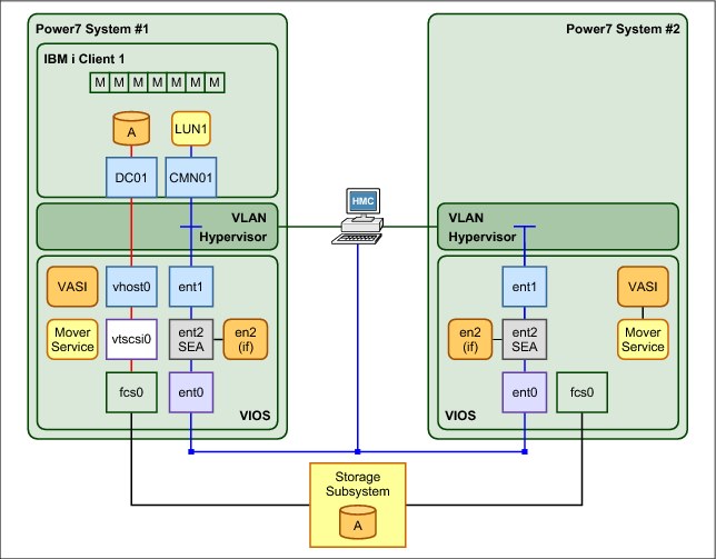
Figure 7-26 Basic hardware infrastructure for Live Partition Mobility
LPM helps you meet increasingly stringent service-level agreements (SLAs) because you can proactively move running partitions and applications from one server to another server.
The ability to move running partitions from one server to another server means that you can balance workloads and resources. If a key application’s resource requirements peak unexpectedly to a point where there is contention for server resources, you might move it to a more powerful server or move other, less critical, partitions to different servers, and use the freed resources to absorb the peak.
LPM can also be used as a mechanism for server consolidation because it provides an easy path to move applications from individual, stand-alone servers to consolidation servers. If you have partitions with workloads that have widely fluctuating resource requirements over time (for example, with a peak workload at the end of the month or the end of the quarter), you can use LPM to consolidate partitions to a single server during the off-peak period so that you can turn off unused servers. Then, move the partitions to their own, adequately configured servers just before the peak. This approach also offers energy savings by reducing the power to run systems and the power to keep them cool during off-peak periods.
LPM can be automated and incorporated into system management tools and scripts. Support for multiple concurrent migrations allows you to liberate system resources quickly. For single-partition, point-in-time migrations, the Hardware Management Console (HMC) interface offers easy-to-use migration wizards.
LPM contributes to the goal of continuous availability:
•Reduces planned downtime by dynamically moving applications from one server to another server
•Responds to changing workloads and business requirements when you move workloads from heavily loaded servers to servers that have spare capacity
•Reduces energy consumption by allowing you to easily consolidate workloads and turn off unused servers
LPM is the next step in the IBM PowerVM continuum. It can be combined with other virtualization technologies to provide a fully virtualized computing platform that offers the degree of system and infrastructure flexibility that is required by today’s production data centers.
7.9.1 Requirements for Live Partition Mobility
The following items are requirements for LPM:
•The HMC must be used to manage both source and destination systems.
•HMC Version 7 Release 5 or later is required.
•Both source and destination systems must be an IBM Power Systems POWER7 technology-based model with firmware service pack 730_51, 740_40, or later.
•Both source and destination systems must have the PowerVM Enterprise Edition license code installed.
•All I/O resources of the mobile partition must be virtualized using VIOS, whether they are VSCSI, NPIV, or Virtual Ethernet.
•VIOS 2.2.1.4 or later is required.
•Both source and destination systems must use same external storage.
•An IBM i mobile partition must be running IBM i 7.1 with the latest Technology Refresh.
7.9.2 Considerations for Live Partition Mobility
The following items are considerations for LPM:
•The mobile partition must have all disks backed by physical volumes.
•The mobile partition must not be assigned a virtual SCSI optical or tape device or have an NPIV attached tape device that is varied on.
•The mobile partition cannot be activated with a partition profile that has a virtual SCSI server adapter, and it cannot be host another partition.
•The mobile partition cannot be activated with a partition profile that has a virtual SCSI client adapter that is hosted by another IBM i logical partition.
•No virtual SCSI server adapters can be dynamically added to the mobile partition.
•No virtual SCSI client adapters that are hosted by another IBM i logical partition can be dynamically added to the mobile partition.
•The mobile partition must not be an alternative error logging partition.
•An alternative error logging partition is a target from the HMC for error logs.
•The mobile partition cannot collect physical I/O statistics.
•The mobile partition must not be a time reference partition. The VIOS synchronizes the time between partitions automatically as part of the migration.
7.9.3 Preparing Live Partition Mobility
To prepare for LPM, complete the following steps:
1. Ensure that both source and destination systems have capabilities for LPM, as shown in Figure 7-27.

Figure 7-27 Power system Capabilities of LPM
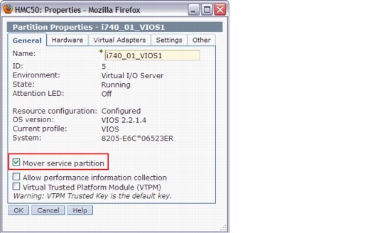
Figure 7-28 Set VIOS as Mover Service Partition
3. Ensure that Resource Monitoring and Control (RMC) connections are established between both the source and destination VIOS logical partitions and HMC.
Sign on HMC with the correct authority and run lspartition -dlpar, as shown in Example 7-4, to check the RMC connection between the HMC and VIOS.
Example 7-4 Check the RMC connection between the HMC and VIOS
#commands:
lspartition -dlpar
#Results:
<#23> Partition:<5*8205-E6C*06523ER, , 172.16.26.99>
Active:<1>, OS:<AIX, 6.1, 6100-07-04-1216>, DCaps:<0x4f9f>, CmdCaps:<0x1b, 0x1b>, PinnedMem:<799>
Active:<1> in the results means that the RMC connection is activated.
4. Verify that the same SAN disks that are used as virtual disks by the IBM i mobile partition are assigned to the source and destination VIOS logical partitions,. Also, ensure that the reserve_policy attributes of the shared physical volumes are set to no_reserve. Sign on both source and destination VIOS logical partitions with the correct authorities and run the commands that are shown in Example 7-5.
Example 7-5 Verify that the physical volumes on external storage are set correctly
List attributes of a physical volume, use the following command:
#lsdev -dev hdiskX -attr
If reserve_policy is not set to no_reserve, use the following command:
#chdev -dev hdiskX -attr reserve_policy=no_reserve
5. Ensure that the IBM i mobile partition has no physical I/O resources, and check the RestrictedIO Partition check box, as shown in Figure 7-29.
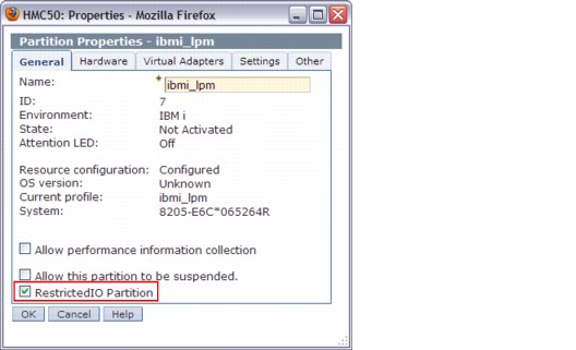
Figure 7-29 Set the IBM i mobile partition as RestrictedIO Partition
7.9.4 Validating Live Partition Mobility
Before you run a migration, complete the validation steps. These steps are optional, but can help eliminate errors. This section shows how to complete the validation steps by using the HMC GUI.
1. In the navigation pane, expand Systems Management → Servers, and select the source system.
2. In the upper right of the Hardware Management Console (Workplace), select the partition that you will migrate to the destination system.
3. Click View and select Operations → Mobility → Validate, as shown in Figure 7-30, to start the validation process.

Figure 7-30 Validate option on HMC
4. Select the destination system, specify Destination profile name and Wait time (in min), and then click Validate, as shown in Figure 7-31.
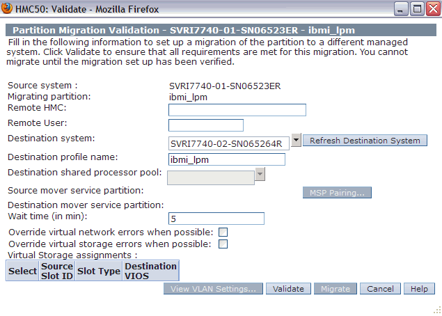
Figure 7-31 Input information for validation
5. Check for errors or warnings in the Partition Validation Errors/Warnings window, and eliminate any errors.
6. The validation window opens and with information about the destination VIOS logical partition, Virtual Storage, and VLAN, as shown in Figure 7-32. It is ready for migration.
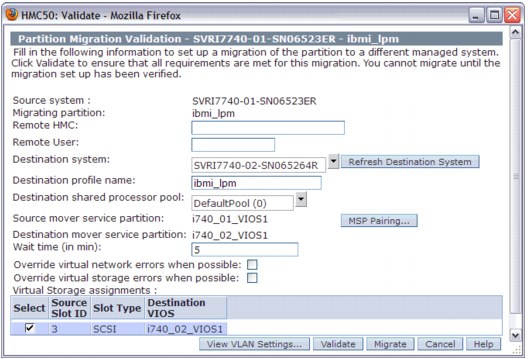
Figure 7-32 Validation window with readiness for Live Partition Mobility
7.9.5 Running Live Partition Mobility
After the validation completed, you can run LPM. This scenario shows how to migrate a IBM i logical partition named IBMi_lpm from the source system (SVRI7740-01-SN06523ER) to the destination system (SVRI7740-01-SN065264R) by using HMC. Complete the following steps:
1. In the navigation pane, expand Systems Management → Servers, and select the source system.
2. Click View and select Operations → Mobility → Migrate to start the Partition Migration wizard, as shown in Figure 7-33.
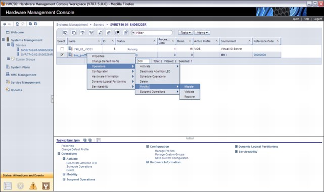
Figure 7-33 Migration menu on HMC
3. Check the migration information in the Partition Migration wizard, as shown in Figure 7-34.
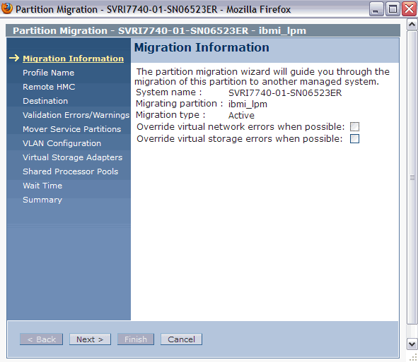
Figure 7-34 Migration Information
4. Specify the New destination profile name in the Profile Name window, as shown in Figure 7-35. If you leave the name blank or do not specify a unique profile name, the profile on the destination system is overwritten.
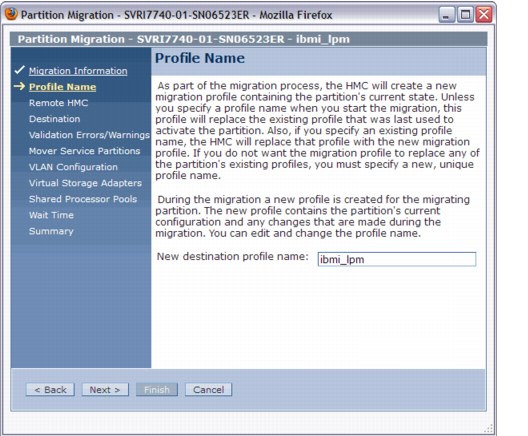
Figure 7-35 Specify destination profile name
5. Enter the Remote HMC network address and Remote User. In our example, we use a single HMC. Click Next (Figure 7-36).
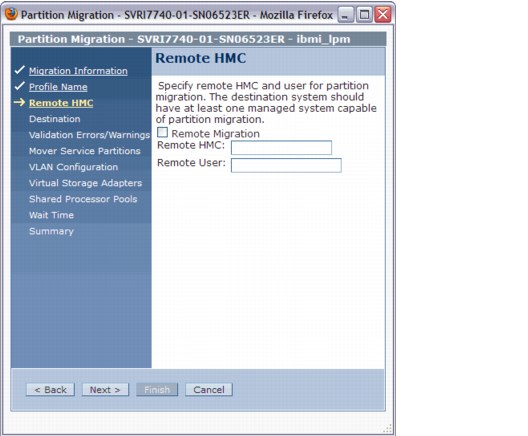
Figure 7-36 Specify the remote HMC IP address and user
6. Specify the destination system for migration, as shown in Figure 7-37. The HMC validates the partition migration environment.
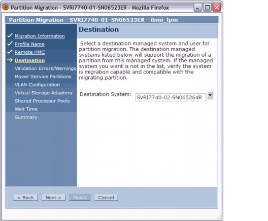
Figure 7-37 Specify destination system for migration
7. Check errors or warnings in the Partition Validation Errors/Warnings window and eliminate any errors. This step was skipped in the example because there were no errors or warnings.
8. Specify the mover service partitions to be used for migration in both source and destination systems, as shown in Figure 7-38. In this example, one Virtual I/O Server partition is configured on the destination system, so the wizard window shows only one mover service partition candidate. If you have more than one Virtual I/O Server partition on the source or on the destination system, you can select which mover server partitions to use.
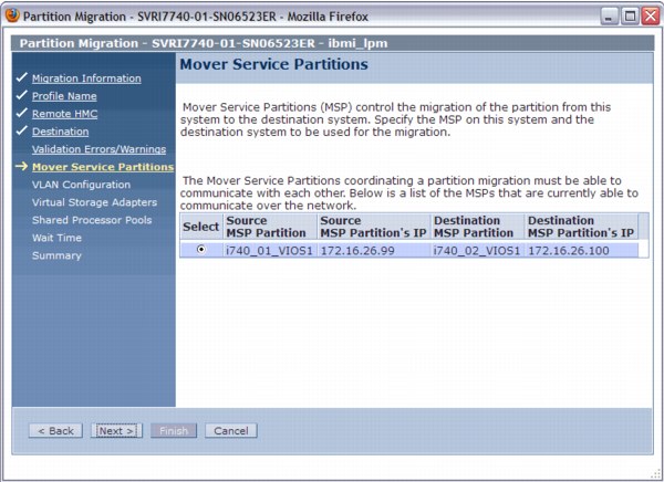
Figure 7-38 Specify MSP partitions
9. Confirm the VLAN configuration, as shown in Figure 7-39.

Figure 7-39 Confirm the VLAN configuration
10. Select the virtual storage adapter assignment, as shown in Figure 7-40. In this example, one Virtual I/O Server partition is configured on each system, so this wizard window shows one candidate only. If you have more than one Virtual I/O Server partition on the destination system, you can choose which Virtual I/O Server to use as the destination.

Figure 7-40 Select virtual storage adapters
11. Select the shared processor pools to be used by the mobile partition in the destination system, as shown in Figure 7-41.
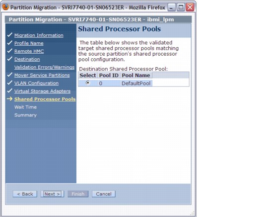
Figure 7-41 Select Shared Processor
12. Specify the wait time in minutes, as shown in Figure 7-42. The wait time value is passed to the commands that are started on the HMC and run migration-related operations on the relevant partitions using the Remote Monitoring and Control (RMC).
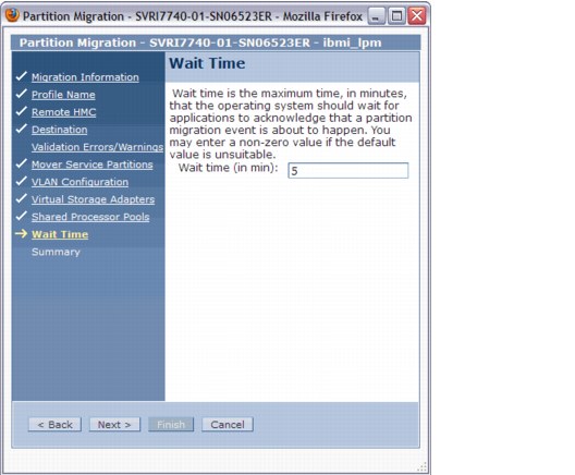
Figure 7-42 Specify Waiting time
13. Check the settings that you specified for this migration in the Summary window, and then click Finish to begin the migration, as shown Figure 7-43.

Figure 7-43 Partition Migration Summary
14. The Migration status and Progress are shown in the Partition Migration Status window, as shown in Figure 7-44.
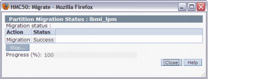
Figure 7-44 Partition Migration Status
15. When the Partition Migration Status window indicates that the migration is 100% complete, you will find that the mobile partition is running in the destination system.
7.9.6 Considerations about Live Partition Mobility
This section describes some considerations about IBM i LPM:
•Performance considerations
Active partition migration involves moving the state of a partition from one system to another system while the partition is still running. The partition memory state is tracked while it transfers the memory state to the destination system. Multiple memory transfers are done until enough clean pages are moved.
Providing a high-performance network between the source and destination mover partitions and reducing the partition’s memory update activity before migration improves the latency of the state transfer phase of migration. As a preferred practice, use a dedicated network for state transfer, with a nominal bandwidth of at least 1 Gbps.
•Licensing considerations
For a permanent partition migration, the requirements are the same as for a manual migration to a new system. For a temporary partaking migration:
– If software entitlements were acquired on all systems, move partitions where and when they are needed.
– If the software entitlements of the IBM i operating system or standard set of IBM i licensed program products are not acquired on the destination systems, you can temporarily move the partition for up to 70 days to a destination system.
You must purchase software entitlements on the source system. The source system must be equal or larger in the processor group than any destination system. After 70 days, you must acquire the entitlements on the destination system, move the entitlements back to the source system, or move the entitlements to another destination system.
•Application considerations
In general, applications and the operating system are unaware that the partition is moved from one system to another. There are some exceptions for applications that recognize system serial number, logical partition ID, and system type/model. When the partition is running on the target system, the Collection Services collector job cycles the collection so that correct hardware information is recorded on the target system.
•Exit program considerations
Two Work Management exits were added: QIBM_QWC_RESUME and QIBM_QWC_SUSPEND. There is no restriction on the number of programs register against these exit points.
– QIBM_QWC_RESUME
The Resume System exit program is called when the system becomes available again after the partition was migrated to another system or the partition resumes after hibernation.
– QIBM_QWC_SUSPEND
The Suspend System exit program is called before the system becomes temporarily unavailable because the partition is migrating to another system or the partition is hibernating.
..................Content has been hidden....................
You can't read the all page of ebook, please click here login for view all page.