

Storage and solid-state drives
This chapter describes the enhancements in recent IBM i releases i 6.1.1 and i 7.1 in the following areas:
This section describes enhancements in the areas of disk management, ASP encryption, performance instrumentation, and tape applicable to IBM i internal direct-attached and possibly external storage.
This section describes the sector format that supports the unique requirements for IBM i Single Level Storage architecture.
This section summarizes the enhancements that are related to IBM i storage area network-attached storage systems, such as native and direct attachment of IBM SAN Volume Controller and IBM Storwize storage, redundant Virtual I/O Server (VIOS) multipathing support, IBM DS5000™ native attachment, changes with IOP-less IOA attached tape libraries, and new DS8000/DS6000 performance metrics.
This section describes IBM i solid-state drive (SSD) management improvements that are related to DB2 media preference, ASP balancer, and user-defined file systems.
8.1 General and direct-attached storage management enhancements
In this section, the following general storage management enhancements that are applicable to IBM i internal direct-attached storage (DAS) and possibly external storage area network (SAN) storage are described:
8.1.1 Concurrent removal of disk units
Concurrent removal of disk units with IBM i 7.1 is now supported for SYSBAS (for example, system ASP and user ASP disk units), eliminating the need for downtime to run an IPL to the DST for removing disk units from the configuration.
Figure 8-1 shows the new Work with Removing Units From Configuration panel in System Service Tools. This panel can be accessed by clicking System Service Tools → Work with disk units → Work with disk configuration.
|
Work with Removing Units From Configuration
Select one of the following:
1. Display disk configuration
2. Display status of remove operation
3. Remove units from configuration
4. Pause the remove operation
5. Resume the remove operation
6. Cancel the remove operation
7. Cancel the remove operation and balance data in the ASP
Selection
F3=Exit F12=Cancel
|
Figure 8-1 IBM i SST Work with Removing Units from Configuration panel
Figure 8-2 shows the Remove units from configuration panel with the example of disk unit 11 from ASP1 selected to be removed. This unit can become unconfigured after the removal action.
|
Remove Units from Configuration
Type options, press Enter.
4=Remove unit from configuration
Serial Resource
OPT Unit ASP Number Type Model Name Status
2 1 21-DC78C 4328 072 DD006 RAID 5/Active
3 1 21-DD464 4328 072 DD004 RAID 5/Active
4 1 21-E72DE 4328 072 DD008 RAID 5/Active
5 1 21-E7A8D 4328 072 DD005 RAID 5/Active
6 1 21-E7CB9 4328 072 DD007 RAID 5/Active
7 1 21-DCA21 4328 072 DD003 RAID 5/Active
8 1 21-E7B11 4328 072 DD011 RAID 5/Active
9 1 21-DD3DA 4328 074 DD012 RAID 5/Active
10 1 21-E7046 4328 074 DD010 RAID 5/Active
4 11 1 21-E7557 4328 074 DD009 RAID 5/Active
12 2 21-E786C 4328 074 DD002 RAID 5/Active
F3=Exit F5=Refresh F11=Display Non-configured units
F12=Cancel
|
Figure 8-2 IBM i SST Remove Units from Configuration panel
This new disk unit removal function, as with the previously available add disk unit function, works for both SYSBAS and independent ASPs, even if the IASP is varied on.
The remove function does not allow removal if the remaining capacity can result in an exceeded ASP threshold. Media preferences for SSDs are respected by the remove function (for example, DB2 or UDFS media preferences; for more information, see 8.4, “SSD storage management enhancements” on page 411) and are honored if there is remaining capacity on the corresponding media type.
Only one remove operation for one or more disk units of a single system can be started, paused, or canceled at any time. The pause operation prevents further data allocations on the disk units that are selected for removal, similar to the *ENDALC option in STRASPBAL.
|
Important: The disk unit remove function in System Service Tools, which supports concurrent disk unit removal with applications by using the ASP, does not allow removal of all the disk units from the ASP. An IPL to DST is required to delete the ASP.
|
8.1.2 Hot spare for mirroring
The usage of hot spare disk units for mirroring is supported by IBM i 6.1.1 and later. The benefit of using hot spares is that a non-degraded array or active mirrored pair state is reached more quickly again after a disk unit failure. No manual intervention is required for resuming drive protection. Although the hot spare selection algorithm selects the hot spare resulting in the highest mirroring protection level, there are situations for which the hot spare configuration does not permit the original protection level. In this case, you might still want to manually replace the newly used hot spare with a replacement drive to reestablish the original protection level, for example, bus level mirroring protection.
For a RAID configuration, the hot spare disk unit is used as a replacement for similar or lower capacity drives. For mirroring, the capacity requirement is more stringent. The hot spare must be the same size or bigger (within 25 GB).
When a disk unit is configured as a hot spare, as shown in Figure 8-3, it is no longer visible as a non-configured or configured disk unit in the System Service Tools → Work with disk units panels. However, it still shows up in the Hardware Service Manager under the disk IOA as a unique model 51 representing a hot spare disk unit.
|
Start Hot Spare
Selecting a disk unit will start using the selected disk unit
as a hot spare.
Type option, press Enter.
1=Start Hot Spare
IOA Serial IOA Resource Serial Resource
Opt Number Name Number Type Model Name
1 1C-3300176 DC06 68-0E7A6 6717 050 DD026
1C-3300176 DC06 68-0C3CF93 6718 050 DD025
1C-3300176 DC06 68-0C357DB 6718 050 DD022
1C-3300176 DC06 68-0C36C54 6718 050 DD027
|
Figure 8-3 IBM i Start Hot Spare panel
The disk IOA does not control mirror protection, so when a mirror protected disk unit fails, the System Licensed Internal Code (SLIC) detects that the failed drive and completes the following recovery steps (not apparent to the user):
1. SLIC tells IOA to disable the hot spare.
2. The hot spare becomes non-configured.
3. The replace configured unit function is run to replace the failed drive with the now non-configured previous hot spare.
4. The failed drive becomes non-configured for safe physical replacement.
8.1.3 Dual storage I/O adapters
With IBM i 6.1.1 or later, any of the following IBM i serial-attached SCSI (SAS) adapters with write cache that is used for internal disk attachment on POWER6 server or later are supported as dual SAS adapters. Both adapters of the dual SAS adapter pair must have the same size of write cache.
•PCIe2 1.8 GB Cache RAID SAS Adapter Tri-Port 6 Gb CR sales feature #ESA3
The PCIe2 1.8 GB Cache RAID SAS Adapter Tri-Port 6 Gb CR (#ESA3) is a low-cost version of the large-cache PCIe SAS adapter (#5913). It provides high-performance capabilities for large quantities of solid-state drives (SSD) or hard disk drives (HDD). This newer version has lower energy requirements and lower cost than the #5913, yet provides about the same performance. POWER7+ servers are supported initially, with POWER7 support intended to follow.
•#5913/ESA1/ESA2 SAS Adapter Performance Boost with VIOS
Performance is boosted in a configuration of IBM i client with VIOS for the #5913/ESA1/ESA2 adapters. With this support, there is better handling of “write” workloads.
For any existing configurations with these adapters, the HDD/SSD disk drives need to be reformatted to get the boost. Another benefit is that the usable capacity on the SAS disk drives is also increased.
|
Note: VIOS 2.2.3.0 is required. For boot device support, FW780 is also required.
|
For more information about Adapter Performance Boost with VIOS, see the IBM Hardware Announcement letter 113-171 on the following website:
•PCIe2 1.8 GB Cache RAID SAS Adapter Tri-Port 6 Gb sales feature #5913
The PCIe2 1.8 GB Cache RAID SAS Adapter Tri-Port 6 Gb (#5913) is a large-cache PCIe SAS adapter that provides high-performance capabilities for large quantities of solid-state drives (SSD) or hard disk drives (HDD). Although this adapter is supported on IBM i in a VIOS configuration, caution is recommended with workloads that are heavy on writes.
The new dual SAS adapter support provides adapter redundancy with an active and passive I/O path per RAID set, or a mirrored side in a two pair (four adapters) dual SAS adapter configuration with IBM i mirroring. Read and write disk I/O operations are sent by the system only down the active path. The passive path is used only after controller failovers (for example, if the active path fails). Dual SAS adapters are redundantly interconnected through a SAS adapter-to-adapter (AA) cable that connects the top ports of the SAS adapters, and a SAS X cable that attaches to the disk expansion drawer, as illustrated in Figure 8-4.

Figure 8-4 IBM i dual SAS adapter configurations
Both SAS adapters of a dual storage IOA configuration can perform I/O to the attached disk array units. The SAS adapter that is optimized for a configured RAID set is the one driving the I/O to the disk array units. In Figure 8-4 on page 382, one SAS adapter is optimized for RAID set 0 and the other is optimized for RAID set 1.
|
Remember: For IBM i mirroring configurations, the disk units that are attached to a dual SAS adapter are each treated as a one-drive parity set.
|
For a dual SAS adapter pair, there are primary and secondary adapter roles. Only the primary adapter can perform disk management functions (such as creating a RAID array). If the primary adapter becomes unavailable, an automatic failover to the secondary adapter occurs, which becomes the primary adapter. There is no fallback to the original primary adapter when it comes back operational. The current role of a SAS adapter (as the primary or secondary adapter) can be seen by navigating to System Service Tools → Start a service tool → Hardware service manager → Logical hardware resources from the panel that shows the details for a dual SAS storage IOA. Select F14=Dual Storage IOA Configuration, as shown in Figure 8-5.
|
Dual Storage IOA Configuration
Type options, press Enter.
2=Change detail 5=Display detail 6=I/O debug
8=Associated packaging resource(s) 9=Resources associated with controlling IOP
Resource Type- Serial
Opt Name Model Status Number Operating Mode
DC07 572F-001 Operational YL3229019FB5 Secondary Storage IOA
DC04 575C-001 Operational YL3229019FB5 Auxiliary IOA
DC06 572F-001 Operational YL3229021017 Primary Storage IOA
DC05 575C-001 Operational YL3229021017 Auxiliary IOA
F3=Exit F5=Refresh F6=Print F12=Cancel
|
Figure 8-5 IBM i dual storage IOA configuration panel
You can view the disk unit paths for dual SAS adapter connected disk units that are reported as DMPxxx multipath disk unit resources. Navigate to System Service Tools → Work with disk units → Display disk unit configuration → Display disk unit path status (Figure 8-6).
|
Display Disk Path Status
Serial Resource Path
ASP Unit Number Type Model Name Status
1 1 Y2103LM0ACE5 433D 050 DMP147 Active
DMP148 Passive
1 8 Y2103LN0868T 433C 050 DMP197 Passive
DMP198 Active
2 2 Y680000FA16A 433C 050 DMP129 Active
DMP130 Passive
2 3 Y6800024F6C9 433B 050 DMP131 Active
DMP132 Passive
2 4 Y680000F12FD 433C 050 DMP115 Passive
DMP116 Active
2 5 Y68000267272 433B 050 DMP135 Passive
DMP136 Active
2 9 Y68000356821 433B 050 DMP170 Passive
DMP169 Active
More...
Press Enter to continue.
F3=Exit F5=Refresh F9=Display disk unit details
F11=Display encryption status F12=Cancel
|
Figure 8-6 IBM i dual SAS adapter disk unit path status
You can get the best performance without compromising the availability in a dual SAS adapter RAID configuration by balancing the RAID parity sets across both adapters so that each adapter is assigned an equal amount of RAID parity sets with active paths to the disk units. To achieve this availability, the parity optimization method must be set to Performance before you create any RAID 5 or RAID 6 parity sets for dual SAS RAID adapters. See Figure 8-7.
|
Select Parity Optimization
Select how you want the parity set optimized:
The current parity optimization is: Performance
Type choice, press Enter.
Select parity optimization
1. Availability
2. Balance
3. Capacity
4. Performance
Selection
4
F3=Exit F12=Cancel
|
Figure 8-7 IBM i parity optimization selection menu
For more information about IBM i dual SAS adapter support, see the “Dual storage IOA configurations” topic in the IBM Systems Hardware Knowledge Center at:
8.1.4 Encrypted ASP enhancements
The following new functions were implemented in IBM i 7.1 for ASP encryption supported by option 45 “Encrypted ASP Enablement”, which was originally introduced with IBM i 6.1:
•Start or stop ASP encryption for existing user ASPs or IASPs.
The changed encryption mode setting is applied for user ASPs when the system undergoes an IPL past DST and for IASPs when they are varied on. This situation does not mean that an IPL is required, but that the asynchronously run encryption or decryption tasks run only on a system that has undergone an IPL past DST.
|
Important: For geographic mirroring environments, encryption can be started or stopped only on the production IASP. Data is sent either encrypted or unencrypted to the backup node’s mirror copy IASP. This IASP ensures that the encryption attribute is set.
|
Figure 8-8 shows the new encryption options available by navigating to System Service Tools → Work with disk units → Work with disk configuration → Work with encryption.
|
Work with Encryption
Select one of the following:
1. Display encryption status
2. Create encrypted ASPs
3. Add units to encrypted ASPs
4. Start encryption on ASPs
5. Stop encryption on ASPs
6. Change data encryption key for basic ASPs
7. Change data encryption key for independent ASPs
Selection
F3=Exit F12=Cancel
|
Figure 8-8 IBM i work with encryption menu
•Change the data encryption key on existing encrypted user ASPs or IASPs.
The randomly generated 256-bit AES key for user ASP encryption (for example, the ASP master key that is used for IASP encryption) is securely stored in System Licensed Internal Code. This situation is the reason why a SAVSYS is preferred after you start encryption or change the encryption key, as shown in Figure 8-9.
|
Confirm Change Data Encryption Key for Basic ASPs
Note: This function may take a significant amount of time to
complete. During this function, the partition performance may
be degraded.
You should perform a Save System (SAVSYS) operation after
the data encryption key is changed.
Data will be processed on all encrypted basic ASPs.
Do not change the data encrypion key for basic ASPs again until
this operation has completed. Do not stop encryption on basic
ASPs until this operation has completed.
Press Enter to change the data encryption key.
F3=Exit F12=Cancel
|
Figure 8-9 IBM i change data encryption key confirmation panel
|
Requirement: For a clustering environment, an identical ASP master key, which protects the IASP data keys, must be manually created using the same parameter on each cluster node in the device domain to allow the IASP to be varied on.
|
8.1.5 Disk response time buckets enhancements
For a more granular disk I/O performance analysis, the disk response time buckets that were introduced with IBM i 6.1 (Table 8-1) were extended in IBM i 7.1 from six buckets to 11 buckets (Table 8-2). Although the performance data for the existing six buckets is still stored in the QAPMDISK file, the new buckets are stored separately in the new QAPMDISKRB database file.
Table 8-1 IBM i 6.1 disk response time buckets
|
IBM i 6.1 disk response time bucket
|
Range
|
|
1
|
0 < 1 ms
|
|
2
|
1 ms < 16 ms
|
|
3
|
16 ms < 64 ms
|
|
4
|
64 ms < 256 ms
|
|
5
|
256 ms < 1024 ms
|
|
6
|
>= 1024 ms
|
Table 8-2 shows the buckets extended to 11.
Table 8-2 IBM i 7.1 disk response time buckets
|
IBM i 7.1 disk response time bucket
|
Range
|
|
1
|
0 < 15 us
|
|
2
|
15 us < 250 us
|
|
3
|
250 us < 1000 us
|
|
4
|
1000 us < 4000 us
|
|
5
|
4000 < 8000 us
|
|
6
|
8000 us < 16000 us
|
|
7
|
16000 us < 64000 us
|
|
8
|
64000 us < 256000 us
|
|
9
|
256000 us < 500000 us
|
|
10
|
500000 us < 1024000 us
|
|
11
|
>= 1024000 us
|
The Performance Data Investigator in IBM Systems Director Navigator for i and the Collection Services Investigator in IBM iDoctor for IBM i are enhanced with new collection services disk response time graphs for the new buckets in IBM i 7.1.
Figure 8-10 shows the disk response time bucket visualization from the IBM Systems Director Navigator for i perspective. You can access this view by navigating to Collection Services → Disk → Disk Response Time → Detailed → Disk I/O Rates Overview – Detailed.

Figure 8-10 IBM Systems Director Navigator disk response time buckets graph
For more information about the new disk response time buckets in QAPMDISKRB, see the IBM i 7.1 Knowledge Center at:
8.1.6 Central processor complex node level mirroring
A system that has multiple central processor complex (CPC) nodes now mirrors disk units in a way that allows it to survive a node outage and that allows a concurrent maintenance repair of a CPC node.
When you start mirroring, the operating system considers the CPC node under which the disks are, and attempts to place the two subunits of a mirror protected pair under different CPC nodes. This action allows concurrent maintenance of a CPC node because the two subunits of each mirrored disk unit pair are under a different CPC node. This configuration allows at least one subunit of each mirrored disk unit pair to remain operational during the maintenance operation.
After you install the PTF Group that contains this function, you might want to consider ending and restarting mirroring to recalculate the mirror protected pairs. You can use an Advanced Analysis macro named LEVELOFPROTECTION, which is accessible through SST or DST, to verify the level of protection for each mirrored pair.
The LEVELOFPROTECTION macro is accessed from either the Dedicated Service Tools (DST) menu or the System Service Tools (SST) menu:
•To access the LEVELOFPROTECTION macro, select System Service Tools → Start a service tool → Display/Alter/Dump → Licensed Internal Code (LIC) data → Advanced Analysis.
•On the Select Advanced Analysis Command panel, there is a blank line at the top. Type a 1 in the Option column to select the blank line, then type LEVELOFPROTECTION, as shown in Figure 8-11. You can also scroll down the list and select the macro.
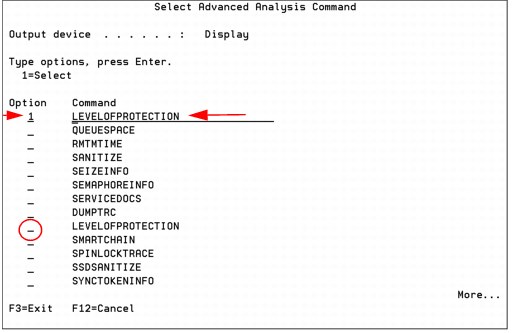
Figure 8-11 Selecting the LEVELOFPROTECTION macro
•Press Enter twice on the Select Advanced Analysis Command panel and the help panel is displayed, as shown in Figure 8-12.
Figure 8-12 LEVELOFPROTECTION macro help
•In Figure 8-13, the -UNIT parameter is chosen and disk unit 12 is entered.
Figure 8-13 Specifying the -UNIT parameter to specify a disk unit
•The macro runs and displays the panel that is shown in Figure 8-14.

Figure 8-14 Level of protection display
The line at the bottom of the display in the box indicates the level of disk protection, which in this case is CecNodeLevelOfProtection.
8.1.7 EXP24S SFF Gen2-bay drawer (#5887)
The EXP24S is a high-density, high-performance SFF drive drawer, holding up to 24 SAS drives in 2U of 19-inch rack space. It has 6 Gb of SAS I/O capability.
The #5887 drawer has double the number of drives than the EXP12S I/O drawer (#5886), and the SFF drives provide significant energy savings compared to the EXP12S 3.5-inch drives.
For more information, see IBM Hardware Announcement letter 111-065 at:
8.1.8 Higher capacity 10 K RPM SFF SAS disk drives
283 GB and 571 GB 10 K RPM SFF disk drives are available, offering a lower cost per gigabyte and more gigabytes per rack space than previous technology. These drives are available in Gen1 and Gen2 features.
For more information, see IBM Hardware Announcement letter 111-065.
8.1.9 Higher performance 387 GB SFF SSD with eMLC
Advances in technology now allow a new 387 GB SFF SSD to have more I/O operations per second (IOPS) and improved latency. IBM i support is provided for both POWER7 and POWER7+ servers, and for both IBM i 7.1 and IBM i 6.1 with 6.1.1 machine code.
For more information, see IBM Hardware Announcement letter 113-171 at the following website:
8.1.10 775 GB SFF SSD with eMLC
The new 775 GB SFF SSD, using the same technology as the new higher performance 387 GB disk drive, doubles the capacity that can fit in a single slot. IBM i support is provided for both POWER7 and POWER7+ servers, and for both IBM i 7.1 and IBM i 6.1 with 6.1.1 machine code.
For more information, see IBM Hardware Announcement letter 113-171 at the following website:
8.1.11 1.2 TB / 1.1 TB 10K RPM SAS HDD
The 1.2 TB / 1.1 TB 10k RPM SAS HDD offers lower cost per gigabyte and better storage density compared to smaller HDDs. IBM i 7.1 TR 7 supports these new drives directly. IBM i 6.1 is supported by VIOS. Both POWER7 and POWER7+ servers are supported.
For more information, see IBM Hardware Announcement letter 113-171 at the following website:
8.1.12 Tape performance instrumentation
A new Collection Services *RMVSTG category was introduced in IBM i 7.1 for performance data collection for removable media tape storage devices (for internal and external tape devices).
The tape performance statistics data are stored in the QAPMTAPE structured database file, including physical tape performance I/O statistics counts, such as number of reads and writes, bytes read and written, and number of tape marks and blocks spaced. These data are tracked by the IBM i tape code when you send requests to the tape device driver. Currently, for reviewing the data that are collected in QAPMTAPE, either a user-defined SQL query or a GUI, such as the Systems Director Navigator for i with its Investigate Data function must be used.
For more information about the structured QAPMTAPE database file performance data, see the IBM i 7.1 Knowledge Center at:
http://publib.boulder.ibm.com/infocenter/iseries/v7r1m0/index.jsp?topic=%2Frzahx%2Frzahxqapmtape.htm
8.1.13 Tape library resource name changes for IOP-less IOA attachment
When you upgrade a system to IBM i 7.1, a new hardware resource name is assigned to the tape library devices attached through an IOP-less Fibre Channel or SAS adapter. You must ensure that the tape library device description points to the correct hardware resource after the upgrade. Either the hardware resource name must be changed through the System Service Tools Hardware Resource Manager, or the device description’s resource name field must be updated (for example, by running CHGDEVMLB) with the new tape library resource name, which was assigned with IBM i 7.1.
8.1.14 Tape library unreadable barcode changes for IOP-less IOA attachment
Before IBM i 7.1, if, at varyon of the tape library, tape cartridges with unreadable barcodes are found, each of these tape cartridges is loaded into a drive to read the volume ID. The volume ID is used to generate a corresponding cartridge ID for the unreadable barcode.
This method ensures, for IBM standard labeled (VOL1) tapes, that the volume ID matches the cartridge ID, which is a requirement for IBM i to allow write operations to a tape cartridge. The downside of this approach is the time that is required to load and read each cartridge, especially if the library barcode reader itself failed. Also, problems with the barcode label or barcode reader are not made apparent to the user.
With IBM i 7.1 and IOP-less IOA attached tape libraries, if a tape cartridge with an unreadable or missing barcode is manually added, a cartridge ID with a format of UNKXXX is fabricated, with XXX being a sequential decimal number that starts with UNK001. If a cartridge is found in a storage slot with an unreadable barcode, a cartridge ID is fabricated with the format of U@XXXX, with XXXX reflecting the SCSI element address when the tape device driver discovers an unreadable barcode in a slot.
This handling of unreadable barcodes in IBM i 7.1 reveals barcode problems and allows you to read from tapes without barcode labels (which are removed from the library again) quicker, without requiring a tape drive for generating cartridge IDs.
|
Consideration: With the IBM i 7.1 IOP-less IOA tape library attachment, you should not use cartridges without barcode labels if they are supposed to remain in the library. To write or append to a standard labeled cartridge in a library, a barcode label that matches the volume ID must be stuck on the cartridge.
|
8.1.15 DVD / Tape SAS External Storage Unit for Power 795 CPC Rack
The #5274 DVD / Tape SAS External Storage Unit for Power 795 CPC Rack is a 1U storage unit that can hold HH DAT160 drives, the #5638 1.5 TB / 3.0 TB LTO-5 SAS Tape Drive, or slimline DVD drives.
For more information, see IBM Hardware Announcement letter 111-065 found at:
8.1.16 RDX support
RDX drives are positioned as an entry tape alternative to VXA-2, VXA-320, DAT72, DAT160, DAT320, or 8 mm, but they are not intended as an alternative to LTO.The offered capacities are 160 GB - 1 TB per removable cartridge.
RDX drives are available through native attach in IBM i 7.1 TR5 with either USB or SATA. SATA support will be added to 6.1.1 through a PTF. The drives are available for POWER7 systems only.
For a USB attach to a Version 7.1 system, you can either use F/C #EU03 (USB) or #EU04 (USB). For a Version 6.1.1 system, you must use F/C #EU07 (SATA).
The RDX dock is available in either 5.25-inch internal (SATA or USB) format or external USB format. The dock supports all RDX cartridges, which have 30+ years of reliability and are rugged.
8.1.17 1.5 TB RDX removable disk cartridge
A 1.5 TB RDX cartridge feature #EU15 delivers 50% more capacity than the largest cartridge previously available. It is supported in the #EU03/EU04/EU23 and #1103/1104/1123 RDX docking stations.
For more information, see IBM Hardware Announcement letter 113-006 at the following website:
8.1.18 VIOS support for RDX USB docking station for removable disk cartridge
Native and iVirtualization support has been offered since late 2012 for RDX technology. The USB RDX technology is also being supported in VIOS configurations for the same USB hardware that was supported natively. The virtual RDX device is shown in an IBM i partition as an optical device, so the same command set applies. This virtual support is useful for virtual client partition back-up, save/restore, install, and so on.
|
Note: VIOS 2.2.3.0 is required. For boot device support, FW780 or FW770.30 is also required.
|
Support is for same devices as native-attached USB RDX (#EU03 and #EU04).
For more information about RDX removable disk drives, see the following link in the IIBM Power Systems Hardware documentation:
Figure 8-15 shows a comparison matrix between low end tape drives and RDX.

Figure 8-15 RDX versus low end tape
Although RDX is a tape replacement, when you configure or operate RDX on IBM i, think of it as a DVD. The devices do not show up as TAP devices. Instead, look for a Removable Mass Storage (RMS) device.
|
Note: IBM i 7.1 can virtualize RMS devices to other IBM i partitions. VIOS does not virtualize RDX.
|
8.1.19 Use of USB flash drive for IBM i
IBM i on POWER7+ and POWER7 Systems support the use of USB attached flash drives for both native attach and iVirtualization configurations (where IBM i is serving I/O to a virtual client IBM i partition or where IBM i is a virtual client of an IBM i partition) with current PTFs.
Flash drives, also referred to as memory keys or thumb drives, are small pluggable devices that do not have removable media. The intent is to provide generic support for a USB 2.0 device (up to 32 GB in capacity) so that the USB flash vendor of choice can be used. A single flash drive can hold a large amount of data that would otherwise have needed multiple DVDs, and can typically access the data much faster.
On IBM i, these are “optical class” devices whose main purpose is data movement such as IFS copy, save/restore operations directly to/from the device, or D-mode IPL when the server is HMC managed. Due to lack of reliability of flash drives in general, they are not recommended as backup devices, but they are useful for the following types of operations:
•Copying a file (for example PTF fix, database file, or spool file) from one IBM i partition to another.
•Copying a file from an IBM i partition to another type of system, for example, a Windows 7 or Apple PC.
•Copying a mainstore dump and other debug information from an IBM i partition and taking it to another partition, or even a PC, to send it in to IBM service.
•Installing PTFs or an IBM i application.
•ISV software distribution.
•Performing a D mode IPL when managed by an HMC when an alternate IPL device is configured.
•Used as an alternative to sending files over a network.
For more information about USB attached flash drives, see the following website:
When a USB flash drive is inserted into the operator panel USB port or the Flexible Service Processor (FSP) USB ports, a storage resource type of 63BC is created. Use the WRKHDWRSC *STG command to see the created resource as shown in Figure 8-16.
|
Work with Storage Resources
System: LPARTEST
Type options, press Enter.
7=Display resource detail 9=Work with resource
Opt Resource Type-model Status Text
CMB08 57D3-001 Operational Storage Controller
DC05 57D3-001 Operational Storage Controller
RMS01 63BC-005 Operational Optical Storage Unit
|
Figure 8-16 Storage resources
When a flash drive is initialized (INZOPT) on IBM i, it is initialized with the UDF file system. If a flash drive is inserted that has files on it, but displays on the system as an unknown format, it is most likely formatted with a file system that IBM i does not recognize (for example, Microsoft NTFS).
Save/restore operations are run as with a DVD, for example SAVLIB DEV(RMS01). Because it is an optical class device, you can also use IFS to manage data by using the command WRKLNK OBJ('/QOPT/RDXVOL'). IBM i commands are the normal optical storage commands (INZOPT, WRKOPTVOL, and so on).
8.1.20 POWER7+ 770/780 Native I/O support
For POWER7+ 770 or 780 systems, native I/O attach is supported only for IBM i 7.1. IBM i 6.1 partitions can use native I/O only if virtualized by a VIOS or a Version 7.1 partition, as shown in Figure 8-17.
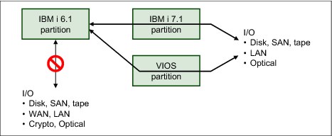
Figure 8-17 POWER7+ native I/O
Although this virtualization is easily done for disk, SAN, Tape, LAN, and optical devices, there is no virtualization support for WAN or crypto cards.
8.2 Using IBM i 520-byte sector SAS disk through VIOS
Historically, virtual SCSI disk devices presented to client operating systems from both the Virtual I/O Server (VIOS) and the IBM i (when acting as a virtual storage server) have always been formatted to use a 512-byte sector size. Because of the unique requirements to implement its Single Level Storage architecture, for every 512 bytes of data written to disk, an IBM i partition must also store 8 bytes of additional data. Some storage devices, such as the DS8000 family of storage servers when attached directly to the IBM i partition, provide a 520-byte sector format to support this requirement. However, when using 512-byte sector devices, the IBM i operating system instead must use an additional sector for every eight sectors written to disk. This requirement consumes 4608 bytes of disk space for every 4096 bytes of user data written. This additional sector is used to store the additional data that would otherwise have been written in each 520-byte sector by devices capable of that support.
The latest generation of IBM Serial-Attached SCSI (SAS) adapters are optimized for disk operations with data aligned on 4096-byte boundaries. This decision ended up producing a noticeable degradation of the performance of disk requests with data that was not aligned on such a boundary. Specifically, virtual disk units provided to an IBM i client partition from a VIOS server using SAS hdisks as the backing storage devices. In this configuration, the 4608 byte-aligned I/O requests initiated by the IBM i are passed to the SAS adapter with no change in alignment, resulting in less than optimal performance.
IBM has addressed this performance issue by enabling the VIOS to provide a 520-byte sector format virtual disk when backed by SAS hardware that is capable of supporting that format, and enabling the IBM i operating system to format and use these virtual disks like they would other 520-byte sector disks. The SAS adapter then optimizes the I/O as though it was attached directly to the IBM i partition instead of being attached to a VIOS.
8.3 SAN storage management enhancements
This section describes the following IBM i storage management enhancements specific to IBM i external storage area network (SAN) storage:
8.3.1 IBM SAN Volume Controller and IBM Storwize storage systems
IBM SAN Volume Controller and IBM Storwize V7000, IBM Storwize V3700, and IBM Storwize V3500 storage systems are supported for both fabric and direct attached configurations. Loadsource device support is included, as is the full use of PowerHA for i, including Logical Unit (LUN) level switching.
For more information about PowerHA support, see the following website:
Support is for all models of the IBM SAN Volume Controller and IBM Storwize storage systems that have IBM SAN Volume Controller code level 6.4.1.4, or later.
Following are some configuration tips:
•Each host Fibre Channel port can be configured to support 1 or 2 paths to a maximum of 64 LUNs.
•Each IBM i Fibre Channel port logs in to one port on each of the controller nodes.
•The recommended switch zoning is to have one host Fibre Channel port and one port from each node included in the same zone.
•There is support for variable sized LUNs on the IBM Storwize storage systems, but 80 GB is the recommended minimum LUN size to create.
•Having a few large LUNs is not considered a best practice because better performance is achieved when data can be spread across multiple LUNs. Use Disk Magic to characterize your workload to understand how many LUNs are required.
•When setting up the configuration, formatting the LUNs before assigning them to the IBM i host partition is recommended when reusing storage that had an IBM i LUN that was deleted.
•Because there is no support for host side SSD identification, the IBM i ASP balancer function does not recognize the IBM Storwize LUNs as SSD. Therefore, the IBM Storwize storage system should be configured for EasyTier. See the following techdoc for a summary of IBM i supported storage:
For compatibility and availability information about IBM SAN Volume Controller, see the IBM System Storage SAN Volume Controller website:
8.3.2 Multipathing for virtual I/O
IBM PowerVM Virtual I/O Server IBM i client support was introduced with IBM i 6.1.
With IBM i 6.1.1 or later, a redundant VIOS configuration (Figure 8-18) is supported by IBM i multipathing across two or more VIOS on the same IBM Power Systems server for protection against VIOS outages because of VIOS updates.

Figure 8-18 IBM i multipathing with a redundant Virtual I/O Server configuration
This new IBM i multipathing support for virtual I/O eliminates the need to use IBM i mirroring for a redundant VIOS configuration, which required duplicate storage capacity.
For further IBM i virtualization enhancements, such as Active Memory Sharing or N_port ID virtualization support, see Chapter 7, “Virtualization” on page 319.
8.3.3 DS5000 native attachment
IBM i SAN storage support is extended with IBM i 6.1.1 to support native attachment of the IBM System Storage DS5100 and DS5300 systems to IBM Power Systems POWER6 or later servers. This new native attached DS5100 and DS5300 storage support provides an easier storage setup (see Figure 8-19) and configuration without needing to deploy the IBM PowerVM VIOS. It is only if some other advanced virtualization functions are being used on IBM i that you must configure a VIOS.

Figure 8-19 IBM i DS5000 native attachment
Figure 8-20 shows how the native attached DS5000 LUNs, created for the IBM i host, report on an IBM i host as device type D818.
|
Display Non-Configured Units
Serial Resource
Number Type Model Name Capacity Status
Y2103LQ0WGLC 433B 050 DPH001 69793 Non-configured
Y2103LQ1J064 433B 050 DPH002 69793 Non-configured
Y2103LQ1J06H 433B 050 DPH003 69793 Non-configured
Y2103LQ0P0BE 433B 050 DPH004 69793 Non-configured
Y2103LQ1HV0C 433B 050 DPH005 69793 Non-configured
Y2103LQ1J6M8 433B 050 DPH006 69793 Non-configured
Y0C44AC5B4F6 D818 099 DPH007 265333 Non-configured
Y0C14AC5A32B D818 099 DPH008 265333 Non-configured
Press Enter to continue.
F3=Exit F5=Refresh F9=Display disk unit details
F11=Display device parity status F12=Cancel
|
Figure 8-20 Native attached DS5000 LUNs on IBM i
|
Storage capacity: Because of the 4 KB page sector conversion from 8 x 520 bytes sectors to 9 x 512 bytes sectors by IBM i SLIC for DS5000 native attachment, the reported usable IBM i capacity is approximately 89% of the configured DS5000 LUN capacity.
|
The built-in IBM i multipathing in System Licensed Internal Code (SLIC) adheres to the DS5000 active / passive controller concept. Under normal working conditions, I/O is driven across only the active paths to a disk unit (to the controller designated for the LUN as the preferred controller) when the passive paths for a disk unit are used at DS5000 controller failover conditions. Figure 8-21 shows the active and passive path for disk units from a native attached DS5000 after they are added to an ASP. You can access this panel by navigating to System Service Tools → Work with disk units → Display disk configuration → Display disk path status.
|
Display Disk Path Status
Serial Resource Path
ASP Unit Number Type Model Name Status
2 25 Y0C14AC5A32B D818 099 DMP002 Active
DMP004 Passive
2 26 Y0C44AC5B4F6 D818 099 DMP001 Passive
DMP003 Active
Press Enter to continue.
F3=Exit F5=Refresh F9=Display disk unit details
F11=Display encryption status F12=Cancel
|
Figure 8-21 IBM i active / passive paths for DS5000 disk units
IBM i DS5000 native attachment has these requirements:
•IBM i POWER6 or later servers only
•IBM i 6.1.1 (OS resave RS610-10, SLIC RS611-A, or cumulative PTF C9279610) or later
•IOP-less Fibre Channel IOA (#5774, #5749, or #5735)
•DS5100 or DS5300 only
•DS5000 FW 7.60.28.00 or later (including NVSRAM N1818D51R1060V08 for DS5100 and N1818D53R1060V08 for DS5300 or later)
•DS5000 Storage Manager 10.60.x5.17 or later
•DS5000 IBM i Host Kit Feature Code 7735
The following considerations apply for IBM i DS5000 native attachment:
•The maximum supported LUN size for IBM i is less than 2 TB.
•The usable IBM i net capacity is 8 / 9 of the configured DS5000 LUN capacity.
•A maximum of 64 LUNs per IBM i Fibre Channel IOA port is allowed.
•Unprotected arrays (RAID 0) are not supported for IBM i.
•IBM i mirroring is not supported for DS5000.
•Multipathing on a single dual-port Fibre Channel IOA is not supported.
•DS5000 Dynamic Volume Expansion (DVE) is not supported for IBM i.
•SSDs in DS5000 are not supported for IBM i.
From an IBM i disk I/O performance perspective, the following preferred practices should be followed:
•To balance workload across both DS5000 controllers, LUNs should be evenly assigned regarding preferred controller affinity to controller A and B.
•The LUN size for IBM i IOP-less Fibre Channel of 70 GB applies for DS5000 native attachment.
•A DS5000 segment size of 128 KB is generally a good compromise for both IBM i transaction and save / restore workload.
For more information about the IBM System Storage DS5000 series, see the following IBM Redbooks publications:
•IBM Midrange System Storage Hardware Guide, SG24-7676
•IBM System Storage DS Storage Manager Copy Services Guide, SG24-7822
For more information about IBM support statements about DS5000 Copy Services support with IBM i native attached DS5000, see IBM i Virtualization and Open Storage read-me first, found at:
IBM STG Lab Services developed a Copy Services Tool Kit offering Advanced Copy Services for PowerHA - DS5000 Edition for DS5000 native-attachment to support IASP storage-based replication solutions with FlashCopy / VolumeCopy and Enhanced Remote Mirroring. For more information about this Copy Services Tool Kit offering for DS5000, see IBM STG Lab Services at:
8.3.4 Level of protection reporting for multipath disk units
With IBM i 7.1, the level of protection for multipath attached external disk units is now reported for any multipath disk unit devices from either a natively or VIOS-attached disk storage system. The reported levels of multipath protection reflect the component that can fail without jeopardizing I/O access to the disk units and are the same as the ones used for mirrored protection:
•Remote Bus
•Ring (HSL / 12X Loop)
•Tower
•Bus
•IOP
•IOA
•IOA-Bus
Figure 8-22 shows the new multipath protection level reporting for the example of DS8000 disk units each attached through three paths. To view this panel, select System Services Tools → Work with disk units → Display disk unit configuration → Display protection for multiple connection disk units.
|
Display Protection for Multiple Connection Disk Units
Serial Resource
ASP Unit Number Type Model Name Protection
7 11 50-70005F0 2107 A04 DMP007 Ring
7 11 50-70005F0 2107 A04 DMP012 Ring
7 11 50-70005F0 2107 A04 DMP009 Ring
7 14 50-53007F0 2107 A04 DMP407 Bus
7 14 50-53007F0 2107 A04 DMP111 Bus
7 14 50-53007F0 2107 A04 DMP208 Bus
Press Enter to continue.
F3=Exit F5=Refresh
F11=Display disk configuration status F12=Cancel
|
Figure 8-22 IBM i protection level reporting for multipath disk units
8.3.5 Library control paths for IOP-less Fibre Channel IOA tape attachment
Tape library devices that are attached to a dual-port Fibre Channel I/O adapter with IBM i 7.1 require at least one control path drive to be attached to each port. This configuration is required because the design changed from an adapter-centric to a port-centric control path architecture.
The tape device driver ensures that, from a user perspective, only one library resource per Fibre Channel IOA port is presented for the same logical library, even if multiple control paths are defined. IBM i pools these libraries so all the TAPxx resources for the library are in one TAPMLBxx device description.
|
Requirement: For IBM i 7.1, a second library control path must be added, preferably before the upgrade to IBM i 7.1, for the second port of a dual-port IOP-less Fibre Channel IOA. Otherwise, the tape drives on the second port can become stand-alone devices without library capability.
|
Before IBM i 7.1, only one control path drive was required per Fibre Channel IOA for drives in the same logical library. Only one library resource per Fibre Channel IOA is presented for the same logical library, even if multiple control paths are defined.
8.3.6 External disk storage performance instrumentation
New external disk storage performance metrics for IBM System Storage DS8000 and DS6000 series are available with Collection Services in IBM i 7.1. This new data is collected with the new *EXTSTG category and stored in the QAPMXSTGD database file.
Because of a minimum DS8000 Release 4 microcode requirement to support this new external storage performance data collection, the *EXTSTG category is not included in any default collection profile to prevent Product Activity Log (PAL) hardware failure information entries if this DS8000 code requirement is not met. To enable QAPMXSTGD external storage performance data collection with the *STANDARD or *STANDARDP default collection profiles, the following steps as are required to add the *EXTSTG category to these profiles:
1. Run ENDPFRCOL FRCCOLEND(*YES).
2. Run RNMOBJ OBJ(QUSRSYS/QPFRCOLDTA) OBJTYPE(*USRSPC) NEWOBJ(QPFRCOLDT2).
3. Run CALL QSYS/QYPSCOLDTA PARM(’*EXTSTG’).
4. Run STRPFRCOL.
For more information about these DS8000 external storage performance data collection requirements, see the IBM i Memo to Users 7.1 at:
|
Requirement: DS8000 Microcode Release 4 or later is required for the QAPMXSTGD external storage performance data collection.
|
This new QAPMXSTGD database file contains DS8000 or DS6000 external storage subsystem performance data, including Fibre Channel link statistics and rank (RAID array) statistics. The QAPMXSTGV database file that was introduced in IBM i 6.1.1 and part of the *DISK category included in all default collection profiles contains volume level (that is, logical unit (LUN)) cache statistics performance data.
Both the QAPMXSTGD and QAPMXSTGV files store vendor-specific SCSI Log Sense page data in unstructured large data fields. Access to at least a single IBM i LUN on the DS8000 or DS6000 storage system is required to retrieve this log sense data from it when the SCSI Log Sense command is issued against a LUN.
IBM iDoctor for IBM i external storage performance analysis functions
The IBM iDoctor for IBM i suite of analysis tools is recommended for analyzing the external storage performance data. IBM iDoctor for IBM i build C00777 or later is required. This suite has new functions for visualizing and analyzing DS8000 or DS6000 storage performance data.
The new iDoctor Collection Services Investigator functions for analyzing the external storage performance log sense data that is stored in QAPMXSTGV (Log sense page 0x32) and QAPMXSTGD (Log sense pages 0x33 and 0x34) are shown in Figure 8-23.
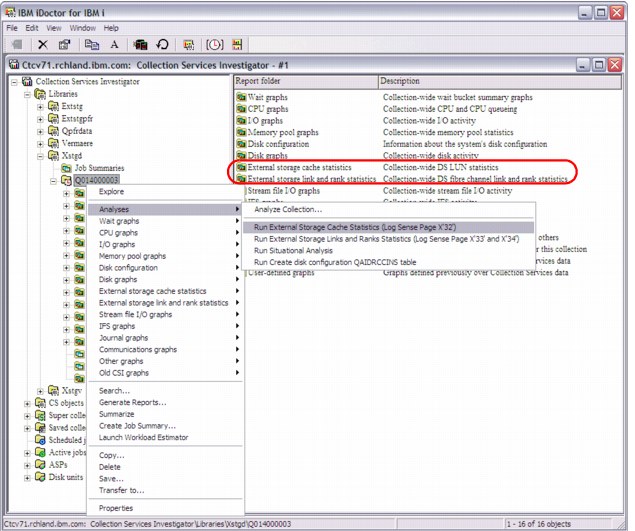
Figure 8-23 iDoctor analysis functions for external storage
Before you use iDoctor to analyze the external storage performance data, click Analyses → Run External Storage to generate structured SQL tables from the Log Sense data and the new “External storage cache statistics” and “External storage link and rank statistics” report folders. A refresh of the view might be required to display them.
Newly available external storage cache statistics data are shown in Figure 8-24 from the report that is generated by clicking External storage cache statistics → by time interval → IO rates totals with cache hits. The read cache hit% information was available from the QAPMDISK data, but the newly reported write cache hit% from QAPMXSTGV data can check for any potential storage subsystem write cache overruns. These overruns are indicated by write cache hits% < 100%, and might warrant changes in the workload schedule or a cache size upgrade.
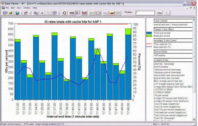
Figure 8-24 iDoctor external storage cache statistics
Valuable analysis functions for DS8000 or DS6000 rank and link performance data are available from the External storage link and rank statistics reports.
For example, potential rank overuse issues can easily be visualized and analyzed by using a ranking view of the rank IDs based on total I/O. To do so, click Rank graphs → By rank ID → Ranks IO rates totals. Then, from this view, select one or more ranks with a high I/O rate for a more detailed analysis by selecting Selected Ranks → Ranks IO rates from the right-click menu, as shown in Figure 8-25.
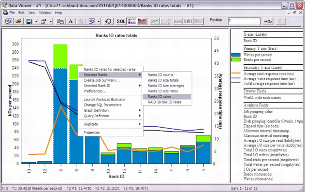
Figure 8-25 iDoctor rank I/O rates ranking
The read and write rank I/O rates over time for the individually selected rank IDs 5 and 6 from the example are shown in Figure 8-26. If these were RAID 10 instead of RAID 5 ranks, you also could have chosen the option to display the disk IO rates. This option is not available for RAID 5 because their disk I/O rates cannot be determined accurately from the rank read and write I/O rates.
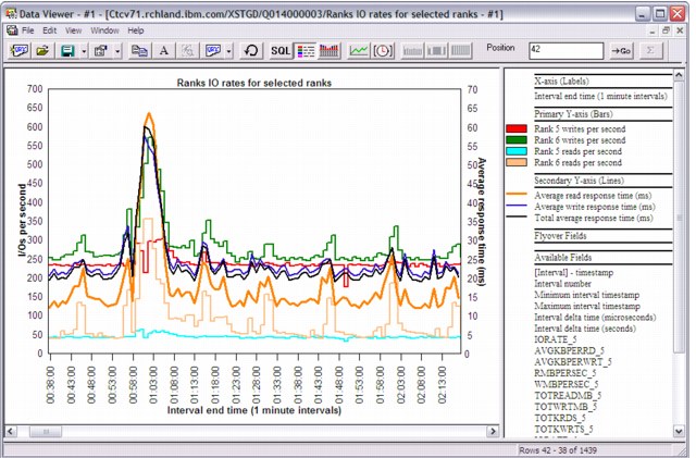
Figure 8-26 iDoctor rank I/O rates for selected ranks
Similar to the rank I/O performance analysis, reports with graphing functions for host (SCSI) or Peer-to-Peer Remote Copy (PPRC) link performance analysis were added to iDoctor, as shown in Figure 8-27.

Figure 8-27 iDoctor link I/O rates
For more information about the IBM iDoctor for IBM i powerful suite of performance tools, go to the iDoctor website, which offers a 45-day trial version, at:
8.3.7 Thin provisioning for DS8700, DS8800, and VIOS shared storage pools
Thin provisioning for DS8700 and DS8800 storage servers, and for VIOS shared storage pools, allows configurations to be set up with a small amount of real disk storage. This storage can be increased later without changing the partition's view of the storage LUN. Before this enhancement, the full amount of configured storage was allocated at LUN initialization time.
Here are the thin provisioning requirements:
•Hardware requirements:
Thin provisioning enhancement for DS8000 storage servers requires a DS8700 or DS8800 with Release 6.2, available from IBM through FC #1723, or through bundles:
– IBM System Storage DS8700 - level 7.6.2.xx.xx (bundle version 76.20.xxx.xx), or later
– IBM System Storage DS8800 - level 7.6.2.xx.xx (bundle version 86.20.xxx.xx), or later
•Software requirements: IBM i 7.1 with the newest Technology Refresh PTF Group
8.4 SSD storage management enhancements
IBM i with its single-level storage architecture, integrated DB2 database, storage performance analysis, and storage management capabilities is an industry-leading platform for SSD hierarchical storage management.
The integrated hierarchical storage management functions for SSDs in IBM i, such as the DB2 for i and UDFS media preferences or the ASP balancer enhancements for SSDs, allow for an easy and efficient implementation of SSDs on the IBM i platform.
SSDs based on flash memory are considered a revolutionary technology for disk I/O performance and energy efficiency compared to traditional spinning disk drives. SSD I/O response times can be over 200 faster than for spinning disk drives. SSDs are supported in IBM i 6.1.1 for internal storage plus PTF MF47377 or later if used in IBM System Storage DS8000 series with R4.3 code or later.
For more information about the benefits and usage of SSDs with IBM i, see Performance Value of Solid State Drives using IBM i, which is available at the following website:
The SSD Analyzer Tool for IBM i is a good tool to use for a first analysis about whether SSDs can help improve performance for a particular IBM i system. The tool queries existing Collection Services performance data for retrieving the average system and optional job level disk read I/O response times to characterize whether the workload is a good candidate for SSDs. It can be downloaded as an IBM i save file from the following website:
For a reference about the IBM i PTF requirements for SSDs, see the IBM i Software Knowledge Base topic “Requirements for Solid State Drives (SSD)”, which is available at the following website (search for KBS document number 534676318):
The following subsections describe recent enhancements for management of SSDs in an IBM i environment:
8.4.1 DB2 media preference
DB2 for i was extended with support for database object placement on SSDs or HDDs. This new function, called DB2 media preference, allows the user to have control over which media type selected database files are stored so that DB files that are known to be I/O performance critical can be placed explicitly on high performing SSDs.
Physical and logical DB files (table and indexes) are enhanced with a preferred media attribute that can be set through the -UNIT parameter for a certain media preference of either SSDs. You can use UNIT parameter values *SSD (CL commands) or SSD (SQL) for i 6.1 and later, or HDDs with UNIT parameter values *ANY (CL commands) or ANY (SQL) when you create or change these files through the following CL commands or SQL statements:
•CRTPF, CRTLF, CRTSRCPF, CHGPF, CHGLF, and CHGSRCPF
•CREATE TABLE, CREATE INDEX, and ALTER TABLE
|
Parameter usage:
•The UNIT parameter for the SQL statements is supported by IBM i 6.1 or later.
•For a partitioned SQL table, the ALTER TABLE statement can be used to set a media preference on a partition (member) level.
|
Figure 8-28 shows the new preferred storage unit parameter (UNIT keyword) for the CHGPF command.
|
Change Physical File (CHGPF)
Type choices, press Enter.
Access path recovery . . . . . . *SAME *SAME, *NO, *AFTIPL, *IPL
Force keyed access path . . . . *SAME *SAME, *NO, *YES
Member size:
Initial number of records . . *SAME 1-2147483646, *SAME
Increment number of records . *SAME 0-32767, *SAME
Maximum increments . . . . . . *SAME 0-32767, *SAME
Allocate storage . . . . . . . . *SAME *NO, *YES, *SAME
Preferred storage unit . . . . . > *SSD 1-255, *SAME, *ANY, *SSD
Records to force a write . . . . *SAME Number, *SAME, *NONE
Maximum file wait time . . . . . *SAME Number, *SAME, *IMMED, *CLS
Maximum record wait time . . . . *SAME Number, *SAME, *IMMED, *NOMAX
Share open data path . . . . . . *SAME *SAME, *NO, *YES
Max % deleted records allowed . *SAME 1-100, *NONE, *SAME
Reuse deleted records . . . . . *SAME *SAME, *YES, *NO
Sort sequence . . . . . . . . . *SAME Name, *SAME, *SRC, *JOB...
Library . . . . . . . . . . . Name, *LIBL, *CURLIB
More...
F3=Exit F4=Prompt F5=Refresh F12=Cancel F13=How to use this display
F24=More keys
|
Figure 8-28 IBM i CHGPF command
Dynamic data movement
Enhancements were implemented for dynamically changing the DB2 media preference, which starts a dynamic data move done synchronously.
For releases before IBM i 7.1, the following PTFs are required for a dynamic move of physical or logical database files after you change their media preference attribute. Otherwise, a save and restore of those changed database files is required to make the media preference change effective.
•IBM i 6.1.0 PTFs MF47888, MF47892, and MF47879
•IBM i 6.1.1 PTFs MF47889, MF47893, and MF47877
DB2 random and sequential reads statistics
To help with SSD media management from a database business logic perspective for determining which database files are good candidates for placement on SSDs, two new fields (RANDOM_READS and SEQUENTIAL_READS) were introduced in IBM i 7.1 for each keyed logical and physical database file. These two 8-byte counters are used to track the amount of random and sequential logical read I/O for each database file, and are continuously updated by the database and reset only at IPL. Because a single logical read I/O can lead to more than one random I/O (for example, because of variable length fields (> 32 KB) or large objects (LOBs)), the new RANDOM_READS and SEQUENTIAL_READS usually do not sum up to the reported LOGICAL_READS.
The preferred procedure (after database performance optimization is completed from an application and system perspective and further optimization is warranted at the storage hardware level) is to help determine which database files are good candidates for placement on SSDs as follows:
1. Look at a storage I/O performance critical time period.
2. Compare the RANDOM_READS numbers at the start and end of the time period.
3. Determine the DB files with highest RANDOM_READS I/O count differences, and if these files are critical from a business perspective, they might be good candidates for using DB2 media preference to move them to SSDs.
To query the RANDOM_READS counter for database files, a SQL query against QSYS2/SYSPARTITIONSTAT for physical file statistics or SYSINDEXSTAT for keyed logical file statistics (Example 8-1) or the System i Navigator’s Health Center activity tab (Figure 8-29) can be used. Save the query results and use the View History function to compare the results that are retrieved for the start and the end of the critical time period.
Example 8-1 SQL query for physical database file random reads
SELECT table_name, logical_reads, random_reads, sequential_reads FROM QSYS2.SYSPARTITIONSTAT WHERE logical_reads > 0 ORDER BY random_reads DESC
Figure 8-29 shows the System i Navigator’s Health Center activity tab.

Figure 8-29 System i Navigator database health center+
Macro for changing storage management SSD allocations
To prevent newly created objects without a media preference from being placed on SSDs in a hybrid ASP with HDDs and less capacity used SSDs, run the smgetstayoffssd macro. After you run the macro, storage management tries to stay away from SSDs for non-media preference objects, as shown in Example 8-2. The smresetstayoffssd macro resets the storage allocation setting back to the default setting of “Non-media preference will go to best unit”, that is, the lowest percent capacity unit.
Example 8-2 Macro smgetstayoffssd
DISPLAY/ALTER/DUMP
Running macro: SMGETSTAYOFFSSD
Non-media preference will try to stay off SSD.
In Example 8-3, the smgetstayoffssd macro is used to reset the storage allocation setting back to the default for a specific independent ASP. For IASPs, the ASP number in hex is required on the smsetstayoffssd macro.
Example 8-3 Storage allocation setting
DISPLAY/ALTER/DUMP
Running macro: SMGETSTAYOFFSSD 91
Non-media preference will try to stay off SSD for ASP 0x91.
Statistical view for reporting unit allocations
A new view named SYSPARTITIONDISK, which is used to support reporting of SSD versus HDD space usage for SQL tables and native tables (physical files), is available through PTFs for IBM i 6.1, and 7.1.
Figure 8-30 shows a query result example from the new SYSPARTITIONDISK view after you use the ASP balancer to move DB files to SSD and manually move the HSTRY01 table to SSD through DB2 media preference. For each table, the columns SSD_SPACE versus NON_SSD_SPACE show its storage space in bytes allocated on SSDs and non-SSDs (HDDs).
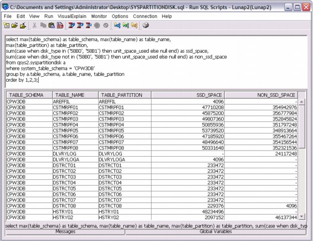
Figure 8-30 SYSPARTITIONDISK view query result
For more information about the new SYSPARTITIONDISK view and function, see the topic “IBM DB2 for i Statistical View for Solid State Drive Storage Usage Reporting” at:
8.4.2 ASP balancer enhancements for SSDs
The ASP balancer function for hierarchical storage management (HSM), which traditionally supports data migration between high performance and low performance (that is, compressed) hard disk drives (HDDs), is extended to support data migration between SSDs and HDDs.
Based on the read I/O count statistics for each 1 MB auxiliary storage extent of an ASP collected during a preceding TRCASPBAL run, the ASP balancer enhanced HSM function supports migration of frequently accessed hot extents from HDDs to SSDs and rarely accessed cold extents from SSDs to HDDs. By default, the ASP balancer tries to place all those frequently accessed extents on SSDs, which account for 50% of the total read I/O count.
Typically, the ASP balancer tracing function TRCASPBAL is run over a critical I/O workload period, such as a batch processing window, which is optimized for performance when using SSDs. Afterward, the ASP balancer HSM function is started to migrate both the cold data from SSDs and the hot data to SSDs. TRCASPBAL can be accumulative. Users might clear data at the start of the week, collect the trace across the nightly batch work load window for the week, and balance on the weekend.
Example 8-4 illustrates a typical usage of the ASP balancer tracing and migration functions by clearing the trace statistics first, collecting new trace statistics, starting the migration, and monitoring its completion with the CHKASPBAL command.
Example 8-4 ASP balancer tracing and migration
TRCASPBAL SET(*CLEAR) ASP(1)
TRCASPBAL SET(*ON) ASP(1) TIMLMT(*NOMAX)
...
TRCASPBAL SET(*OFF) ASP(1)
STRASPBAL TYPE(*HSM) ASP(1) TIMLMT(*NOMAX)
CHKASPBAL
The initial ASP balancer accounting only for the extent read I/O counts is enhanced with a more efficient migration algorithm in the weighted ASP balancer version and more functions regarding SSD media management.
Weighted ASP balancer
Enhancements were implemented for the HSM function of the ASP balancer for migration of frequently accessed hot data to SSDs and infrequently accessed cold data to HDDs for hybrid ASPs consisting of SSD and HDD disk units.
With IBM i 6.1 plus supersede PTF MF49399, IBM i 6.1.1 plus supersede PTF MF48544, and with IBM i 7.1 base code, the ASP balancer’s decision for moving hot or cold data to and from SSDs is now based on a weighted disk read I/O count for the 1 MB auxiliary storage segments to be moved. Not only is the amount of read I/O accesses to a segment counted as before, but its read service time is considered for the migration decision.
This weighted ASP balancer enhancement accounting for the read service times provides more efficient data media placement. For example, frequently accessed data that is derived mainly from read cache hits can no longer be prioritized for migration to SSDs, as it cannot benefit from being placed on SSDs.
ASP balancer migration priority
In IBM i 7.1, the ASP balancer is enhanced with an option that allows the user to specify the migration priority for *MOVDTA, *HSM, or *MP operations at levels of either *LOW, *MEDIUM, or *HIGH (as shown in Figure 8-31). This option influences the number of SLIC internal data moving tasks that are used for the migration. This option is subject to an inherent trade-off between speed of data migration and its effect on disk usage.
|
Start ASP Balance (STRASPBAL)
Type choices, press Enter.
Balance type . . . . . . . . . . *CAPACITY, *USAGE, *HSM...
ASP number . . . . . . . . . . . 1-32, *ALL
+ for more values
ASP device . . . . . . . . . . . Name, *ALLAVL
+ for more values
Storage unit . . . . . . . . . . Number
+ for more values
Time limit . . . . . . . . . . . 1-9999 minutes, *NOMAX
Balance priority . . . . . . . . *MEDIUM *LOW, *MEDIUM, *HIGH
Subtype . . . . . . . . . . . . *CALC *CALC, *HDD, *SSD
Bottom
F3=Exit F4=Prompt F5=Refresh F12=Cancel F13=How to use this display
F24=More keys
|
Figure 8-31 IBM i ASP balancer migration priority
Also, the STRASPBAL command syntax has changed in IBM i 7.1 to include a new subtype parameter that, for the *HSM balance type, now allows data migration between up to three storage tiers. Tiered storage is the assignment of different categories of data to different types of storage media to reduce total storage cost. You can have the following types of data migration:
•With subtype *SSD, you can have data migration between SSDs and high performance HDDs.
•With subtype *HDD, you can have data migration between high performance HDDs and low performance (compressed) HDDs.
Unless an ASP has disk units from all three storage tiers, the default subtype *CALC can be used.
Data migration with the *HSM balance type is run in two phases, with cold data moved off from SSDs first, and then hot data moved to SSDs.
ASP balancer media preference balance type
The *MP balance type is a new ASP balancer function in IBM i 7.1 that helps correct any issues with media preference flagged DB objects or UDFS files not on their preferred media type, which is either SSDs or HDDs. This sweeper function moves objects that are marked with a media preference attribute to SSDs and non-media preference objects to HDDs when you use the default subtype *CALC. To limit the scope of media preference migration to only one direction, either the *SSD or *HDD subtype can be used for specifying the source media type for the migration.
For earlier releases, this media preference sweeper function is available with the following SST Advanced Analysis interface macros in IBM i 6.1.1 through PTF MF49299 and in IBM i 6.1.0 through PTF MF49371:
•movemediapreference asp_num priority [L M H] (The default is low.)
This macro moves data that is marked with a media preference attribute to the SSDs and non-media preference data off the SSDs.
•movemediapreferencetossd asp_num priority [L M H] (The default is low.)
This macro moves data that is marked with a media preference attribute to the SSDs.
•movemediapreferenceoffssd asp_num priority [L M H] (The default is low.)
This macro moves data that does not have the media preference attribute off the SSDs.
•movemediapreferencestatus asp_num
This macro sets the status of the sweeping.
•movemediapreferencestop asp_num
This macro ends the sweeping.
The ASP number in the asp_num variable must be specified in hex format.
A scenario for using the media preference sweeper function is after disk units are added to an ASP, then choosing the add and balance option, which does not respect the media preference. It can also be used when disk units are removed from the configuration because of media type capacity constraints within an ASP. The sweeper function can be used to correct these media preference issues after the capacity constraints are solved.
Script for ASP balancer scheduling
The CL script in Example 8-5 is provided to help set up a TRCASPBAL and STRASPBAL configuration that runs repeatedly to allow for continuous autonomous IBM i hot and cold data migration for SSD and HDD hybrid ASPs.
Example 8-5 CL script for ASP balancer scheduling
/* This program runs continuously until the job in which it runs is ended. */
/* Inputs to this program are type of balance that is to be run, the number */
/* of minutes the trace is to run, and the number of minutes the balance is */
/* to run. Once a trace and balance cycle is complete, another trace and */
/* balance cycles is started. */
/* */
/* Parameter declares. The parameters are: */
/* The balance type to run. */
/* The number of minutes the trace is to run. */
/* The number of minutes the balance is to run. */
PGM PARM(&BALTYPE &TRACEMIN &BALMIN)
DCL VAR(&BALTYPE) TYPE(*CHAR) LEN(10)
DCL VAR(&TRACEMIN) TYPE(*CHAR) LEN(4)
DCL VAR(&BALMIN) TYPE(*CHAR) LEN(4)
/* Declare for a seconds variable for use by the delay DLYJOB command. */
DCL VAR(&SECONDS) TYPE(*DEC) LEN(6 0)
/* Start tracing for ASP 1, wait for the trace to complete and end it. */
/* An extra 300 seconds is added to the wait to allow for asynchronous */
/* activity to complete. */
LABEL1: TRCASPBAL SET(*CLEAR) ASP(1)
TRCASPBAL SET(*ON) ASP(1) TIMLMT(*NOMAX)
CHGVAR VAR(&SECONDS) VALUE(&TRACEMIN)
CHGVAR VAR(&SECONDS) VALUE(&SECONDS * 60)
CHGVAR VAR(&SECONDS) VALUE(&SECONDS + 300)
DLYJOB DLY(&SECONDS)
TRCASPBAL SET(*OFF) ASP(1)
/* Start balancing, wait for the balance to complete and end it. */
/* An extra 300 seconds is added to the wait to allow for asynchronous */
/* to complete. */
STRASPBAL TYPE(&BALTYPE) ASP(1) TIMLMT(*NOMAX)
CHGVAR VAR(&SECONDS) VALUE(&BALMIN)
CHGVAR VAR(&SECONDS) VALUE(&SECONDS * 60)
CHGVAR VAR(&SECONDS) VALUE(&SECONDS + 300)
DLYJOB DLY(&SECONDS)
ENDASPBAL ASP(1)
MONMSG MSGID(CPF9899) EXEC(GOTO LABEL1)
DLYJOB DLY(300)
/* Run another trace and balance cycle. */
GOTO CMDLBL(LABEL1)
ENDPGM
For the ASP balancer SSD enhancements, run TRCASPBAL for the period of the critical workload, such as a batch window that is to be optimized by using SSDs. The provided CL script might be an alternative if no specific time frame can be identified for optimization.
8.4.3 User-defined file system media preference
You can specify that storage for objects that are created in user-defined file systems (UDFS) should be allocated from SSDs, if available. This support is provided with PTF SI39439 and all of its requisite PTFs. This support includes changes to various commands and APIs.
A new preferred storage unit (UNIT) keyword was added to the Create User-Defined FS (CRTUDFS) command, as shown in Figure 8-32. The default value is UNIT(*ANY), which indicates that there is no preferred storage media and that storage for objects in the UDFS are allocated from any available storage media. Specifying UNIT(*SSD) indicates that storage for objects in the UDFS are allocated from SSD storage media, if available. Online help text for the new keyword is not included in the PTF.
|
Create User-Defined FS (CRTUDFS)
Type choices, press Enter.
User-defined file system . . . .
Public authority for data . . . *INDIR Name, *INDIR, *RWX, *RW...
Public authority for object . . *INDIR *INDIR, *NONE, *ALL...
+ for more values
Auditing value for objects . . . *SYSVAL *SYSVAL, *NONE, *USRPRF...
Scanning option for objects . . *PARENT *PARENT, *YES, *NO, *CHGONLY
Restricted rename and unlink . . *NO *NO, *YES
Default disk storage option . . *NORMAL *NORMAL, *MINIMIZE, *DYNAMIC
Default main storage option . . *NORMAL *NORMAL, *MINIMIZE, *DYNAMIC
Additional Parameters
Case sensitivity . . . . . . . . *MONO *MIXED, *MONO
Default file format . . . . . . *TYPE2 *TYPE1, *TYPE2
Preferred storage unit . . . . . *ANY *ANY, *SSD
More...
F3=Exit F4=Prompt F5=Refresh F12=Cancel F13=How to use this display
F24=More keys
|
Figure 8-32 CRTUDFS command
Changes were made to Qp0lGetAttr()--Get Attributes, Perform File System Operation (QP0LFLOP), and statvfs()--Get File System Information, and related APIs to provide support for determining the preferred storage media for a file system. The Retrieve Directory Information (RTVDIRINF) CL command also was enhanced to provide this information. For more information about these changes, see the PTF special instructions.
The following considerations apply when you specify a storage media preference for a UDFS:
•Specifying a media preference does not ensure that storage for objects is allocated from the preferred storage media.
•The preferred storage media attribute of a UDFS cannot be changed.
•All objects in a particular UDFS have the same preferred storage media.
•You can display or retrieve only the storage media preference of a user-defined file system, not the individual objects within a file system.
•Objects that are copied or restored into a UDFS are assigned the preferred storage media of the UDFS, regardless of the original object's preferred storage media.
•When you restore a new UDFS to a system, the original storage media preference of the UDFS is retained.
8.4.4 177 GB SFF SSD with eMLC
SAS bay-based SSD options are enhanced with a 177 GB SSD, which provides 2.5 times more capacity per drive than the current 69 GB SSD. The 177 GB drive provides an improved cost per gigabyte and requires a smaller number of SAS bays for the same number of gigabytes.
Enterprise Multi-level Cell technology (eMLC) enables enterprise-level performance and reliability while being more cost-effective than previous technology.
This option is supported on Power 710, 720, 730, 740, 750, 755, 770, 780, and 795 models.
For more information, see IBM Hardware Announcement letter 111-132 at:
8.4.5 IBM Disk Sanitizer PRPQ extended to include SSD devices
The IBM Disk Sanitizer for i5/OS PRPQ, 5799-SD1 is enhanced to sanitize SSD devices.
The Disk Sanitizer is accessed through a macro interface from either the Dedicated Service Tools (DST) menu or the System Service Tools (SST) menu. To access the Disk Sanitizer, complete the following steps:
1. From DST or SST, select 'Start a service tool'.
2. Select 'Display/Alter/Dump'.
3. Select 1 - 'Display/Alter storage'.
4. Select 2 - 'Licensed Internal Code (LIC) data'.
5. Select 14- 'Advanced Analysis' (you must scroll down to see this option).
6. On the Select Advanced Analysis Command panel, there is a blank line at the top. Type a 1 in the Option column to select the blank line, then type SSDSANITIZE, as shown in Figure 8-33. The SSDSANITIZE macro may also be selected from the list of macros.
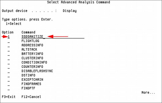
Figure 8-33 Selecting the SSDSANITIZE macro
7. Press the Enter key twice and a help panel is displayed, as shown in Figure 8-34.

Figure 8-34 SSDSANITIZE macro help panel
The sanitizing SSD units function is nearly identical to sanitizing HDD units from a user interface perspective.
To enable this function, the following PTFs are required:
•IBM i 7.1: MF52834
•IBM i 6.1.1: MF50873
•IBM i 6.1.0: MF50875
..................Content has been hidden....................
You can't read the all page of ebook, please click here login for view all page.