

Networking enhancements
This chapter describes the following topics that are related to networking enhancements enabled in IBM i 7.1:
•System SSL support for transport layer security version 1.2, OCSP support
9.1 TCP/IP enhancements summary
The following sections summarize the key TCP/IP enhancements in IBM i 7.1. These enhancements include the following topics:
•Additional TCP/IP application enablement for IPv6
•ISC-based DHCP server
•Enhancements in HTTP adding support for FastCGI PHP processing
•TELNET client SSL enablement
•Addition of SNMP version 3 (SNMPv3) support
•IKEv2
•Several new sockets programming user exits
9.1.1 IPv6 support enhancements
Although support for IPv6 was first introduced in IBM i 5.4, it existed primarily at the user application socket level. In IBM i 6.1, many of the standard IBM applications were enhanced to support either Internet Protocol version 4 (IPv4) or version 6 (IPv6). For more information, see 9.7, “IPv6 TCP/IP applications and V6R1 enablement PTFs” on page 441.
IBM i 7.1 extends this support by adding IPv6 for the following applications:
•DHCP Server
•DHCP Client
•SNMP
•SMTP
•PPP
9.1.2 ISC-based DHCP server supports IPv6 and failover
With IBM i 7.1, you have the option of using the new DHCP server that is based on the open source code that is provided by the Internet Systems Consortium (ISC). Existing customers can continue to use the old DHCP server that is supplied by IBM in previous releases or replace it with the ISC-based version.
The ISC-based server has several advantages. In addition to supporting IPv4, it also supports IPv6 and DHCP server failover. The DHCP server attributes can be set to run either an IPv4 or IPv6 server or both. There is no GUI support for managing the ISC DHCP server configuration files or for monitoring leases, such as with the old DHCP server. Therefore, by default, the old DHCP server is used.
If you want use the ISC DHCP server, you must add the QIBM_ISC_DHCP environment variable, as described in “Using the ISC DHCP IPv6 server on IBM i” on page 427. Then, stop your DHCP server by running the ENDTCPSVR command (if it is running) and start the ISC DHCP server with the STRTCPSVR command. The IBM i activation code attempts to migrate the old configuration file to the new ISC configuration file the first time that DHCP-related code is run (through CHGDHCPA or STRTCPSVR). The old configuration file is left unchanged after the migration. Any changes that are made to the old configuration file are not moved to the new one after the initial migration. The new configuration file might require editing to operate properly. The current leases file is also migrated to the ISC leases file. The migration is just a way to get started with the new server. Certain functions that are provided by the old server are not available with the ISC server, so you must weigh the benefits and differences between these two servers and choose which one is best for your environment.
If you want to switch back to the old DHCP server, delete the environment variable, or set the value to 'N', and then stop and restart the DHCP server. If the ISC DHCP server assigned any IP addresses when it was running, those leases are not available to the old DHCP server. There is no backward migration.
Using the ISC DHCP IPv6 server on IBM i
DHCP moved from the base OS to 5770-SS1 Option 31 and requires that 5770-SS1 Option 33 be installed. To use the ISC DHCP IPv6 server on IBM i, complete the following steps:
1. Ensure that IBM i option 31 (Domain Name System (DNS)) and option 33 (Portable Application Solutions Environment (PASE)) are installed on the system.
2. Define an environment variable to tell the operating system to use the ISC DHCP server by running the following command:
ADDENVVAR ENVVAR('QIBM_ISC_DHCP') VALUE('Y') LEVEL(*SYS)
3. Run the Change DHCP Attributes (CHGDHCPA) command.
This command migrates any existing DHCP configuration into the configuration files that are used by the ISC DHCP server. Determine if you want to run an IPv4, IPv6, or both. This setting is managed by setting the DHCP attribute for IPVERSION. The *ALL special value enables support for both IPv4 and IPv6.
CHGDHCPA IPVERSION(*IPV6)
4. Edit the newly created configuration files.
|
Access to the ISC DHCP server: A graphical interface is not provided for managing the ISC DHCP server and monitoring the leases that it manages. All associated configuration files must be edited manually.
|
There are several considerations to make when migrating from the existing IBM i DHCP server to the ISC DHCP server. For example, IBM Navigator for i does not provide an interface for configuring the ISC DHCP server in IBM i 7.1. To configure the ISC DHCP IPv6 server, edit the /QIBM/UserData/OS400/DHCP/ETC/DHCPD6.CONF configuration files manually. Example 9-1 shows an example.
Example 9-1 Edited configuration file
authoritative;
subnet6 1ffe:31::/64 {
default-lease-time 120;
max-lease-time 86400;
range6 1ffe:31::d0:ca1 1ffe:31::d0:cef;
}
Copy the above into /QIBM/UserData/OS400/DHCP/ETC/DHCPD6.CONF.
Make sure that you have at least one line that is enabled for IPv6 on your system and configured with an IPv6 address, for example something like: 1ffe:31::d0:ccc so that the line description of the address can be listened and that subnet6 would not be ignored.
Two more files might need to be configured depending on your configuration requirements:
•/QIBM/UserData/OS400/DHCP/ETC/DHCRELAY6.CONF
•/QIBM/UserData/OS400/DHCP/ETC/DHCPD6.LEASES
For further information, there are Linux / AIX man pages available for the ISC DHCP server and books such as The DHCP Handbook, by Drom, et al, which provides detailed descriptions for the configuration statements available. ISC also has information at the following web page:
9.1.3 DHCPv6 client
The DHCPv6 client is also new in IBM i 7.1. It is not explicitly configured, but is enabled by adding and starting a *IP6SAC interface as follows:
ADDTCPIFC *IP6SAC LIND(line-name)
The system tries to acquire only IPv6 addresses through DHCPv6 if an IPv6 router on the link tells the system (by turning on the 'M' bit in the Router Advertisement flags) to use the managed configuration to obtain IP addresses. The DHCPv6 client sends multicast messages to find a DHCPv6 server and to request IPv6 address assignment. The DHCPv6 server sends a reply with the addresses assigned. IP addresses obtained from the DHCPv6 server have a preferred and valid lifetime, just like stateless auto configured addresses. Before the preferred lifetime expires, the DHCPv6 client renews the addresses. When the *IP6SAC interface is ended, any DHCP addresses are released.
If the Privacy Extension parameter is enabled on the *IP6SAC interface, you also request temporary addresses from the DHCPv6 server. The request for temporary addresses is sent separately from the request for non-temporary addresses. Temporary addresses are never renewed; when the preferred lifetime is about to be reached, you request new temporary addresses. The old temporary addresses remain until either their valid lifetime is reached or the *IP6SAC interface is ended. The preferred and valid lifetime of DHCP temporary addresses is limited by the IPv6 temporary address valid and preferred lifetimes that are configured through CHGTCPA.
To identify itself to the DHCPv6 server, the client uses a DHCP Unique Identifier (DUID). This DUID is generated automatically from a MAC address on the system and a time stamp, and is saved by the TCP/IP configuration. This identifier is a system-wide identifier; the same DUID is used by DHCP on all lines. To identify separate lines, the DHCP message also contains an identity association identifier (IAID), which is a unique value for each separate line (generated and saved by the TCP/IP configuration). The current DUID can be viewed by using the CHGTCPA command. The value cannot be changed by the user, but the user can force generation of a new DUID if necessary, by using the *GEN option.
As with the DHCPv4 client, more configuration information can be obtained from the DHCPv6 server beyond just addresses. For DHCPv6, it supports the DNS Server List and Domain Search List options and adds received DNS servers and domains to the configuration when the DHCPv6 client is active.
Additionally, DHCPv6 supports an option to receive configuration information without allocating addresses. This option is automatically selected if the router on the link sends a router advertisement with the O flag (Other configuration) set rather than the M flag. In that case, you request just the DNS Server List and Domain Search List options from the
DHCPv6 server.
DHCPv6 server.
|
Support added: IBM i 6.1 added DHCPv4 client support for IPv4 with PTF SI31800.
|
9.1.4 SNMP
In release 7.1, the IBM i SNMP agent provides basic SNMP version 3 (SNMPv3) support. SNMP version 3 incorporates the use of user-based authentication and data privacy. The
IBM i 7.1 SNMP also includes support for IPv6. It is possible to configure SNMP manager IP addresses for both traps and communities through the CHGSNMPA and ADDCOMSNMP commands. IPv6 support for various MIBs, including RFCs 4022 and 4013, were added.
IBM i 7.1 SNMP also includes support for IPv6. It is possible to configure SNMP manager IP addresses for both traps and communities through the CHGSNMPA and ADDCOMSNMP commands. IPv6 support for various MIBs, including RFCs 4022 and 4013, were added.
Enabling the agent to handle SNMPv3 requests
To enable the agent to handle SNMPv3 requests, complete the following steps:
1. If the SNMP server is running, stop it by running ENDTCPSVR *SNMP.
2. Change the SNMP server attributes to allow version 3 by running CHGSNMPA ALWSNMPV3(*YES).
|
Supported functionality: The SNMP agent is still able to receive and handle packets and requests from older versions of SNMP v1 even after you change the SNMP attributes to specify ALWSNMPV3(*YES).
|
3. Check the engine identifier that is supplied by the SNMP Agent after it is started for the first time after ALWSNMPV3(*YES) is set.
In most cases, this engine identifier does not need to be changed. If the generated engine ID must be changed, do so by running CHGSNMPA. However, there are caveats. The engine identifier is created using a vendor-specific formula and incorporates the IP address of the agent. Any engine identifier that is consistent with the snmpEngineID definition in RFC 3411 and that is also unique within the administrative domain can be specified.
For example, the identifier 80000002010A010203 is a valid engine ID for an IBM i agent with an IP address of 10.1.2.3. The first byte, '80'X, indicates that the engine ID complies with the architecture defined in RFC 3411. The next four bytes, '00000002'X, indicate the private enterprise number for IBM as assigned by the Internet Assigned Numbers Authority (IANA). The next byte, '01'X, indicates that the remaining portion of the engine ID is an IPv4 address. The last four bytes, '0A010203'X, is the hexadecimal representation of the IP address. The CHGSNMPA SNMPENGID('80000002010A010203') command is run to specify the engine ID.
|
Important: An invalid SNMP engine ID can prevent an SNMP manager from communicating with the agent.
Important: Another new SNMPv3 parameter, SNMPENGB, was added to the CHGSNMPA command, and is the SNMP engine boots counter. Do not manually change this parameter unless you must reset it to a value of zero. This parameter indicates the number of times that the SNMP engine (agent) was started. Each time the STRTCPSVR *SNMP command is successfully run, this value increments automatically. Changing the SNMPENGB parameter when the agent is active can cause SNMPv3 authentication failures.
|
4. Add an SNMP user using the Add User for SNMP command, with encryption and privacy options that match your SNMP manager.
An SNMP user is not the same as an IBM i user profile. SNMP users must be added and maintained separately. For example, the following command adds an SNMP user who requires authentication using the HMAC-SHA authentication protocol and privacy using the CBC-DES encryption protocol:
ADDUSRSNMP USRNAME(testuser) AUTPCL(*HMACSHA) AUTPWD(authpassword) PVYPCL(*CBCDES) PVYPWD(privpassword)
The USRNAME, AUTPWD, and PVYPWD parameters are case-sensitive, so take care when you add SNMP users. The output of the ADDUSRSNMP is an entry in the SNMPv3 configuration file.
The configuration file /QIBM/USERDATA/OS/SNMP/SNMP.CONF contains the SNMP user information and their generated keys. The passwords that are specified are not stored.
The SNMP_USER statements in the configuration file are never edited manually. Instead, the ADDUSRSNMP, CHGUSRSNMP, and RMVUSRSNMP commands are used for maintaining the SNMP users. The CFGTCPSNMP command can be run to display and maintain the list of
SNMP users.
SNMP users.
5. Start the SNMP server by running STRTCPSVR *SNMP.
6. Start an SNMPv3 manager application and configure it for the SNMP user that was added in step 4.
|
Support of functionality: The IBM i 7.1 SNMP manager APIs snmpGet, snmpSet, and snmpGetnext do not support SNMPv3, so a non-native manager such as a PC-based manager must be used. There are a number of these managers available for download, including both no-cost and for-purchase options.
|
Resolving time synchronization errors
When an SNMPv3 manager first communicates with an SNMPv3 agent, it goes through a discovery process that involves the determination of the agent's SNMP engine ID and SNMP engine boot values. It addition, time synchronization occurs. These steps are necessary before you do any actual SNMP operations, such as Get or GetNext. If you have problems with these initial steps, the SNMP manager can indicate that a time synchronization error occurred. If this error occurs, complete the following steps:
1. Stop the SNMP agent and manager.
2. Run the following command:
ADDENVVAR ENVVAR('QIBM_SNMPV3_AUTH') VALUE('1') LEVEL(*SYS)
3. Restart the SNMP agent and manager and try the request again.
9.1.5 SMTP
IPv6 support was added in IBM i 7.1. Currently, there is no IPv6 standard for Real-time Black holes Lists (RBL). The RBL works only for IPv4 addresses. SMTP uses the getaddrinfo() API to look up email DNS records. They are looked up first as IPv6 and then as IPv4, which is different from what RFC 3974 recommends. Parts of the DNS resolver were fixed in IBM i 7.1 to be more correct.
SMTP support for RFC 821 and RFC 822 were removed. Starting in IBM i 7.1, Simple Mail Transfer Protocol (SMTP) supports only RFC 2821 and 2822. RFC 2821 and RFC 2822 deprecate many parts of the RFC 821 and RFC 822 email standards. Behavior for SMTP routes, SMTP alias shadowing, and processing mail through Mail Service Framework (MSF) are not compatible with the RFC 2821 and RFC 2822 standards, and are to be used on an as is basis. The first part of a source route is still honored from RFC 821; other parts of the source route are not contacted. The absolute address is the best way to send email.
The MAILROUTER feature before IBM i 7.1 can, in instances, forward all mail to the mail router even if the email address can be resolved. In IBM i 7.1, MAILROUTER correctly forwards to the mail router only when the email address does not resolve.
The FWDMAILHUB feature was added in IBM i 6.1, and allowed the forwarding of email to a single address. FWDMAILHUB always forwards the email and does not attempt a resolve.
MAILROUTER supports only A and AAAA records, when FWDMAILHUB supports MX, CNAME, AAAA, and A.
The resolve path is shown in Example 9-2.
Example 9-2 Resolve path
Forwarding Mail hub(if defined)->
Absolute Address/First part of source route->
mailrouter(if same domain)->
mailrouter(different domain) if FIREWALL(*YES).
9.1.6 Async adapter expanded IBM i support
IBM i 7.1 TR7 delivers PPP support to the existing 2-port asynchronous communications adapter, the PCIe 2-Port Async EIA-323 Adapter (#5289 and #5290). Previously, IBM i 7.1 TR5 had provided non-PPP support for POWER7/POWER7+ servers. Non-PPP enables connecting with async terminals, workstations, printers, manufacturing devices, time clocks, handling faxes, and pagers. PPP enables applications such as IBM Electronic Customer Support (ECS), IBM Electronic Service Agent™ (ESA), and the IBM iGSC Remote support tool.
The IBM i 2-port communications adapter (#2893/#2894 with CCIN 576C) remains available to enable bisync support for those clients who still use this older protocol and to support MES orders for POWER5/POWER6 servers.
Communication ports are not virtualized by IBM i. IBM i 7.1 does not virtualize the adapter for other IBM i partitions, nor does VIOS virtualize async ports for other partitions.
9.1.7 IPv6 support added for PPP connections
Starting in IBM i 7.1, Point-to-Point (PPP) can support both IPv4 and IPv6 addresses. A PPP connection profile can have only IPv4 enabled, only IPv6 enabled, or both IPv4 and IPv6 enabled. By default, both IPv4 and IPv6 are enabled for a PPP connection profile.
Note the following items:
•IPv6 can be enabled in connection profiles to allow remote workers to use IPv6 to access the company network.
•If your ISP supports IPv6 addressing, you can also enable IPv6 in the originator profile.
•If the Enable IPv6 check box is checked in the TCP/IP IPv6 Settings section of a connection profile, then when the connection profile is activated, IPv6 Stateless Address Auto configuration assigns an IPv6 link-local address to the PPP link. In many cases, this configuration is all that is required to use IPv6 over a PPP link.
•More IPv6 configuration options are available if IP forwarding is enabled in the TCP/IP IPv6 Settings section of a connection profile. Enabling IPv6 datagram forwarding also enables the system to run router functions for this link, including sending Router Advertisement messages and responding to Router Solicit messages.
Figure 9-1 highlights the configuration changes that are required to enable IPv6 for a connection profile.
|
Feature availability: PPP configuration enhancements for IPv6 are only available using IBM Navigator for i. It is not available using the PC-based client System i Navigator.
|
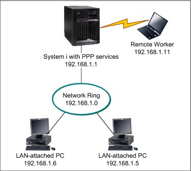
Figure 9-1 Traditional IPv4 PPP remote access configuration
If you want your remote workers to use IPv6 to access the company network, you must enable IPv6 in the connection profile. You do not need to assign a specific IPv6 address. However, if you want the remote workers to have more than the default link-local IPv6 address assigned, you must either configure an IPv6 address prefix or set the appropriate options if a DHCPv6 server is available in the company network.
For this example, assume that you want to advertise an address prefix of 2001:DBA::, a default route, and that a DHCPv6 server in your network can provide IP addresses. A global IPv6 address must be configured in the connection profile to allow the DHCPv6 server to return information to the remote dial-in client. This address can be configured in the Receiver Connection Profile using IBM Navigator for i, as shown in Figure 9-2.
Click Network → Remote Access Servers → Receiver Connection Profiles, and in the right pane, click Action → New Profile.
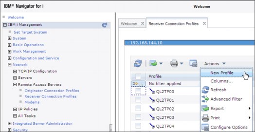
Figure 9-2 Create a Receiver Connection Profile
Select Protocol type, Connection type, and Link configuration for the new profile, and click OK, as shown in Figure 9-3.
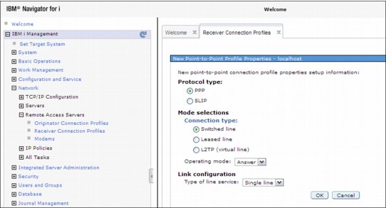
Figure 9-3 Select parameters for the new profile
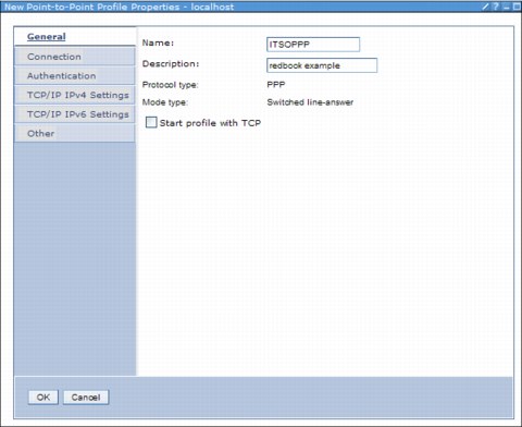
Figure 9-4 PPP - Create Receiver Connection profile window with the IPv6 option
To advertise an address prefix of 2001:DBA::, a default route, and that a DHCPv6 server in your network can provide IP addresses, configure a global IPv6 address in the connection profile as follows (see Figure 9-5 on page 435):
1. Select Enable IPv6.
2. Specify a global IPv6 address for Fixed local IP address. This address must be compatible with the DHCPv6 server configuration for distributing IPv6 addresses. For this example, click None.
3. Click Generate for the Interface identifier field.
4. Select Yes for the Allow remote system to access other networks (IP forwarding) check box.
5. Set the Address prefix to 2001:DBA::.
6. Select Advertise IPv6 default route.
7. Select Advertise DHCPv6 and Managed address configuration.
8. Click OK to complete the profile.

Figure 9-5 Configure PPP IPv6 preferences
9.2 HTTP server support for PASE FastCGI PHP processing
FastCGI is an open standard that extends the Common Gateway Interface (CGI) standard that is supported by many common web servers today. This standard defines how information is exchanged between a web server and FastCGI programs that are isolated in external processes. On IBM i 7.1, these external processes are provided by a FastCGI Apache module that makes external PASE programs (FastCGI programs) available as CGI jobs. These jobs can then be used by the native ILE environment, which results in faster HTTP request processing.
Further implementation details are available at:
Software updates that enable FastCGI PHP Processing in IBM i 6.1 were also included in the HTTP Group PTF package for January 2010.
The required components and PTF information for 6.1 is shown in 9.2.1, “IBM i 6.1 required components” on page 435.
9.2.1 IBM i 6.1 required components
This section lists the IBM i 6.1 required components:
•Products
– 5761SS1 30 Qshell (only needed to create CCSID 819 files)
– 5761SS1 33 Portable App Solutions Environment
– 1ZCORE5 *BASE Zend Core for IBM i (Version 2.6.1 or later) (only for FastCGI PHP support)
– 5761DG1 *BASE IBM HTTP Server for i
– 5761DG1 1 IBM HTTP Server for i
– 5733SC1 *BASE IBM Portable Utilities for i (only for FastCGI PHP support)
•PTFs
– SI36005 (PASE) SI36027 (DG1)
– Group PTFs: SF99115: 610 IBM HTTP Server for i (PTF Group Level: 10 or later)
9.3 Telnet client support for SSL encryption
Although the Telnet server for IBM i has long supported SSL for remote clients, IBM i 7.1 can support SSL as a client. This capability was also enabled for IBM i 5.4 and 6.1 through PTFs, and activated using the QIBM_QTV_TELNET_CLIENT environment variable. With this new feature enabled, the TELNET command can now connect to a remote telnet server that supports implicit SSL/TLS.
The PORT parameter of the TELNET command prompt was moved to a new location in the parameter string, and a new parameter, Secure Connection (SSL), was added to the command format. If the environment variable was set up for a secure connection, or the SSL(*YES) parameter is selected, the target port number defaults to 992.
The requirements are as follows:
•You must have the Digital Certificate Manager (5770-SS1 Option 34) installed.
•You must have certificates that are set up for the client application QIBM_QTV_TELNET_CLIENT. Either a trust list or the remote server certificates must be assigned to this application. The trust list must have the certificate authorities of the wanted remote servers added.
If you want all telnet client users on your system to use SSL, set the QIBM_TELNET_CLIENT_SSL as a system level environment variable.
Encryption is provided by using either SSL or Transport Layer Security (TLS) based on negotiation between the Telnet client and the server.
The TELNET client must be assigned an appropriate certificate in the Digital Certificate Manager (DCM) or the connection fails. See Figure 9-6.
|
Start TCP/IP TELNET (TELNET)
Remote system . . . . . . . . . RMTSYS
Internet address . . . . . . . . INTNETADR
Port . . . . . . . . . . . . . . PORT *DFT
Secure connection . . . . . . . SSL *ENVVAR
|
Figure 9-6 New parameter of the STRTCPTELN command for SSL enablement
|
PTF support: This enhancement was made available for V5R4 and V6R1 through the following PTFs:
•V5R4 - SI32220
•V6R1 - SI32527
|
9.4 System SSL support for transport layer security version 1.2
IBM i 7.1 Secure Sockets Layer (SSL) now supports the latest industry standards of Transport Layer Security version 1.2 (TLSv1.2) and Transport Layer Security version 1.1 (TLSv1.1) protocols. The TLSv1.2 protocol uses SHA2 hashing algorithms. System SSL also supports the Online Certificate Status Protocol (OCSP) during the certificate validation process. OCSP is used for checking the revocation status of end entity certificates.
Digital Certificate Manager (DCM) options on the Application Definition configuration panels allow many of the core IBM networking applications (Telnet, FTP, and so on) to use these new protocols and to enable OCSP. Applications using a system SSL programming interface or the Global Secure Toolkit (GSKit) system SSL programming interface can switch to the new protocols by making changes to the code and recompiling.
Following are the prerequisites for this support:
•5770SS1 option 34 - Digital Certificate Manager must be installed
•PTF 5770-SS1 SI48659 must be installed
•PTF 5770-SS1 SI48539 must be installed
New TLSv1.1 and TLSv1.2 support allows set up by changing the QSSLPCL system variable; then applications must be configured in DCM to use specific versions of TLS and ciphers suites.
More on this topic can be found at the following website:
Also, see the DCM Application Definitions topic in the IBM i Knowledge Center:
9.5 Sockets programming: New user exits
Functional enhancements to sockets programming include three sockets-related user exit points. These enhancements were added to give a user-defined exit program the ability to control connections that are based on specific runtime characteristics. User-defined exit programs that are registered with the exit points defined in the user registry are able to limit incoming and outgoing connections.
9.5.1 Exit points that are defined in the user registry
User-defined exit programs that are registered with the exit points defined in the user registry are able to limit incoming and outgoing connections. The return codes of the user-defined exit programs indicate whether to allow successful completion to connect(), listen(), accept(), accept_and_recv(), or QsoStartAccept(). See Table 9-1.
Table 9-1 User exit points
|
User exit point
|
Description
|
|
QIBM_QSO_ACCEPT
|
Enables a custom exit program to allow or deny incoming connections that are based on the restrictions that are set by the programs.
|
|
QIBM_QSO_CONNECT
|
Enables a custom exit program to allow or deny outgoing connections that are based on the restrictions that are set by the programs.
|
|
QIBM_QSO_LISTEN
|
Enables a custom exit program to allow or deny a socket the ability to listen for connections that are based on the restrictions that are set by the programs.
|
|
Sockets APIs considerations:
•By default, the sockets APIs accepting connections silently ignore rejected connections and wait for the next incoming connection. To give an application the ability to be informed about rejected connections, a socket option is provided. The socket option is enabled by setsockopt() with a level of SOL_SOCKET and option name SO_ACCEPTEPERM. When the socket option is enabled, sockets APIs accepting connections fail with EPERM for each incoming connection that is rejected by the user exit program that is registered for QIBM_QSO_ACCEPT.
•Any user that tries to add or remove a sockets-related user exit program is required to have *IOSYSCFG, *ALLOBJ, and *SECADM authority.
|
9.5.2 Example: User exit program for QIBM_QSO_ACCEPT
This section illustrates an example of the user exit program for the QIBM_QSO_ACCEPT user exit point.
The program in Example 9-3 rejects all incoming connections to the Telnet server that come from a particular remote IP address between the hours of 12 a.m. - 4 a.m. The program determines whether the incoming connection can be accepted by the socket API accepting connections or will be rejected.
Example 9-3 Socket program example using the QIBM_QSO_ACCEPT user exit
/******************************************************************/
/* System i - Sample User Exit Program for QIBM_QSO_ACCEPT */
/* */
/* Exit Point Name : QIBM_QSO_ACCEPT */
/* */
/* Description : The following ILE C language program */
/* will reject all incoming connections to */
/* the telnet server (port 23) coming from */
/* the remote IP address of '1.2.3.4' between */
/* the hours of 12 A.M. and 4 A.M. */
/******************************************************************/
#include stdio.h
#include string.h
#include esoextpt.h /* Exit program formats */
int main(int argc, char *argv[])
{
Qso_ACPT0100_Format input; /* input format */
struct in_addr addr;
char return_code;
/****************************************************************/
/* Initialize the address to compare to 1.2.3.4 */
/****************************************************************/
addr.s_addr = 0x01020304;
/****************************************************************/
/* By default allow the connection. */
/****************************************************************/
return_code = '0';
/****************************************************************/
/* Copy format parameter to local storage. */
/****************************************************************/
memcpy(&input, (Qso_ACPT0100_Format *) argv[1],
sizeof(Qso_ACPT0100_Format));
/****************************************************************/
/* If the local port is the telnet server */
/****************************************************************/
if((input.Local_Incoming_Address_Length == sizeof(sockaddr_in) &&
input.Local_Incoming_Address.sinstruct.sin_port == 23) ||
(input.Local_Incoming_Address_Length == sizeof(sockaddr_in6) &&
input.Local_Incoming_Address.sin6struct.sin6_port == 23))
{
/**************************************************************/
/* And the incoming connection is from 1.2.3.4 */
/**************************************************************/
if(input.Remote_Address_Length == sizeof(sockaddr_in) &&
(memcmp(&input.Remote_Address.sinstruct.sin_addr,
addr, sizeof(struct in_addr)) == 0))
{
/************************************************************/
/* And the time is between 12 A.M. and 4 A.M. */
/* Reject the connection. */
/************************************************************/
if(IsTimeBetweenMidnightAnd4AM())
return_code = '1';
}
}
*argv[2] = return_code;
return 0;
}
|
Important: By using the example that is shown in Example 9-3 on page 438, you agree to the terms of the code license and disclaimer information that is available at:
|
9.6 IKEv2 support
You can now use the enhanced IKE version 2 when you run dynamic key connection. Enhanced Cryptographic Algorithms are also available for use with VPN key exchange policy and data policies. Existing objects were used as much as possible to enable either IKEv1 or IKEv2 exchanges. This design was used to minimize the impacts to the current GUI interface and VPN configuration objects when you enable IKE version 2. See Figure 9-7.
Note the following items:
•To enable IKEv2, an IKE Version setting is provided on the Dynamic Connection definition.
•Key Exchange policies can be used for either IKEv1 or IKEv2.
•There are no more differences to other attributes, such as Key Exchange policy identifiers (all are still supported) and transforms.
•Main mode / aggressive mode settings are ignored if the Key Exchange Policy is used for IKEv2.
•Systems IBM Navigator for i is required to configure an IKEv2 connection.
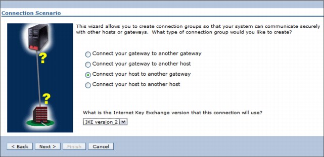
Figure 9-7 Internet Key Exchange V2 enablement for VPN
9.6.1 Enhanced Cryptographic Algorithms
Enhanced Cryptographic Algorithms were added to IBM i 7.1.
Key exchange policy
Note the following items for the key exchange policy:
•Encryption: AES-CBC – 128 bits
•Hash/PRF
– AES-XCBC-MAC (HASH 96 bits; PRF 128 bits)
– HMAC-SHA-256
•Diffie-Hellman
– Group 14
– Group 24
Data policy
Note the following authentication items for the data policy:
•AES-XCBC-MAC
•HMAC-SHA-256
Diffie-Hellman for PFS
Note the following items for Diffie-Hellman for PFS:
•Group 14
•Group 24
For more information and configuration details, see the Virtual Private Networking, available at:
9.7 IPv6 TCP/IP applications and V6R1 enablement PTFs
Support for IPv6 is being added incrementally to TCP/IP applications and protocols for the IBM i operating system. The following Knowledge Center entry provides a complete list of which applications and protocols that support IPv6 in IBM i 6.1 and 7.1:
This website is updated as PTFs are made available for more applications or protocols. As of this publication, the following list identifies IBM i 6.1 applications and protocols that support IPv6:
•IBM Online Help and Eclipse Knowledge Center (IBMHELP) - PTF SI31014
•INETD - PTF SI29701
•SNTP - PTF SI30112
•TFTP - PTF SI30868
•LPD - PTF SI31015
•Remote Journal - PTF SI31713
•Remote Journal - PTF MF44589
•IPP printer driver - PTF SI31910
•LPR and Remote output queues - PTF SI31363
•Enterprise Extender 1 (MSCP) - PTF MF44318
•Enterprise Extender 2 (HPR) - PTF MF44355
•Enterprise Extender 3 (HPR) - PTF MF44356
•Enterprise Extender 4 (DC) - PTF SI31250
•Enterprise Extender 5 (SW) - PTF SI31223
•Enterprise Extender 6 (Comm Trace) - PTF SI30790
•Management Central - PTF SI31888
•Management Central - PTF SI31892
•Management Central - PTF SI32720
•Management Central - PTF SI32721
9.8 IBM AnyNet support on IBM i 7.1
Enterprise Extender was introduced with IBM i 5.4 and was identified then as the strategic direction for replacing IBM AnyNet®. Although AnyNet was removed in IBM i 7.1, IBM stated that there are no further enhancements beyond IBM i 6.1 and IBM no longer offers support for it on 7.1.
The IBM i 7.1 Knowledge Center topic “Migrating from IBM AnyNet to Enterprise Extender” provides detailed migration considerations and requirements, and is available at:
9.9 Ethernet link aggregation
The following sections describe the IBM i Ethernet link aggregation function available in
IBM i 7.1:
IBM i 7.1:
9.9.1 Overview of Ethernet link aggregation
Link aggregation binds several full-duplex Ethernet links that run at the same speed together into one logical link with a single Media Access Control (MAC) address. This aggregation is known by several other names, including IEEE 802.3ad or 802.1ax, Cisco Etherchannel, or the names teaming or trunking.
With the Ethernet link aggregation function available in IBM i 7.1, up to eight Ethernet links can be bound together in a single-line description.
The advantages of this function are:
•Simplified redundancy and reliability
By binding multiple Ethernet links to a single-line description, if a link fails, the others remain active and the network load is rebalanced across the active links without requiring any system or network administrator actions.
Before this function, if a line failed, IP configuration changes and a manual switch to another line description and link were required.
•Capacity
By aggregating multiple links to a single-line description, outgoing traffic is spread across the links as determined by a user-selected policy and incoming traffic by a policy that is configured at the network switch. This configuration also enables more capacity for a certain IP address.
For example, two aggregated 1 Gbps links can carry up to 2 Gbps for the same IP interface without any additional configuration.
9.9.2 Prerequisites for Ethernet link aggregation
To use Ethernet link aggregation, the environment must have:
•Up to eight Ethernet ports, 10 Gbps or 1 Gbps-capable, on an IBM i partition not in use for other purposes.
•The ports must be on the same network switch and be in a static configuration.
•The newest IBM i 7.1 Technology Refresh PTF and PTF Group (SF99707).
•A Cisco Catalyst switch with an aggregate in Etherchannel mode that is enabled for
static configuration.
static configuration.
|
Unsupported switches: Other switches that support static aggregation configurations might also work, but they were not tested and are not officially supported.
|
9.9.3 Configuring Ethernet link aggregation
The following steps are used to configure Ethernet line aggregation. See the example command in Figure 9-8.
|
Create Line Desc (Ethernet) (CRTLINETH)
Type choices, press Enter.
Line description . . . . . . . . > TESTLINE Name
Resource name . . . . . . . . . > *AGG Name, *AGG, *NWID, *NWSD
Bridge identifier . . . . . . . *NONE Name, *NONE
Online at IPL . . . . . . . . . *YES *YES, *NO
Vary on wait . . . . . . . . . . *NOWAIT *NOWAIT, 15-180 seconds
Aggregate policy:
Standard . . . . . . . . . . . > *LNKAGG *ETHCHL, *LNKAGG
Policy type . . . . . . . . . > *RNDRBN *DFT, *SRCPORT, *DESTPORT...
Aggregated resource list . . . . > CMN01 Name
+ for more values > CMN02
Attached NWI . . . . . . . . . . *NONE Name, *NONE
NWI type . . . . . . . . . . . . *FR *FR
DLC identifier . . . . . . . . . *NONE 1-1018, *NONE
Network server description:
*NONE Name, *NONE
Port number . . . . . . . . . 1-2, *VRTETHPTP, *VRTETH0...
More...
F3=Exit F4=Prompt F5=Refresh F12=Cancel F13=How to use this display
F24=More keys
|
Figure 9-8 Creating an Ethernet line description with Link Aggregation Control Protocol
1. The Create Line Desc (Ethernet) (CRTLINETH) and Change Line Desc (Ethernet) (CHGLINETH) commands are used to manage Ethernet line descriptions, including aggregate line descriptions (indicated by Resource name (RSRCNAME) *AGG). For an aggregate line description, the Aggregate policy (AGGPCY) has two elements:
– Standard, which controls negotiation with the link partner, usually a switch
– Policy type, which controls which Ethernet port is used to send each outgoing frame
Before IBM i 7.1 TR7, only static aggregation was supported, with the documentation stating that the standard must be set to *ETHCHL. With TR7, IBM i adds support for the Link Aggregation Control Protocol (LACP) with the *LNKAGG option. For environments that support it, LACP offers two key benefits of detection and tolerance of incorrect configurations (like invalid cabling or link partner settings) and easier switch configuration.
Specifying *ETHCHL as the standard uses static aggregation, which does no negotiation with the link partner. The link partner must also be configured for static aggregation. The Ethernet ports in the Aggregated Resource List (AGGRSCL) and the set of ports configured at the link partner should correspond exactly. If they do not, some Ethernet packets might not get to the correct destination.
There are several opportunities for error:
– Having ports in AGGRSCL that are connected to a different link partner or to the wrong ports in the correct link partner.
– Having ports selected in the link partner's aggregate that are connected to ports not in AGGRSCL.
The second element specifies the Policy type. Here are the allowed special values and their meanings:
– *DFT: The adapter selection algorithm uses the last byte of the Destination IP address (for TCP/IP traffic) or MAC address (for ARP and other non-IP traffic). This mode is typically the best initial choice for a server with many clients.
– *SRCPORT: The adapter selection algorithm uses the source TCP/IP or UDP port value.
– *DESTPORT: The outgoing adapter path is selected through an algorithm using the destination TCP/IP or UDP port value.
– *SRCDESTP: The outgoing adapter path is selected through an algorithm using the combined source and destination TCP or UDP port values.
– *RNDRBN: Outgoing traffic is spread evenly across all the adapter ports in the Etherchannel. This mode is the typical choice for two hosts connected back-to-back (that is, without an intervening switch).
Specifying *LNKAGG forces the use of the Link Aggregation Control Protocol (LACP) as described in the IEEE 802.3ad standard. This negotiation detects the identity of the link partner for each Ethernet port in the Aggregated Resource List (AGGRSCL). This process requires that the link partner enable LACP with common identification information about all ports that are connected to ports in AGGRSCL. In order for a port to aggregate and be used for Ethernet traffic, its partner port must respond to the LACP negotiation, and the response must match the identifying information to all other aggregated ports. The aggregation panel in Display Line Description (DSPLIND) shows the aggregation status of each port. For any port that has not joined the aggregate, the status should help determine why.
2. Choose a list of the communication resources that should be aggregated and specify them in the Aggregated resource list parameter.
3. You must select a single speed for all of the adapters as specified in the Line speed parameter.
4. You must set the DUPLEX parameter to full-duplex (*FULL). Then, create the aggregated line description.
5. The corresponding ports on the switch must be bound together into an aggregate according to the switch's configuration manual. The configuration must indicate that all of the ports are always aggregated (as opposed to being negotiated according to some protocol).
9.9.4 Example: Configuring four aggregated network links
A logical view of another example is shown in Figure 9-9.
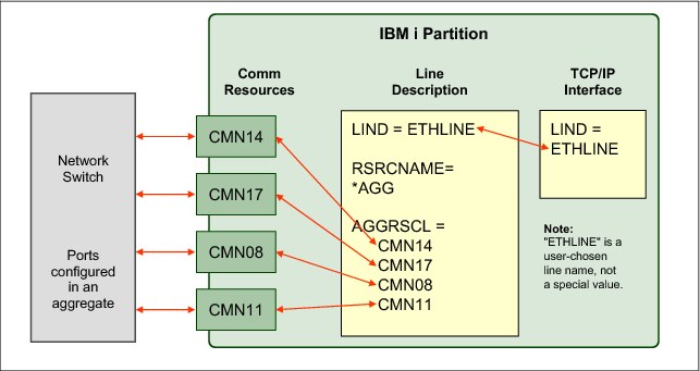
Figure 9-9 Logical view of example with four aggregated links
In the example, four links and IBM i communication resources (CMN14, CMN17, CMN08, and CMN11) are aggregated together with one line description named ETHLINE.
The command that is shown in Figure 9-10 creates the line description for the aggregated configuration.
|
CRTLINETH LIND(ETHLINE)
RSRCNAME(*AGG)
AGGPCY(*ETHCHL *RNDRBN)
AGGRSCL(CMN14 CMN17 CMN08 CMN11)
LINESPEED(1G)
DUPLEX(*FULL)
TEXT('Four link aggregated line')
|
Figure 9-10 Example CRTLINETH command for four aggregated links
For more information about configuring Ethernet resources and link aggregation, see the IBM i Knowledge Center at the following website. For Ethernet requirements, see the hardware requirements section.
9.10 Ethernet Layer-2 bridging
The following sections describe the sharing of physical Ethernet connections through Ethernet Layer-2 bridging using IBM i 7.1:
9.10.1 Introduction to Ethernet Layer-2 bridging
Logical partitions in a Power Systems system typically need access to an IP network, usually through Ethernet. However, it is not always possible or cost-effective to assign a physical Ethernet adapter to every logical partition in a Power Systems system.
One answer to this dilemma is the new Ethernet Layer-2 bridging function in IBM i 7.1. Although similar in concept to the Shared Ethernet Adapter (SEA) support provided by a Power Systems Virtual I/O Server (VIOS) partition, this IBM i function enables a single physical LAN connection to be shared by multiple logical partitions on a physical system without using Virtual I/O Server (VIOS).
With IBM i 7.1, an IBM i partition can bridge a physical Ethernet port to the virtual LAN. This function reduces costs in the following ways:
•Sharing an Ethernet port means fewer Ethernet cards on the server.
•Fewer ports are needed at the network switch and fewer cables are required.
•There might be reduced administration costs because there are fewer physical resources to manage.
•Complexity might be reduced because no Virtual I/O Server partition is needed to manage the port sharing.
9.10.2 How Ethernet Layer-2 bridging works on IBM i
Ethernet Layer-2 bridging on IBM i works as follows:
1. A single partition is defined to have a physical Ethernet adapter.
2. A bridge using the IEEE 802.1D standard is configured to link a virtual Ethernet LAN to the physical Ethernet adapter.
3. Frames that are transmitted by virtual Ethernet adapters on the same VLAN as the bridging virtual Ethernet adapter can be sent to the physical network.
4. Frames that are sent from the physical network can be received by adapters on the virtual network.
5. After the bridge is in place, other partitions can access the physical network by using virtual Ethernet adapters on the bridged virtual LAN.
A logical view of the Layer-2 bridging as implemented on IBM i is shown in Figure 9-11.
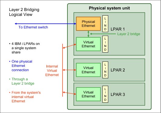
Figure 9-11 Ethernet Layer-2 bridging logical view on IBM i
9.10.3 IBM i prerequisites for Ethernet Layer-2 bridging
To use Ethernet Layer-2 bridging, you must have the following prerequisites in place:
•A partition with the newest IBM i 7.1 Technology Refresh PTF and PTF Group installed
•An unused10 Gbps or 1 Gbps-capable Ethernet adapter in the IBM i partition (excluding Host Ethernet Adapter logical ports)
•Access to the management console for the system, which can be either:
– The Hardware Management Console
– The IBM i Virtual Partition Manager
|
Tip: Use the selected Ethernet resources only for Layer-2 bridging and not for IBM i TCP/IP configuration, as there is a significant increase in processor usage for any host traffic that uses bridged resources.
|
9.10.4 Configuring a shared network connection through Ethernet Layer-2 bridging
To configure Ethernet Layer-2 bridging to share a network card, complete the following steps:
1. As the administrator, use the management console to create a virtual Ethernet adapter in the IBM i partition, indicating that the adapter is used for external access.
– Configuring a virtual adapter using a Hardware Management Console
If you are using a Hardware Management Console, click Systems Management → Servers → Configuration → Manage Profiles → Edit profile → Virtual Adapters to reach the window that is shown in Figure 9-12.
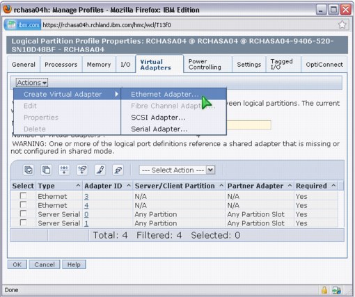
Figure 9-12 Select Create Virtual Adapter - Ethernet Adapter on an HMC
When you create the virtual Ethernet adapter, select the Access external network check box to indicate that this virtual Ethernet adapter is used to bridge traffic to the physical network, as shown in Figure 9-13.

Figure 9-13 Creating the virtual Ethernet adapter on an HMC
– Configuring a virtual adapter by using IBM i Virtual Partition Manager
If you are using the IBM i Virtual Partition Manager, the virtual Ethernet adapter is automatically created with the ability to access the external network. To create the adapter, go to the Change Partition Configuration panel by clicking STRSST → Work with system partitions → Work with partition configuration → Change. Create the virtual adapter by changing one or more of the virtual Ethernet identifiers to 1 (Yes), as shown in Figure 9-14.
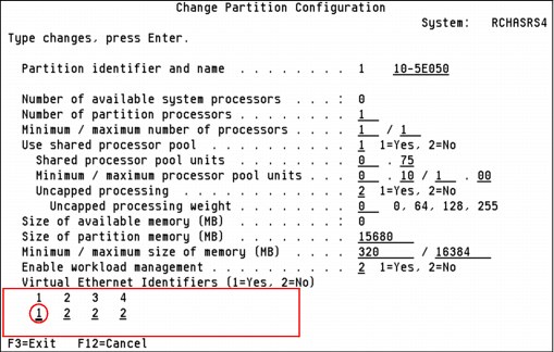
Figure 9-14 Virtual Partition Manager with virtual Ethernet ID1 activated
2. On the IBM i partition with the physical adapter, create two Ethernet line descriptions:
a. Create a one line description for the Ethernet link (physical communications resource CMN09) connected to the physical network, as shown in Figure 9-15.
|
CRTLINETH LIND(ETHLINEP) RSRCNAME(CMN09) BRIDGE(COVERED) LINESPEED(1G) DUPLEX(*FULL) TEXT('Line for physical Ethernet link')
|
Figure 9-15 Command to create line description for the physical link
b. Create a one line description for the new virtual Ethernet adapter (virtual resource CMN14), as shown in Figure 9-16.
|
CRTLINETH LIND(ETHLINEB) RSRCNAME(CMN14) BRIDGE(COVERED) LINESPEED(1G) DUPLEX(*FULL) MAXFRAME(8996) TEXT('Line for virtual Ethernet bridge')
|
Figure 9-16 Command to create the virtual line description for the bridge link
The resource name for a virtual adapter is found by selecting a CMNnn resource with type of 268C. Communications resources can be displayed through the Work with Hardware Resources (WRKHDWRSC) command by specifying the TYPE(*CMN) parameter.
3. To establish the bridge, the user gives the two line descriptions the same bridge name, which is a new parameter on the CRTLINETH and CHGLINETH commands for the purposes of this support. In the example commands above, the bridge name is “COVERED”.
4. When both line descriptions are active, traffic is bridged between the physical network and the virtual networks.
5. On any IBM i partition that uses the bridged connection, a line description must be created by specifying a virtual communications resource and the bridge name of “COVERED”. The command to do this task is shown in Figure 9-17.
|
CRTLINETH LIND(ETHLINVRT) RSRCNAME(CMNxx) BRIDGE(COVERED) LINESPEED(1G) DUPLEX(*FULL) MAXFRAME(8996) TEXT('Line for virtual Ethernet')
|
Figure 9-17 Command to create a virtual line description on another partition to use the bridge
For more information about configuring Ethernet resources and Layer-2 bridging, see the IBM i Knowledge Center at the following website address. For Ethernet requirements, see the hardware requirements section.
9.11 IBM Portable Utilities for i (5733-SC1) supported versions
License Program Offering 5733-SC1 - IBM Portable Utilities for i contains the OpenSSH, OpenSSL, and zlib open source packages that are ported to IBM i by using the PASE for i runtime environment.
For IBM i 7.1 and IBM i 6.1, the most current versions are listed along with their respective PTFs in Table 9-2.
Table 9-2 IBM Portable Utilities function, version, and PTFs
|
Function
|
Version
|
Version 7.1 PTFs
|
Version 6.1 PTFs
|
|
OpenSSH
|
4.7p1
|
SI38685, SI39965
|
SI40092
|
|
OpenSSL
|
0.9.8
|
SI41724
|
SI36892
|
|
zlib
|
1.2.3
|
None, in base
|
None, in base
|
..................Content has been hidden....................
You can't read the all page of ebook, please click here login for view all page.