
Chapter 6. 3D Animation
Here’s how the American Heritage Dictionary defines animation: “The act, process, or result of imparting life, interest, spirit, motion, or activity.” Motion. Activity. When you think about animation, you think about movement. Movement in animation is created with keyframes, and you might think that this should have been the first topic discussed in this book, given that LightWave is an animation program. However, knowing how to create an effect and understanding where to make the right adjustments saves you not only time but aggravation as well. Understanding timing is a constant in an animator’s career, and it’s also the focus of this chapter. As you know, 3D image creation isn’t always about movement, and regardless of whether you’re dealing with still or moving images, understanding the environment in which you are working is key to your success as an animator and 3D artist. There are so many facets to 3D animation—from modeling to texturing, lighting, and even scripting—that it’s sometimes a real headache trying to figure out where to start.
LightWave 10 is uncluttered yet very functional. Many programs fill up the screen with useless icons; thankfully, LightWave names buttons clearly. This enables you to focus on your creative goals instead of having to figure out what a particular icon means. Going one step further, LightWave’s powerful Graph Editor offers you complete control over a specific item’s motion and timing. This item can be a camera, an object, a light, or any other type of parameter that can be enveloped or changed over time. As I mentioned in Chapter 2, “LightWave Layout,” you’ll find those little E buttons throughout the LightWave interface. This chapter discusses what to do with those Es when you click them.
Note
You’ll find the E buttons next to the controls for attributes, such as Surface Color, that can be changed over time in the Graph Editor. Why E? A long time ago, in a galaxy far, far away (Topeka), LightWave was born with a tool called Envelope. (Technically, animating a motion channel is “enveloping” its values.) Envelope evolved into the Graph Editor but retained its ancestral initial. Here, you can animate just about any value or channel in LightWave. If you feel that the next version of LightWave should have “A” for animate rather than “E” for a nonexistent Envelope panel, email our friends at NewTek.
The Graph Editor that opens when you click an E button also gives you control over every channel of an item, such as the X position, heading rotation, dissolves, light color, and so on, all over a set duration. Each channel can be controlled through the use of expressions, modifiers, or even keyframes, all from within the Graph Editor. The Graph Editor is used to edit any type of parameter that can be enveloped or, as the nontechnical folk like to say, animated. In this chapter, you will learn about the following:
• Creating motion with keyframes
• Using motion splines
• Adjusting motions
• Working with the Graph Editor
Note
An expression is a LightWave function that lets you set specific operations based on mathematical statements. For example, you can select an animated wheel object and create an expression that tells Layout, “When the wheel rotates a full 360 degrees, turn on a light and rotate another object.” Expressions are very powerful and one of LightWave’s most advanced features.
Creating Motion with Keyframes
You might think that the title of this section is redundant. Creating motion with keyframes? Duh! How else would you do it? Well, actually there are many ways in LightWave 10 to create motion without keyframes: procedural motions, expressions, and, of course, dynamics. Dynamics enable you to move one item and have it affect another item. Or, you can just add gravity to an object and watch it move.
So why even use keyframes? Timing. To create an animation that’s really “in the pocket,” you need to master the art of timing. It is an art, and you’ve either got it or you don’t. Timing is everything—in life, in comedy, and in animation. In 3D animation, you control timing with keyframes. The more often you work with keyframes, the more quickly you’ll get a feel for animation timing.
Keyframing is the act of setting or marking an animatable attribute in time. For example, when you want a ball to move from point A to point B over two seconds, you need to set a keyframe at point A to tell LightWave to “start here” at point A in time. Then you add another keyframe, two seconds later in the timeline at point B, to say “end here at point B.” The way it moves from that point is up to you, but each stop, detour, or change in orientation it makes along the way will be controlled by additional keyframes. Wobbles? Keyframes. Bounces? Keyframes. Get the idea?
Keyframing goes beyond just animating position and rotation. In LightWave, “animatable attributes” encompasses properties such as light intensity, color, and a host of surface characteristics. Essentially, if a Layout characteristic has a numeric value, you can animate changes to that value over time. And the way you control those changes is with—say it with me—keyframes. As you’ll see later in the chapter, animating surface attributes also often combines keyframes with another powerful Layout tool, the Graph Editor.
Because the Layout interface was covered in previous chapters—as was navigating the timeline—this chapter focuses on putting you to work. You’ll start by setting up some basic keyframes. From there, you’ll use multiple objects and then learn how to set targets and parents and adjust the motions in a variety of ways.
Automatic Keyframing
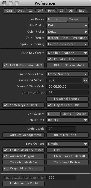
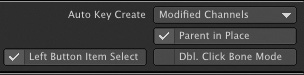
The Auto Key button at the bottom of the Layout interface is turned on by default. We discussed this briefly in Chapter 2, but the following is a hands-on tutorial to further explain when and why to use this feature. Auto Key does multiple things: It adjusts the values of existing keyframes automatically; it automatically creates keyframes where none are present; and it creates keys on all channels, or only on modified channels. For the Auto Key feature to automatically create keys, you need to make sure the Auto Key Create option is enabled in the General Options tab (press o). Set this to Modified Channels so that any commands, such as Move, Rotate, Size, or Stretch, are remembered for selected items at the current frame. Exercise 6.1 explains this feature further.
Exercise 6.1. Using the Auto Key Feature
For this exercise, you won’t even need to load a scene or any objects. The Auto Key feature in LightWave makes creating animations pretty easy. Almost everything in LightWave can be animated! For that reason, this quick project will have you animate the two default items in Layout, the camera and the light.
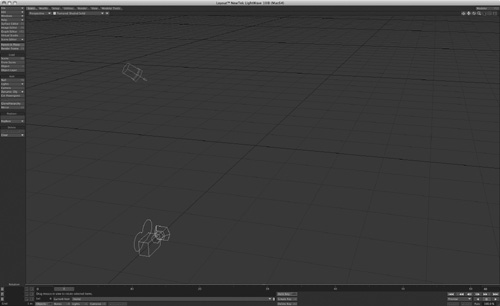
- Open LightWave, and if you’re already working on something, save it. Then from the File drop-down menu, select Clear Scene. You’ll see a Perspective view with the default camera and light visible, as in Figure 6.1 (on the next page).
Figure 6.1. A simple scene with two default items, a camera and a light, ready to be put in motion.
- Select the camera in one of two ways: by clicking directly on it, or by choosing the Cameras button at the bottom of the interface.
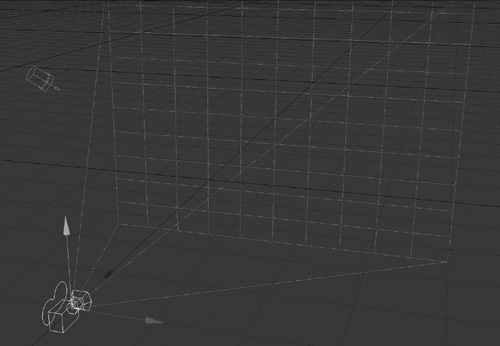
- When selected, the camera will be highlighted in yellow and you’ll see a dotted projection extend out from the camera, as shown in Figure 6.2. This area is what the camera sees.
Figure 6.2. When you select a camera, Layout highlights it in yellow and extends a dotted line from its “lens” to indicate its field of view.
Note
The virtual cameras shown in Layout scenes are merely representational. Their focal points are at their pivot points—where their positioning handles appear when they’re selected—not at their drawn “lenses.”
- Make sure your timeline is set to frame 0, which will be the start of your simple animation.
To understand how Auto Key works, you’ll compare creation of a simple camera animation with Auto Key on and off.
- If it’s activated, click the Auto Key button at the bottom center of the Layout interface to turn it off. (The button is white when Auto Key is on and blue when it’s off.)
- Press t to activate the Move tool. This tool is also found on the Modify tab.
Note
In the Layout window, you’ll notice that there is always a key at frame 0 by default. Thus, an object is locked in place even without Auto Key. Auto Key merely lets you make an adjustment at frame 0 (or any other existing keyframe) without having to re-create the key.
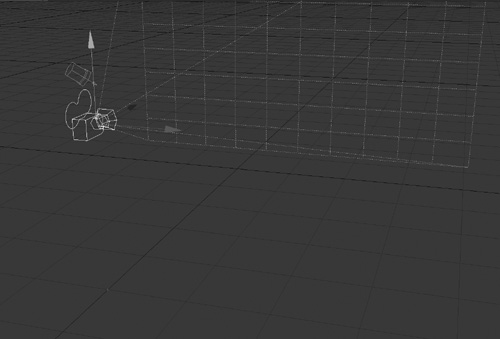
- With the Move tool active, click and drag the green handle that appears for the selected camera. Drag it up slightly from its current position, about 2 m or so, as shown in Figure 6.3.
Figure 6.3. Using the Move tool, drag the camera up a bit on the Y-axis.
- Click and drag the timeline slider forward to another frame.
The camera seems to jump back to its original position. Move the slider back to frame 0, and the camera returns to its original keyframed position. Unless you set a keyframe (or reset an existing one) after you change an object’s position, orientation, or other attributes, the adjustments aren’t captured and LightWave “forgets” them.
Note
If you can’t see the object to grab it, you can switch to the Back view by pressing the number 1 on the keyboard. Single-button-mouse Mac users, remember to use Control-click for right-mouse-button commands. Also, you can use your right mouse button (or equivalent) to quickly control up and down (Y-axis) movements.
- Click the Auto Key button to activate it (the button will turn white) and repeat steps 6 and 7.
- Drag the slider to frame 60, the last frame of your animation. (LightWave’s default length for new animations is 60 frames.)
This time, the camera stays where you put it. Auto Key automatically reset the keyframe in frame 0 to capture your camera move.
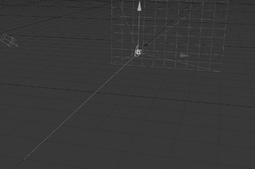
- With the timeline slider at frame 60, click and drag the blue handle for the camera and move it to the back of Layout, as shown in Figure 6.4. Auto Key automatically creates a new keyframe this time, capturing the new position information.
Figure 6.4. With the timeline slider at frame 60, the camera is moved to a new position.
So now your animation has two keyframes: one at frame 0, indicating the camera’s starting position, and another at frame 60, reflecting its end position. Let’s see how the camera gets from the first keyframed position to the other.
- Drag the timeline slider back and forth and you’ll see the camera move through the scene. LightWave automatically fills in (also commonly known as “in-betweening”) the motions needed to move objects between keyframes. Congratulations, you just made an animation!
This is a very basic example, but the principles are the same for even the most complex objects. Pick a point in time, position the item, and you’re building an animation.
- Now, press y to select the Rotate tool. At frame 60, click and drag the red ring to rotate the camera 180 degrees so that it’s facing in toward your current view (Figure 6.5).
Figure 6.5. With the timeline slider at frame 60, rotate the camera so it faces the scene.
- Click the Rewind button, at the bottom right of the interface, and then the Play button (the right-facing triangle). The camera will now move from frame 0 to frame 60, across the scene down the Z-axis, rotating as it goes.
To recap, at frame 0, Auto Key captured the camera’s position along the X, Y, and Z axes and its H, P, and B (Heading, Pitch, and Bank) rotation coordinates. At frame 60, the position and rotation changes you made were also recorded in a new keyframe, and LightWave interpolated the movements in between the two keyframes. Welcome to animation!
- To help you visualize movement within your project as you work in individual frames, LightWave can display a motion path that shows the route an object will take between keyframes. To see your camera’s motion path, press o to open the LightWave Preferences panel and check Show Motion Paths on its OpenGL tab.
- Drag the timeline to about frame 30, deactivate the Auto Key button at the bottom of the interface, and then move the camera to a new position.
- Once the camera is in a new position, click the Rewind button and then the Play button to see the animation. Notice a change? Of course not. With the Auto Key feature off, the position change for the camera was not recorded. You’ll also see that its motion path didn’t change.
- Slide the timeline back to frame 30. Turn Auto Key back on. Now move the camera again to a new position, and this time rotate it a little as well. Feel free to change the camera position on the Y-axis too.
- You’ll see that the motion path has now changed (Figure 6.6). Click the Rewind and Play buttons to watch the motion along the new path. Now the camera moves among three keyframes: 0, 30, and 60. Each keyframe stores object position and rotation information in time. The keyframes tell the camera to “be here” or “stay here” at a specific point in time.
Figure 6.6. When Auto Key is active and Show Motion Paths is turned on, manual adjustments to camera position are reflected in its motion path.

A word of caution about Auto Key: It can be quite helpful in setting up animations, but it can also be hazardous when you’re working on crowded scenes that require precise object placement. Accidentally nudge the wrong object with Auto Key on, and you can lose hours of painstaking adjustments. For those situations, you’ll want to become adept at manual keyframing.
Note
Using the Auto Key feature also requires that the Auto Key Create option be set to Modified Channels. You can find this by pressing o to open Layout’s Preferences panel, in the General tab.
Manual Keyframing
Auto Key appeals to our natural sense of the world. When you move something, it should stay where you put it. But there are times when Auto Key doesn’t provide enough control. In many ways, it’s like using a point-and-shoot camera. Everything is automatic and easy, but sometimes the automatic methods, which work more than 90 percent of the time, won’t let you do what you need to do. Just as a great photograph may demand manual camera control, LightWave setups with nuanced model motion and interaction require manual keyframing. Manual keyframing is vital to superb timing in your animations, and while you can’t develop that overnight, a few practice animations can get you started.
A good way to work is to turn off the Auto Key Create option in the General Options tab (press o) and work only with Auto Key enabled. While it’s not necessary to do, the Auto Key adjusts existing keyframes without the need to create them again after any changes are made. If there are no keyframes already created, either manually or with the Auto Key Create option previously enabled, LightWave will not create any keyframes automatically. If you accidentally move the timeline, you won’t create unwanted keyframes, destroying a precisely placed item.
So, here’s how you can think of it: If there are already keyframes for a Layout item, working with Auto Key on at the bottom of Layout will automatically record and keep any changes made to that item at that frame. If Auto Key Create is off in the Options panel, any changes you make to an item that does not yet have a keyframe will not be recorded.
Exercise 6.2. Manual Keyframing with Auto Key
Before you begin, there are a few things you should know: When there’s a blank scene and you load a single object into it, that object should automatically be selected. If you click to select the item and it’s not selecting, be sure you have Left Button Item Select turned on in the General tab of the Preferences panel (press o), as in Figure 6.7. If the control handles do not appear in the center of the object, make sure that the Show Handles option is turned on in the OpenGL tab within the Display Options tab (press d).
Figure 6.7. The Left Button Item Select feature is found on the General tab of the Preferences panel. Press o to open the panel.
By default, Layout assigns new scenes a duration of 60 frames, or 2 seconds. If your animation runs longer than that (most do), just increase the last frame number in the timeline. Be sure to add extra frames after your last keyframe, to give viewers time to register the actions that occur at that last keyframe. You can change the default animation length in the Preferences panel (press o) by changing the default frame number on the Defaults tab (listed as Def). You’ll need to quit and restart Layout to keep these settings.
Keyframing manually is more deliberate than using Auto Key alone. But what confuses many new animators is deciding when to use Auto Key and when to use manual keyframing in their animations. But you don’t have to worry about that! This exercise will instruct you on deliberately setting keyframes while still keeping the Auto Key feature active.
- A scene has been created for you to begin keyframing. Here, the cup will fall, bounce slightly, and land on the saucer. Load the scene by going to the File drop-down list and selecting File, then Load Scene. Choose the Cup_o_Tea_Static.lws scene from the book’s DVD in the CH6 folder of the 3D_Content directory. Alternatively, you can load a scene by clicking the Scene button under the Load category of the Items tab. Figure 6.8 shows the scene loaded into Layout.
Figure 6.8. A simple scene, ready to be put in motion.

- With the teacup scene loaded, be sure the frame slider at the bottom of the Layout interface is at 0, be sure Auto Key is enabled, and activate Auto Key Create on the General Options tab within the Preferences panel (press o) to have keyframes created automatically.
- Select Modified Channels from the selection area of the Auto Key Create command, as in Figure 6.9. In Modified Channels mode, new keyframes are created only for those channels that have been changed, whereas setting Auto Key Create to All Motion Channels creates a new keyframe for everything in your scene anytime you make a change to your selected item. This feature is not something you’ll use often, but at times you might need it. Suppose you’re creating an animation of characters dancing on a stage and each item’s motion channels (position and rotation) need to follow specific timing; creating keyframes with All Motion Channels enabled will save you time.
Figure 6.9. Be sure to set the Auto Key Create option to Modified Channels in the General Options tab.
It’s often convenient when animating to assemble all the objects or characters in a scene exactly as you want them to end up, then work backward to specify how they got there. Let’s do that with our teacup and saucer. We want them to be arranged as they are in the current scene at the end of our animation, so we’ll place the current scene in the final frame and then keyframe backward.
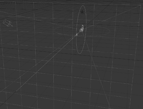
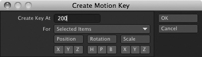
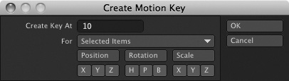
- Make sure you’re in a Shaded Solid view, from the top of Layout. Click the Objects button at the bottom of Layout, and then choose the CupAndSaucer: Cup listing from the Item drop-down list to select the teacup object. It will be highlighted with a yellow bounding box—that is, a wireframe box will appear as a representation of the object’s 3D space. This animation is 200 frames long, so create a keyframe for the teacup at frame 200, the last frame. Since it’s already in its “final” position, you can simply lock it in place now. Click the Create Key button beneath the timeline. It will have a 0 for the Create Key At entry because your timeline is at frame 0. Enter 200 in the requester, and make sure that Selected Items is chosen and that all of the channels are clicked, as in Figure 6.10.
Figure 6.10. Create a keyframe at 200 for the cup.
- Click OK to close the Create Motion Key panel. With the timeline at 0, and with the cup selected, press t to select the Move tool (or click the Move tool on the Modify tab). Move the cup up in the scene, about 1.5 m, by clicking and dragging its green (Y-axis) handle, or use your right mouse and drag for Y-axis movement. You can see the amount of movement in the numeric display at the lower-left corner of Layout (Figure 6.11).
Figure 6.11. Move the teacup up and away from the saucer.

- Now you should see a small white line tracing from the saucer to the cup. This is a motion path. Because you created a keyframe at frame 200, and you haven’t moved the cup at frame 0, and Auto Key with Auto Key Create is on, LightWave has created a keyframe for you automatically at frame 0, in the cup’s new position. If you were to drag the timeline or click the Play button at the bottom right of the interface, the cup would slowly fall down into its original position.
- Click and drag the timeline slider forward to frame 200. The cup should be resting on the saucer at this point, in its original position. This is also where you want the cup to land when it first falls down. You can copy the current keyframe value by clicking the Create Key button (or pressing Enter) and then enter 10 in the Create Key At field (it will read 200 because this is the current frame your timeline slider is on). After you enter 10, click OK. You’ve now copied a keyframe. Figure 6.12 shows the keyframe.
Figure 6.12. Make a keyframe at frame 10, with the cup in the same position as in frame 200.
Note
If you don’t see a motion path, you need to make it visible. Press o to open the Preferences panel and check Show Motion Paths on its OpenGL tab.
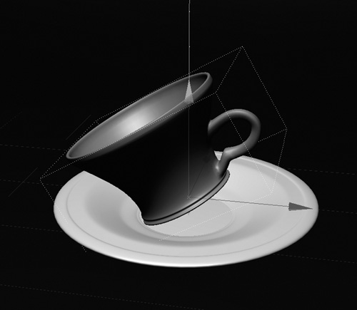
- With the teacup still selected, make sure your timeline is on frame 10. Then, press y to activate the Rotate tool (also on the Modify tab). When the tool is active, you’ll see rings around the selected object. Click and drag the blue ring to rotate the cup on the Bank channel about 30 degrees. You’ll see the degree of the rotation in the lower-left corner of the interface. Then move the cup up slightly so it’s not going through the saucer. Figure 6.13 shows the example.
Figure 6.13. Using the Rotate and Move tools, rotate the cup at frame 10 on its Bank channel.
Note
A quick way to jump to any frame in Layout is to press f to call up the Go To Frame command. When it appears, just enter the desired frame number and press Enter (or Return on a Mac). Note that you do not need to highlight and delete the value in the Go To Frame requester. The old value will be highlighted when the requester appears, so you can just type the new frame number to replace it.
- Drag the timeline slider to frame 20. Now use the Move tool by selecting it from the Modify tab (or by pressing t), move the object up a bit, and give it different rotation. Remember that you can press y to jump to the Rotate tool. Figure 6.14 shows the change.
Figure 6.14. Using the Move and Rotate tools, reposition the cup at frame 20.

Note
Because the Move and Rotate commands are used so often, Layout provides many ways to get to them. In addition to clicking their tool buttons on the Modify tab or pressing t for Move and y for rotate, you can press the spacebar to cycle through the Move, Rotate, Size, and Stretch tools. Additionally, if your computer mouse has a scroll wheel, you can use it to toggle between Move, Rotate, and Stretch.
- Click the Rewind button, at the bottom right of the interface, just above the Preview menu. Then click the Play button, which is the right-facing arrow, also at the bottom right of the interface.
When you play the animation, you’ll see your cup fall and quickly bounce. It’s sort of OK, but it drifts through the saucer. What’s up with that? Didn’t you keyframe it at frame 10 to land on the saucer? You did, but because LightWave’s motions are actually spline curves, there’s a fluidity between keyframes. This interpolation is your friend in most animations, but often you need to control it. We’ll set up a few more keyframes first, to finish the animation, and then you’ll see how to control the “drifting” you see before and after set keyframes.
- Press f to call up the Go To Frame command. Enter 200 to jump to the cup’s final resting position, and then copy its keyframe information to frame 30, using the method described in step 7.
Click the Play button. You should see the teacup move and rotate between keyframes 0 and 30. You can shuttle through the animation by grabbing the timeline slider and dragging.
Pretty good start, but there are still a few problems with the motion, right? The cup doesn’t really bounce or land realistically; it sort of floats and drifts a bit before it comes to a rest. Because LightWave creates motion curves between keyframes, you need to control the curves for each keyframe. You can do this with the Graph Editor. However, there is a quicker way to change this motion right in Layout. We’ll use that option first and then use the Graph Editor, so you can see both methods.
Note
You don’t need to move the timeline slider to set keyframes throughout an animation if you’re manually setting keyframes. However, moving it helps keep you organized and aware of the current animation frame.
Before you tweak the teacup animation further, note that you can delete keyframes as easily as you create them. Press the Delete Key with the frame slider on a keyframe, and the Delete Motion Key dialog will open, with the current frame already selected (Figure 6.15).
Figure 6.15. Deleting keyframes works the same as creating them. Select an item to adjust, go to a specific point in time, and click the Delete Key button at the bottom of Layout.

As with creating keyframes, the timeline slider does not need to be on the specific keyframe to delete a key. Enter the number of the key you want to delete when the Delete Motion Key dialog opens. Again, use your numeric keypad to save time! And remember, just as you can create keyframes for specific channels, you can delete them as well.
The tutorials in this motion chapter are really basic, and probably the simplest things to do in this book, but it’s important for you to get the hang of keyframing. You told the cup to be at a certain position at frame 0, the beginning of the animation. Then you moved the object to its resting position at the end of the animation at frame 200. Then you told LightWave to copy that position of the cup at frame 10, and again at frame 30. You also changed its position and rotation at frame 20. It will then sit there until frame 200, unless you make another keyframe change. LightWave interpolates the frames between 0 and 200, even if there is no movement from 30 to 200. Sort of like magic, you made an animation. Automagically, the motion curve that the computer created is the in-betweening that traditional animators would have to draw by hand. (Automagically is a technical term.)
Control Curves with the Move TCB Tool
Now you’ll move on to correcting the “drift” in the teacup animation. You’ll start by using Layout’s Move TCB tool, and later in this chapter you’ll explore an alternate approach that uses the Graph Editor. The Move TCB tool, found on Layout’s Modify tab, is perfect for quickly controlling the motion curve created from multiple keyframes.
Exercise 6.3. Working with the Move TCB Tool
- If you don’t have your teacup scene still in Layout with the multiple keyframes you created, load the Cup_o_Tea_Motion.lws scene from this book’s DVD.
Click the Play button again to review the animation. The teacup droops down too low, into the saucer object, on frame 10. Due to the motion curve, the teacup slides between the curves. Not desirable, but fixable.
- Press f to call up the Go To Frame window and type 0 (zero), or drag the slider to the beginning of the timeline.
- On the Modify tab, select the Move TCB tool, shown in Figure 6.16. Alternatively, you can press Control+G to activate the tool.
Figure 6.16. The Move TCB tool, which can be found on the Modify tab in Layout.

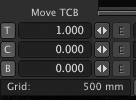
- Note the info area on the bottom left of the Layout screen. You’ll see that this area now lists values for T, C, and B—shorthand for Tension, Continuity, and Bias. Clicking and dragging in the current frame will increase or decrease the tension for the current frame, which is 0.
- Click and drag to the right until the tension reads 1.0, as in Figure 6.17.
Figure 6.17. A Tension value of 1, as reflected in the Move TCB tool’s info area.
- Go to frame 10 and this time, set a tension of –1.0 by clicking in the Layout window and dragging to the left.
- Now set a 1.0 tension for frames 30 and 200. This will help control the motion at these keyframes. Leave frame 20 alone. You want the cup to come up to this keyframe and drop back down. Setting a tension value here would make it pause in mid-air.
Play back the animation, and you’ll see that the teacup starts out slower and hits the saucer with more force. It bounces up at frame 20, comes to rest at frame 30, and then holds firm through frame 200. The ease in and ease out at frames 0 and 30, respectively, are set with a positive tension value. The negative tension value helps to force the motion for the teacup at frame 10. But notice that frame 10 still slopes down into the saucer. While the motion of the fall and bounce are better, the motion still needs a bit of adjustment. The reason is that settings for each keyframe in a motion curve affect all the other keyframes. You set keyframes before and after frame 10, and the motion settings before and after the frame affect frame 10’s settings. Fortunately, this is easy to adjust.
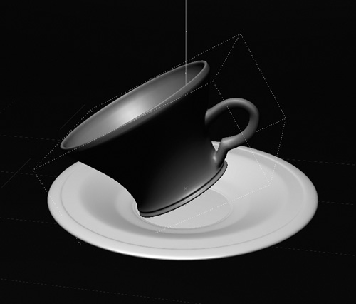
- Go to frame 10, and select the teacup. Simply move it up on the Y-axis enough so that it rests on the saucer, as in Figure 6.18.
Figure 6.18. A slight keyframe adjustment fixes the motion curve.
You can add frames to a resting position by simply creating another keyframe. For example, if you wanted the teacup to stay in place only until frame 150, you would create an additional keyframe in the same position. Just think about your timeline process and what you’re trying to accomplish. Be specific in what you want your object to do, and you’ll have an easier time creating motions.
There are a few things you need to know about TCB and how to set the values:
• T, C, and B values can range from –1.0 to 1.0.
• Tension is used to ease in or ease out of a keyframe. You would set a tension of –1.0 to make an item slow down as it reaches its keyframed position. On the flipside, you’d use a tension of 1.0 to make an object speed up as it reaches its specified position—perhaps for things like a ball bouncing. As you’ve seen, to set tension using the Move TCB tool, just click and drag in an item’s desired keyframe.
• Continuity is used to smooth or punctuate changes in motion. A positive continuity setting tells an object to “glide” smoothly as it passes through a keyframe. A negative continuity setting briefly “freezes” an item in its keyframed position before its motion continues, and is useful for exaggerated or robotic character movements. To set continuity using the Move TCB tool, hold the Control key and click and drag in an item’s desired keyframe.
• Bias is used for setting up anticipation. You can set a positive bias to create slack after a keyframe. Let’s say your fire truck is speeding around a corner. Add bias to that keyframe, and it will slide around that corner. A negative bias creates slack before a keyframe. You could use this for, say, a racecar before it goes into a sharp turn. To set bias using the Move TCB tool, right-click and drag with the right mouse button in Layout for an item’s desired keyframe to change Bias.
Keyframe Rules for Thought
There are a few more things you should know about keyframing in LightWave 10. A common misunderstanding with keyframes is that the more of them you have, the more control you will have in a scene. Not so! When you create keyframes in LightWave, you’re creating curves. If you’ve worked in an illustration program like Adobe Illustrator, you’ll know that you can build a smooth curve with as few as three points. But if you were to add more points—or, in this case, more keyframes—it would be that much harder to control timing and fluidity in your motions.
A good rule of thumb to use when setting keyframes is to start by setting your object’s first and last keyframes, and then set any that fall in between. For example, say you want an object to move down a path and around an obstacle. The movement needs to be smooth, and trying to guess the timing might be tough to do. Set the beginning keyframe and then the ending keyframe to create the initial motion path. If you drag the timeline slider, the object moves between the two keyframes. If you move the timeline slider to the point where the object would move around the obstacle, you’ll have the exact frame to set your next key. By creating the keyframe at this point, you’ve adjusted the motion path evenly.
In later chapters, you’ll have many more opportunities to work with advanced keyframe techniques.
Navigating the Graph Editor
You’ve now worked through a series of basic keyframing steps. The process of creating keyframes for our simple exercise is the same as the one used for large-scale animation projects. The only difference is that big projects have a lot more keyframes. Overall, the increase in complexity results from the fact that there simply are more items to control in larger scenes. To help manage scenes that contain multiple keyframes, LightWave provides the Graph Editor.
You can access the Graph Editor by clicking the Graph Editor button at the top left of the screen in any Layout tab, or you can press Control+F2 to call up the panel (Figure 6.19).
Figure 6.19. Opening the Graph Editor from the top left of the Layout interface gives you specific controls over your item’s motions.
When you open the Graph Editor, you’ll notice four general areas:
• The Curve Bin is the upper-left quadrant (Figure 6.20) of the panel (you won’t see the name “Curve Bin”). This is the area of the Graph Editor where you place and select the specific channels (the curves) you want to edit.
Figure 6.20. The Curve Bin zone of the Graph Editor is the area where you put channels you want to edit.
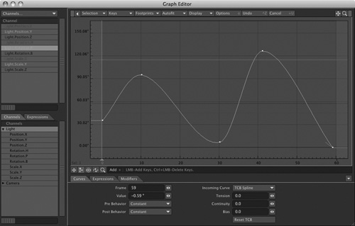
• The Curve Window zone is in the largest area, the upper-right quadrant (Figure 6.21). This is the area where you edit curves. Here, you can adjust attribute values, edit keyframes, and more.
Figure 6.21. The Curve Window is the large main area of the Graph Editor, where all curve editing takes place.
• The Curve Controls zone is in the lower-right quadrant (Figure 6.22). Here you can set frames, values, behaviors for keys, and modifiers, apply expression plug-ins and spline controls, and so on.
Figure 6.22. The Curve Controls zone, in the lower-right quadrant of the Graph Editor, is where you set specific controls, such as expressions, modifiers, spline controls, and more.
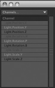
• The Scene zone is in the lower-left quadrant and shows the elements of your current scene (Figure 6.23). Lights, cameras, and objects are listed here, and you can select any or all of their channels and drag them into the Curve Bin to begin editing. This area also shows you any expressions that might be applied.
Figure 6.23. The Scene zone, in the lower-left corner of the Graph Editor, shows a list of items in your currently loaded scene.
You will work with each zone to adjust, modify, or create various motions, timing, and values for LightWave elements. Here you can control all Layout items, from the camera to lights to objects—including color, light intensities, morph envelopes, and more. You may be asking yourself where you should begin with the Graph Editor and wondering what it really does. Good questions! The Graph Editor is a complex part of Layout, one that is best explained through examples.
The exercise in the following section illustrates how to navigate through the Graph Editor interface.
Working with Channels
When you begin creating an animation, you will often need specific control over one keyframe or a group of keyframes. The Graph Editor gives you this control, but you first must understand how to set up the channels with which you want to work. This exercise introduces you to working with the Position and Rotation channels for a light and a camera.
Exercise 6.4. The Position and Rotation Channels
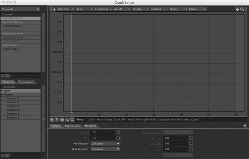
- In Layout, save any work you’ve been doing and select Clear Scene from the File drop-down menu. Then, select the default camera.
- Click the Graph Editor button on the toolbar (or press Control+F2) to enter the Graph Editor.
You don’t need to load anything into Layout as you follow along here.
Look at Figure 6.24, and you’ll see that the attributes in the Scene list (lower-left quadrant) relate to the items in Layout, such as the camera. In the upper-left quadrant, you’ll see all of the camera’s channels already loaded. If you’ve got an item selected when you open Graph Editor, all that item’s channels will automatically load into the panel. Click the small white triangle next to the Camera entry in the Channels tab to expand and display all the appropriate motion channels for the camera.
Figure 6.24. The Scene list in the lower left of the Graph Editor shows the items in your scene. Clicking the small white triangle next to an item expands it to show all its channels. The selected camera in Layout has all of its motion channels loaded in the Curve Bin.
- Double-click the Light label in the Scene list area, just above the Camera listing. This is in the lower-left corner of the Graph Editor interface.
Double-clicking the Camera item adds all its channels to the Curve Bin, overriding any channels already in the bin. Doing this now makes those channels available for editing. If you were to hold the Shift key while double-clicking, you’d add to the current list of channels in the Curve Bin.
You can also just click and drag a specific motion channel from the Scene list to the Curve Bin. This is great if you just want to add a selected channel or two. If you hold the Shift key, select a channel, and then select another channel, all channels in between will be selected. You can then drag those channels to the Curve Bin. And, as in many areas within LightWave, such as the Surface Editor, holding the Control key while selecting enables you to select noncontiguous channels.
Note
You can maximize the Graph Editor window by clicking the standard system maximize button next to the X in the top corner of the panel window. You can also reorder items in the Curve Bin by clicking and dragging them. Neither action affects your scene.
- Go back to the Scene list area at the bottom left of the Graph Editor and expand the Camera item’s channels, if you haven’t already, by clicking the small white arrow to the left of the Camera label. Figure 6.25 shows the expansion.
Figure 6.25. When you expand an item’s channels, you can use the scrollbar on the right of the Scene Display quadrant to access them; you can also resize the display area.
- Double-click any of the Camera’s channels in the lower-left zone.
The channel is now added to the Curve Bin and replaces any other channels stored there. (You can add more channels to the Curve Bin without replacing the active channels by holding Shift when you double-click a channel.)
Note
You can resize the individual quadrants in the Graph Editor by placing your mouse cursor on the borders between areas and then clicking and dragging them.
- To add the Position.X and Rotation.H channels to the Curve Bin, hold down the Control key and click their name listings. Then drag them up to the Curve Bin. This is another way of adding channels without replacing them.
Now that you know how channels are added to the Curve Bin, you can modify or edit them in many different ways.
Note
If you have noncontiguous channels (channels not in order) to select, use the Control key rather than the Shift key to make your selections in the Scene list.
Working with the Graph Editor
Editing curves is one of the primary functions of the Graph Editor. To help understand the flow of editing curves, think of your workflow as progressing from bottom left, to top left, to top right, to bottom right.
Editing Curves
Layout generates editable curves anytime you specify a change in a setting’s value over time, a change to control object position and rotation, or a change to any animatable property of a light, object, camera, or surface. No matter what the property or attribute is, you work your way through the Graph Editor the same way, and the Curve Window is where you control its curves.
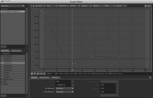
Figure 6.26 shows the Graph Editor in full frame with the same teacup scene from earlier in this chapter loaded (Cup_o_Tea_Animated.lws). Use your own version of the scene, or load it from the book’s DVD.
Figure 6.26. With a scene loaded into Layout and the tea cup object selected, opening the Graph Editor reveals all motion channels already in place in the Curve Bin for the selected teacup object.
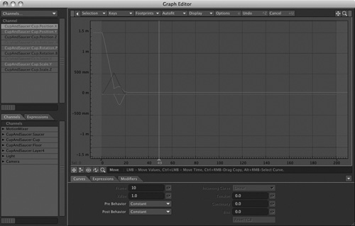
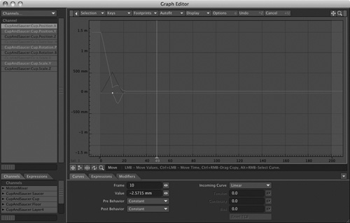
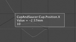
In Figure 6.26, the first channel (Position.X) in the Curve Bin is selected by default. In the Curve Window, the channel that represents the object’s X position is highlighted. On your computer, you’ll notice that each position channel has a specific color in the Curve Bin: X is red, Y is green, and Z is blue. You can change these default colors in the Preferences panel. The same color represents the corresponding curve in the main Curve Window. If you move the mouse pointer over one of the small colored dots (which represent keyframes) on an active curve (in this case, the item’s motion path), numeric information appears (Figure 6.27).
Figure 6.27. Moving the mouse pointer over a keyframe instantly displays the keyframe number, the value, and which channel (such as Position.X) you’re working with.
If you like, and have the screen real estate, feel free to resize the Layout window and the Graph Editor to keep both panels fully visible all the time. To resize the Graph Editor, you can do the following:
- Drag the lower-right corner of the Graph Editor window. Make sure that the window is not maximized.
- Click and drag the Layout window from the top of the panel, and move it to the upper-left portion of your screen.
- Open the Graph Editor and resize it as well. Move it beneath the Layout window.
Additionally, you can keep the Surface Editor and Preset Shelf (found under the Window drop-down) open while you’re working in Layout if you like, perhaps also using the Dope Track. This is beneficial because you can make a change, see the result in Layout, and continue working. You do not have to continually open and close panels—simply leave them open. Either a large monitor or a dual-monitor setup is helpful for screen real estate when setting up configurations like this.
Adjusting Timing in the Graph Editor
The Graph Editor enables you to do many things, such as create, delete, or adjust keyframes for specific channels. You can also modify various entities within LightWave, such as surface color and light intensities. One of the more common uses for the Graph Editor is adjusting the timing of elements in your LightWave scenes. The Graph Editor has many uses, which you will inevitably take advantage of at some time during your career as an animator.
Exercise 6.5. Working with the Graph Editor
- Load the Train scene into Layout from the 3D Content directory on this book’s DVD.
This loads a simple scene with the train pulling into frame, stopping, backing up, and turning. It has a rotation and position change throughout the animation.
- The Train object should already be chosen because the scene was saved with it selected. Open the Graph Editor.
You’ll see that all the object’s channels are automatically loaded into the Curve Bin. However, in this tutorial, you’re adjusting only the object’s timing on the Z-axis; therefore, the remaining channels are not needed. For safety, so you don’t accidentally change a curve you don’t want to, isolate the specific curve to edit in the Curve Bin.
Note
As you work through scenes with the Graph Editor open, the channels will not automatically update in the Curve Bin. You can choose Get Layout Selected from the Selection drop-down (Shift+G) to update the Graph Editor.
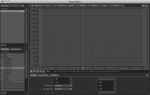
- In the Scene window, expand the Train:Engine listing and double-click the Rotation.H channel. All existing channels in the Curve Bin will be replaced by the Rotation.H channel (Figure 6.28).
Figure 6.28. Double-clicking the Rotation.H channel in the Scene Bin adds the motion channel to the Curve Bin.
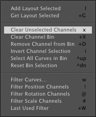
The Rotation.H channel already existed in the Curve Bin before you double-clicked to add it by itself. You can, however, select all of the channels you’re not interested in using and remove them. You can right-click the selections and choose Remove from Bin (Figure 6.29). You also can choose Remove Channel from Bin (Figure 6.30) or Clear Unselected Channels (Figure 6.31) from the Selection drop-down at the top of the Graph Editor panel.
Figure 6.29. To remove selected channels, you can right-click the selections and choose Remove from Bin.
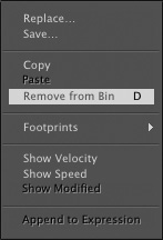
Figure 6.30. Choosing Remove Channel from Bin from the Selection drop-down list removes selected channels from the Curve Bin.

Figure 6.31. The Selection drop-down list at the top of the Graph Editor gives you access to a number of controls, including the ability to clear unselected channels from the Curve Bin.
Note
If you take a close look at the functions available in the Selection drop-down, you’ll see that you can do much more than simply remove channels. You can clear the Channel Bin, reverse selections, select all curves, and more. Experiment with these options to get a feel for their uses.
You don’t have to remove channels you don’t plan to edit from the Channel Bin, but clearing channels you don’t need helps keep the Channel Bin uncluttered and organized. It also prevents you from accidentally editing the wrong curve.
- Back in the Curve Bin, select the single Rotation.H channel (if it’s not already selected, since it’s the only channel there). You’ll see it highlighted in the Curve Window.
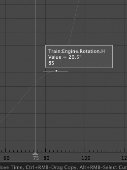
This represents the motion of the H (Heading) channel for the object. The tall vertical line is the current frame.
- Move your mouse over the first small dot (the first keyframe) on the curve for Rotation.H to see the information for that keyframe (Figure 6.32).
Figure 6.32. Move your mouse pointer over the first dot, which represents the first keyframe for the Pitch (P) rotation motion channel.
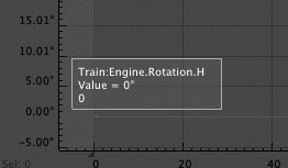
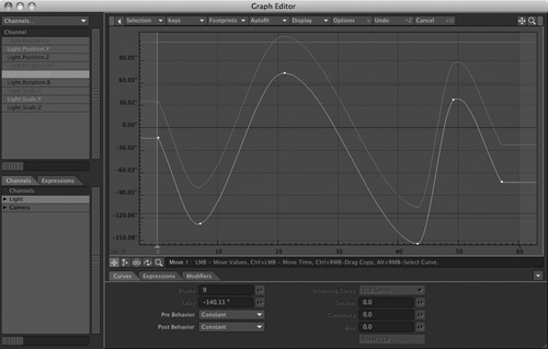
The information tells you what curve it is; in this case, it is Rotation.H for the Train:Engine object. It also tells you the frame number of the keyframe and the value of the relevant setting at that frame. In this case, the setting value is the object’s rotation at frame 0, which reads –0 degrees. This means the object is not rotated at frame 0. As the object rotates in successive frames, its rotation value is reflected in the Curve Window.
It can be hard to identify that first keyframe in the curve. To simplify this, you can use the Graph Editor’s Custom Point Color function.
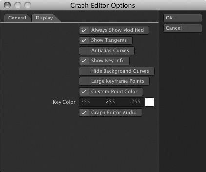
- While still in the Graph Editor, press d to call up the Graph Editor Options panel with its Display tab open. Click Custom Point Color at the bottom of the list, and the color selector will become active, as in Figure 6.33. The default color, white, is fine, so simply click OK to close the panel. Your keyframes in the Curve Window will now be easier to identify.
Figure 6.33. Setting the Custom Point Color option in the Graph Editor Options panel helps make a curve’s keyframes more visible.
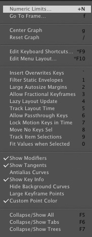
A number of other commands within the Graph Editor Options panel can help you when working with the Graph Editor. You can also access these commands and others easily by clicking the Display drop-down list from the top of the Graph Editor interface. Figure 6.34 shows the list of commands for Display.
Figure 6.34. The Display drop-down list at the top of the Graph Editor interface gives you controls for working in the Graph Editor Options panel.
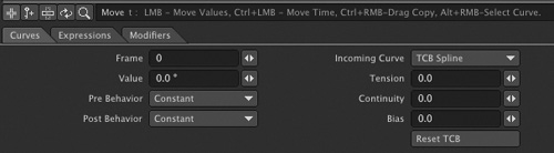
- In the Curve Window, click the first keyframe to select it. Be sure that the Move edit mode button is selected. It is the first button located above the Curves tab, beneath the Curve Window, as shown in Figure 6.35. You can directly click the key to select it, or use the right mouse button to draw a region of selection. This second method is good for selecting multiple keyframes.
Figure 6.35. The Move edit button in the Graph Editor resides just below the Curve Window, along with Add, Stretch, Roll, and Zoom. Selecting a specific tool displays the appropriate keyboard legend. Here, the Move tool is selected, enabling you to move selected keyframes in the Curve Window.

With Custom Point Color active, you’ll see the keyframe highlight slightly, and the values throughout the Curves tab will appear at the bottom of the screen, as shown in Figure 6.36.
Figure 6.36. When a keyframe is selected, the commands in the Curves tab area become available. Here, a right-click and drag lasso-selects the key.
Note
Beware of clicking around too quickly in LightWave. It happens to the best of us! Doing so in the Graph Editor can really screw up your keyframes, because it’s easy to click-select a keyframe and then accidentally click-drag slightly to change its value. Instead of clicking in the window to make a selection, right-click to make a lasso selection. Not only will you be sure you’re getting the correct keyframe (they are pretty tiny), you also won’t accidentally change it, because the lasso tool can’t change settings values.
The middle of the Graph Editor interface offers five small tool icons for you to choose from: Move, Add, Stretch, Roll, and Zoom. When you select one, information is displayed to its right, explaining its function and keyboard shortcut.
You can use the Move tool to select and move single or multiple keyframes in the Curve Window.
- Select the key at frame 75. Next, choose the Move tool and click and drag the keyframe in the Curve Window.
Notice that you can move only its value (up and down). Doing this changes the position of the object in Layout.
- Move the keyframe up to set the value around 20 degrees.
Let’s say you do not want the Train:Engine object to rotate until frame 85, rather than starting its motion right at frame 75. This kind of delayed movement is easy to do in the Graph Editor.
- Make sure that the Move tool is selected. While holding down the Control key, click and move the 75 keyframe to the right. You’ll see the frame number appear over the keyframe (Figure 6.37).
Figure 6.37. Holding the Control key and moving selected keyframes adjusts timing. You didn’t realize it was this easy, did you?
Note
If you don’t care to hold down the Control key and use the mouse, you can type in a keyframe number instead. At the bottom of the screen in the Curves tab, you can enter the selected keyframe by clicking in the Frame field and typing its frame number. You also can set values by typing in the Value field.
- Adjust the value and keyframes of selected objects and return to Layout to see the effects. You can adjust values by dragging the keyframes in the Curve Window or by entering them numerically in the Curves tab area.
Additionally, you have a number of key controls available from the Keys drop-down list at the top of the Graph Editor panel. Figure 6.38 shows the Numeric Move selection, which enables you to numerically set offset values. Soon you’ll get the hang of editing in the Graph Editor.
Figure 6.38. The Numeric Move selection enables you to set a specific numeric value to move a key.

Take a look at your animation. Click the Play button to see how the values you’ve edited in the Graph Editor have changed the object’s motion. Feel free to play around with various movements of keys from different channels in the Graph Editor to see the results.
There’s much more to the Graph Editor than this. One really good option to try out is Lock Selected Keys, from the Keys menu. This is really handy if you don’t want to accidentally move a perfectly set keyframe. The first part of this chapter guided you through basic navigation and editing of channels and keyframes. Next, you’ll learn about moving groups of keyframes, adjusting their curves, and adding modifiers to them.
Copy Time Slice
Going beyond basic keyframing, you can control your animations with the Copy Time Slice command. Let’s say you’d like to copy an object’s position at a point where there is no keyframe. What do you do? You could do it manually, by writing down the Move and Rotation values for that frame and entering them in a new keyframe. A much easier way, though, is to use Copy Time Slice in the Graph Editor.
Exercise 6.6. Using the Copy Time Slice Feature
- Select the curve you want to edit, such as the Position.Z channel, using the files from Exercise 6.5. You can double-click this channel in the Scene Bin to quickly add it to the Curve Bin. Drag the timeline bar to the desired frame of motion, such as frame 45 (in the main Curve Window), as shown in Figure 6.39. To drag the timeline slider, grab it from the bottom.
Figure 6.39. Use the timeline slider in the Graph Editor to move through your item’s motion.
- From the Keys drop-down list, select Copy Time Slice (Figure 6.40).
Figure 6.40. The Copy Time Slice command, accessed from the Keys drop-down list, captures the channel values for whichever frame is selected with the timeline slider.

- Drag the timeline slider to frame 140, where there is no keyframe.
- From the Keys drop-down list, select Paste Time Slice. A new keyframe is created with the values from the previous position.
Note
You can also use the keyboard shortcuts for Copy Time Slice: Control+C for copy, and Control+V for paste. This is the same for Macintosh and Windows systems.
Copy Time Slice is an extremely handy function of the Graph Editor. If you set two keyframes in Layout for an item—at frames 0 and 90, for example—LightWave will interpret the motion for the frames in between those two keys. Earlier you read about “in-betweening.” Using Copy Time Slice enables you to copy the settings LightWave has calculated for any interpolated frame and copy them to any other frame or keyframe on that curve.
Multicurve Editing
But wait! There’s more! You can also use multicurve editing when you want to edit multiple curves simultaneously or use curves of different items as references. By selecting the desired curves in the Curve Bin (as demonstrated earlier in this chapter), you can edit them together as one in the Curve Window. You easily can drag and drop curves from the Scene Display window (in the lower-left zone of the Graph Editor) into the Curve Bin. For example, you might combine the Position.X of an object with the Rotation.Y of a light, and add in the Scale.Z of a camera. You can use any channel you want.
Foreground and Background Curves
When you add selected curves to the Curve Bin, you can see them in the Curve Window and view them as either foreground or background curves. Curves that are selected in the Curve Bin will become editable foreground curves in the Curve Window; curves that are not selected will be non-editable background curves.
Note
Here’s a really quick way to instantly select all curves in the Curve Bin. Hold the Control key and press the up arrow key. Deselect all by holding the Control key and pressing the down arrow key.
Working with foreground and background curves has its benefits. You can interactively cut and paste keyframes from one curve to another. You can also replace an entire curve with another, or lock areas of curves together. By having multiple curves selected when you create keys, the curves can be identical at those selected areas during an animation. Additionally, you have the ability to compare one curve to another, such as a light intensity to the H rotation of a camera. If you remember how Chapter 1, “LightWave Modeler,” talked about using layers both for reference and as a tool, the same can be said for foreground and background curves in the Graph Editor. This next exercise demonstrates some of these features.
Exercise 6.7. Working with Foreground and Background Curves
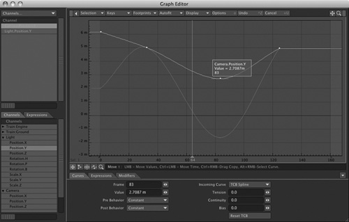
- Clear Layout (you can press Shift+N) and open the Graph Editor. You might need to click into the Layout window to activate the Shift+N command to Clear Scene. If the Graph Editor was already open, it will automatically be cleared with the Clear Scene command.
- Move Camera Position.X and Light Position.Y to the Curve Bin. Do this by expanding the item in the Scene Display (bottom left) and then dragging the desired motion channel up into the Curve Bin.
- When loaded, hold down the Shift key and select both channels in the Curve Bin.
You’ll see both curves highlighted in the Curve Window. Right now there are only straight lines because the channels have no motions applied.
- Select the Add Keys button beneath the Curve Window (Figure 6.41).
Figure 6.41. You can choose to add a key from the Graph Editor window, and you can also use the Move, Stretch, Roll, and Zoom commands.
- Click once in the top area of the Curve Window and once near the bottom right, similar to Figure 6.42. You’ll see the two curves adjust to the keys you just created.
Figure 6.42. You can create keyframes for the selected motion channels directly in the Curve Window.
Note
Remember that you can click and drag on the bar between the Curve Bin and the Scene Display windows in the Graph Editor to quickly resize the two windows.
Note
At times, your curve may be out of view in the Curve Window. As in Modeler and certain views in Layout, just press a to “fit all.”
Navigating the Curve Window
When you select multiple curves, you can edit them together, create keyframes together, and so on. However, you also can adjust one of these curves based on the background curve: Simply select only the curve you want to adjust in the Curve Bin. The remaining curves in the Curve Bin appear slightly darkened in the background of the Curve Window. From there, you can select the Move tool and click and drag a keyframe to change its value. Here are a few quick steps to remember when working in the Graph Editor:
• Select the Move keyframe button (in the center of the Graph Editor) and click and drag to adjust the selected key(s).
• Select the Move keyframe button and click and hold the Control key to adjust the selected key’s position in time—for example, to move a keyframe from frame 5 to frame 15.
• Hold the Alt key and click in the Curve Window to adjust the entire Curve Window view.
• Press . (period) to zoom in on the Curve Window; press , (comma) to zoom out.
• Press a to fit all contents of the Curve Window into view. For example, after you’re done working in a zoomed view of the Curve Window, press a to instantly fit all editable keyframes into the window.
• Press Shift+G to import curves into the Graph Editor. There’s no need to close the Graph Editor, select your next item in Layout, and then reopen the Graph Editor to add a particular curve. Instead, just move the Graph Editor aside, select an item in Layout, return to the Graph Editor, and press Shift+G to update with the new selection.
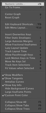
• Choose Numeric Limits from the Display drop-down list at the top of the Graph Editor window (or press Shift+N) to set minimum and maximum frames for the Curve Window (Figure 6.43).
Figure 6.43. Use Numeric Limits to control the frame and value settings in the Curve Window.
• Holding Control+Alt while moving the mouse left and right, or up and down, drags and zooms the Curve Window. You also can set a minimum and maximum value. Alt-drag options are similar to those used in Layout’s Perspective viewport.
Exploring Additional Commands in the Graph Editor
In addition to the commands you’ll use most often as you animate your scenes, you should know about the Graph Editor commands that can help you increase the speed of your workflow. As you’ve learned in other areas of LightWave, right-clicking in certain areas gives you access to additional tools that enable more control. The same goes for the Graph Editor.
Footprints
A handy feature of the Graph Editor is its ability to create footprints for a selected channel. To help you keep track of your adjustments to a keyframe or curve, a footprint cues you visually to remind you how the item looked before you began adjusting it. A footprint also lets you retrace your steps, or backtrack, if you choose to undo an adjustment. Follow this next tutorial to learn more about footprints.
Exercise 6.8. Creating Footprints
- Open Layout, clear the scene, and open the Graph Editor.
- Select the light in the Scene window of the Graph Editor and drag it to the Curve Bin.
All the motion channels for the light are added to the bin, as shown in Figure 6.44.
Figure 6.44. Selecting just the light from the Scene Display area and dragging it to the Curve Bin adds all its motion channels.
- Select the light Rotation.P, which is the Pitch rotation for the light. Of course, any selected channel will do for this exercise.
When a channel is selected, you’ll see it highlighted in the Curve Window.
- Select the Add Keys command (the second small icon beneath the Curve Window), and then click throughout the Curve Window to create some keyframes for the selected channel. Figure 6.45 shows the channel with a few keys added.
Figure 6.45. A few keyframes are added to the light’s Rotation.P channel in the Curve Window.
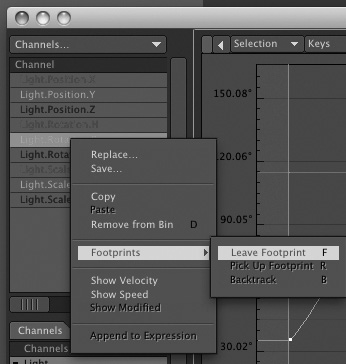
- Go back to the Curve Bin, and with the Rotation.P channel still selected, right-click it to open the pop-up menu.
- Choose the Footprints selection and then select Leave Footprints. You also can do this through the Footprints drop-down list at the top of the Graph Editor, as shown in Figure 6.46.
Figure 6.46. Right-click a selected channel to select the Footprints option, or select the Footprints drop-down list at the top of the Graph Editor.
It won’t look like much has happened in the Curve Window, but wait.
- Right-click and drag to select all your keyframes in the Curve Window.
Note
You also can hold the Shift key and double-click in the Curve Window to select all keys. Move mode must be selected to do this. Clicking once in the blank area of the Curve Window deselects keyframes.
- With all the keyframes selected, select the Move tool (by pressing t) and click and drag in the Curve Window to move the entire motion curve up, as shown in Figure 6.47.
Figure 6.47. When the Footprints option is enabled, moving one or more keyframes reveals the footprint.
You’ll see a faint line above the curve you just moved. This is the footprint that tells you where your curve was.
- Go back to the Curve Bin, right-click again on the Rotation.P channel, and choose Pick Up Footprint or Backtrack, or choose one of these commands from the Footprints drop-down list. (Note the keyboard shortcut for each command on its respective button.)
Picking up the footprint removes it from the Curve Window. Selecting Backtrack resets any channel adjustment to the footprint position.
Footprints provide a simple way for you to keep track of what you’re doing and where you’ve been while working in the Graph Editor. It’s easy to make too many changes and lose your place when adjusting various channels. The Footprint option helps you organize your steps by enabling you to retrace your steps if you need to.
Using the Curves Tab
At the bottom of the Graph Editor interface is the Curves tab. (This area is unavailable until a keyframe is selected.) Here, you can set the value of a selected keyframe and adjust its pre- and post-behaviors. For example, suppose that you have created a spinning globe that takes 200 frames to make a full 360-degree revolution. Your total scene length is 600 frames, and the globe needs to rotate throughout the animation. Instead of setting additional keyframes for the globe, you can set the post-behavior to repeat. After the globe completes its 200 frames of motion, the Graph Editor’s post-behavior takes over. You can also set pre-behaviors. A pre-behavior is what happens before the first keyframe. You can set either pre- or post-behaviors to the following settings:
• Reset, which reverts the current value to 0.
• Constant, which holds a value equal to the first key’s value in a pre-behavior, or the last key’s value in a post-behavior.
• Repeat, which replays the motion from the first keyframe to the last for the duration of the scene.
• Oscillate, which repeats a channel behavior from the first keyframe to the last, then reverses it from the last keyframe to the first, for the duration of the scene. For example, if you change a spotlight’s heading rotation between frame 0 and frame 30, an Oscillate post-behavior will swing it back to its original position in frames 31–60, then repeat the whole back-and-forth process until your scene ends.
• Offset Repeat, which is similar to Repeat but offsets the difference between the first and last keyframe values.
• Linear, which keeps the curve angle linearly consistent with the starting or ending angle.
The Curves tab also is home to Spline controls. Earlier in the keyframing section of this chapter, we discussed how to use the Move TCB tool in Layout to adjust Tension, Continuity, and Bias (TCB). Remember, LightWave’s motion paths (the channels that you’re editing in the Graph Editor) are curves. Using TCB is one way to work with these curves, but LightWave offers more control than simple TCB splines.
Spline Controls
When an item or its elements are put into motion in LightWave, it instantly has a curve. The Graph Editor gives you control over the individual channels of an item’s motion, as you’ve seen throughout this chapter. You can adjust the keyframes of the curve that is created with various types of splines. Figure 6.48 shows the Incoming Curve types. An incoming curve is the type of curve that precedes a keyframe. This is an important setting because not only should you be able to control a curve and motion, but you also should be able to control what happens before and after a curve. Perhaps you want to have an object drift a bit before it goes into full motion, or maybe you want to have an item hold in place before it moves. Setting the Incoming Curve type offers you more flexibility in how an item behaves for a selected key.
Figure 6.48. LightWave has numerous curve types from which to choose.
TCB Splines
TCB splines are easy to set and are useful for creating realistic motions. As mentioned earlier during the keyframing section, the values for each spline range from 1.0 to –1.0.
A tension value of 1.0 is the most commonly used TCB spline because it enables an item to ease in or out of a keyframe. For example, a 3D-animated car needs to accelerate. Setting it in motion without a custom tension setting (at the default T value of 0) causes the car to jump from sitting still to moving at a constant rate, without having to speed up. Try it if you like; it’s very unnatural.
TCB Shortcuts
LightWave enables you to quickly and easily control Tension, Continuity, and Bias controls in the Graph Editor. You don’t even need to click! Simply move your mouse over a particular keyframe. Press F1 and drag the mouse to the left to set a negative Tension, or drag to the right to set a positive Tension. Do the same for Continuity with F2 and Bias with F3. Cool stuff.
TCB splines are not the only spline controls you have when it comes to controlling keyframes. LightWave 10 employs Hermite and Bezier spline curves as well.
Hermite and Bezier Splines
Although TCB splines are often used for common, everyday animated elements, such as flying logos or animated cars, Hermite and Bezier splines offer a wider range of control.
Both Hermite and Bezier splines can help you control your curve. It’s up to you to experiment and try both when working with the control of an item’s motion. Knowing when to apply curve controls such as these is important. As you work through the tutorials in this book, the necessary controls are used so that you can see the direct effect. Keep an eye out for their use. You might find, however, that the majority of animations you create work best with simple TCB-adjusted curves.
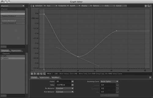
Hermite splines have tangent control handles that allow you to control the shape of a curve. Figure 6.49 shows a sequence of three keyframes with Hermite splines added to the middle keyframe. Its handles are adjusted.
Figure 6.49. Hermite splines are added to the middle keyframe. These splines offer more control than regular TCB splines.
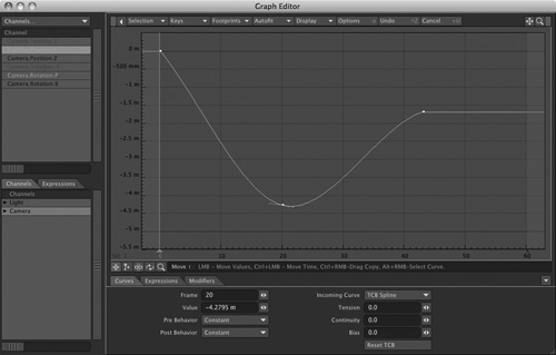
Figure 6.49 shows three keyframes—one high, one low, and one high again—in a sort of bell shape. However, the middle keyframe has a Hermite spline applied and the left handle of it has been pulled down quite a bit. The figure shows how an adjustment to one keyframe can have a drastic effect on the shape of a curve. You can do this by clicking and dragging the small purple handles that appear on a selected keyframe after the spline is added.
If you apply a Bezier curve, you acquire a different type of control than for a Hermite spline. A Bezier spline is a variant of a Hermite spline and also shapes the curve. Figure 6.50 (on the next page) shows the same bell curve of three keyframes with one handle of the Bezier curve pulled down drastically.
Figure 6.50. Bezier splines, although a variant of Hermite splines, work when the next key is also set to Bezier.
Stepped Transitions
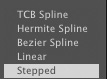
Using a stepped transition for an incoming curve simply keeps a curve’s value constant and abruptly jumps to the next keyframe. Figure 6.51 shows three keyframes similar to those in Figure 6.50, but with a stepped transition applied.
Figure 6.51. Stepped transitions for curves abruptly change your motion from one keyframe to the next.
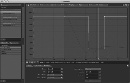
Stepped curves are usable when you want to make drastic value changes between keyframes for situations such as lightning, interference, or blinking lights. You might also find that applying stepped transitions works well for pose-to-pose character animation at times.
Whether you create motions in the Graph Editor or simply adjust preexisting ones, you should understand the amount of control the Graph Editor gives you. The Graph Editor in LightWave 10 even enables you to mix and match spline types for individual channels. Follow along with this next exercise to make and adjust curves in the Graph Editor. Although you have many options for curve control in LightWave’s Graph Editor, using the Tension, Continuity, and Bias (TCB) controls can provide the most natural motion for your animations.
Press o in the Graph Editor to open the General Options tab of the Graph Editor Options panel. Here, you can set Default Incoming Curve values as well as other default parameters (Figure 6.52).
Figure 6.52. You can define the Default Incoming Curve in the General Options tab of the Graph Editor Options panel. Press o to access this panel.
Note
By default, the Graph Editor opens with your currently selected Layout item’s channels already entered into the Channel Bin. You can leave the Graph Editor open while you work, but if you want to have additional item channels to edit, you need to manually bring them into the Channel Bin. However, if you press Shift+G, the Graph Editor is updated with the currently selected item in Layout. What’s more, you can turn on Track Item Selections from the General Options panel of the Graph Editor.
Exercise 6.9. Creating and Adjusting Curves
Start by saving anything you’ve been working on in Layout and then clear the scene. These next few steps provide the information to create curves and adjust them so that certain areas match perfectly. These techniques can be used with any of your projects.
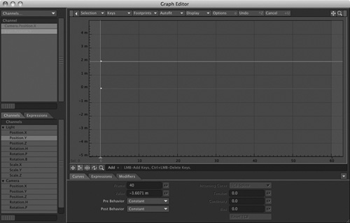
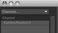
- Open the Graph Editor, and in the Scene Display, double-click the Position.Y channel for the camera.
The Camera’s Y position is now added to the Curve Bin, and your Graph Editor interface should look like Figure 6.53.
Figure 6.53. Double-clicking the camera’s Y position channel adds it to the Curve Bin.
- Expand the channels for the light in the Scene Display by clicking the small white triangle.
- Hold down the Shift key and double-click the light’s Position.Y channel to add it to the Curve Bin. If you don’t hold the Shift key while double-clicking, the new selection overrides anything already added to the Curve Bin.
- In the Curve Bin, hold down the Shift key and select both the Camera. Position.Y and Light.Position.Y channels. Or, hold Control and press the up arrow on your keyboard.
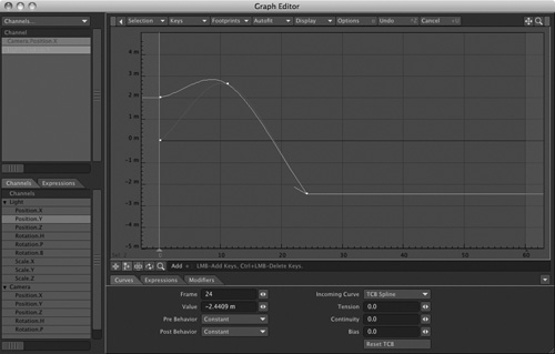
- Select Add mode, and in the Curve Window, create three keyframes to the right of the first keyframe at zero. Figure 6.54 shows the Graph Editor with the additional keyframes.
Figure 6.54. With multiple curves selected, you can create identical keyframes for both channels at once.
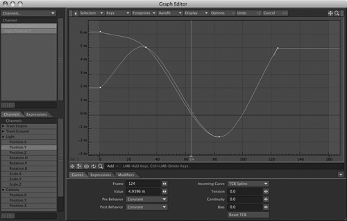
- Select just the Camera.Position.Y channel in the Curve Bin. This automatically deselects the Light.Position.Z channel.
- Select Move mode and move up the last keyframe.
You’ll see the Light.Position.Y channel in the background. You’ve created similar motions on the Y-axis for both the camera and light, but toward the end of the motion, the value has changed. Figure 6.55 shows the adjusted channel.
Figure 6.55. One keyframe in a pair of matching channels is adjusted.
Note
When modifying identical channels on one keyframe, you need to compensate surrounding keyframes slightly. Because of the spline curves, one keyframe affects another.
A more realistic example of matching curves is a formation of flying jets. Each jet flies in unison, swooping, looping, and twisting in perfect sync. After the formation, one or two jets might need to fly off from the pack. Using the preceding example, you can easily select the appropriate channel and adjust the value at the desired keyframe.
It’s easy to see where you would move the jet in Layout, but in the Graph Editor, translating the visual motion to a value might take a little more work. Don’t worry; this next exercise helps you adjust values in the Graph Editor.
Editing Color Channels
Everything discussed in this chapter with respect to object position and rotation also applies to settings such as light intensity, object dissolves, and much more. Let’s look at LightWave Graph Editor’s ability to animate color channels, which is really cool for animating such things as stage lighting or a gradually changing sunset.
Exercise 6.10. Animating Color Channels
- Close the Graph Editor, clear the LightWave scene, and then select the scene’s default light by selecting the Lights button at the bottom of the LightWave Layout interface.
- Press p to enter the light’s Properties panel. You can also get to the Properties panel by clicking the Properties button at the bottom of Layout.
You will see a series of small buttons labeled E. As mentioned earlier, these let you access envelopes, meaning their accompanying values can be animated—changed automatically over time, in the course of an animation. Anywhere you see them throughout LightWave, they will guide you right back to the Graph Editor. However, when you access the Graph Editor in this manner, you have control over only the specific area from which you have selected an envelope, such as Light Color.
It’s important to note that entering the Graph Editor by using the E buttons tells LightWave that you want to perform a specific function. For example, if you click the E button next to Light Color, you’re telling LightWave that you want to animate the Light Color, and the Graph Editor opens accordingly. Entering the Graph Editor on its own from the Layout interface would not enable you to animate the Light Color initially. After you’ve entered the Graph Editor using any E button, the value you enter remains there until you clear it. Therefore, you need to enter the Graph Editor from particular E buttons only once.
- Click the E button next to Light Color, as shown in Figure 6.56.
Figure 6.56. The E (Envelope) button guides you to the Graph Editor for specific control over Light Color.
After you’ve clicked the E button, the Graph Editor panel opens. It looks essentially the same as when you used it earlier this chapter, but now there’s a strip of color along its bottom edge. LightWave enables you to use the Graph Editor’s capabilities on color channels as well as motion channels. Figure 6.57 shows the Graph Editor with the color channel.
Figure 6.57. By clicking the E button for Light Color, the RGB values are now added to the Curve Bin and available for animation.
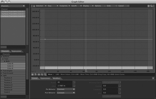
In Figure 6.57, the Curve Bin doesn’t show position, rotation, or scale channels, but rather color channels.
- Select a color channel, such as Light.Color.G, for the green color value. You can also select all color channels at once if you like. By default, though, they should all be selected as soon as you click the E button.
- Create a few keyframes in the Curve Window as you’ve done previously in this chapter. Then, right-click one of the keyframe points and choose Open Color Picker.
Use the system’s standard color picker to choose a new color for the keyframe. Figure 6.58 shows what just one color channel looks like after it’s been adjusted.
Figure 6.58. Scaling the value for a particular RGB color channel changes the color channel for a set keyframe.
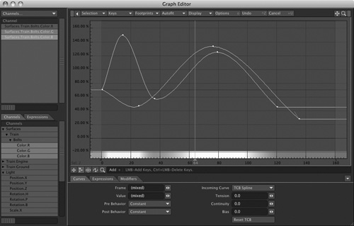
- You can change the value of a key as well. From the Curves tab at the bottom of the Graph Editor, adjust the value and watch how the curve changes.
You’ll see the color you’ve selected appear as a gradual change in the Curve Window.
- Set colors for the other keyframes and adjust their values accordingly to set precise timing. Experiment with these values to see the different types of results you can achieve.
You can cycle colors like this for lights, backgrounds, textures, just about anything! And all this goes back to one thing—timing! Cycling lights is cool, but if you master the timing and keyframing aspects of animation, you can make your lights dance!
The Next Step
So there you have it—keyframing, timing, splines, curves, motions, and the Graph Editor in Layout. While the Graph Editor is a home base for your animations and envelopes, it’s not always necessary for putting objects in motion. When you want more control, or need to animate color values, intensities, and more, the Graph Editor is the way to do it.
Before long, you’ll be setting up motions without even thinking about it. At times, you’ll be able to create full animations without using the Graph Editor; other times, you’ll keep it open while you work. Try using the Selection drop-down list above the Curve Window to access more control over your keyframes. LightWave’s panels are nonmodal, which means that you don’t have to be in a certain “mode” to keep them open. Additionally, you can shrink the size of Layout and configure your computer screen to show Layout, the Graph Editor, and even the Surface Editor all at once. Remember that you can collapse the left side and lower portion of the Graph Editor to reveal just the Curve Window, too.
Don’t let motions, keyframing, and the Graph Editor overwhelm you. A good way to work is to use traditional keyframing methods directly in Layout so that you can see what you’re doing, and then use the Graph Editor for tweaking and adjustments. As with much of LightWave, you have multiple ways to achieve the same result. Refer to this chapter any time you need to control your keyframes with splines or specific modifiers or when you need specific control over individual channels. You’ll find yourself using the Graph Editor for adjusting timing, clearing motions, saving motions, creating object dissolves, or animating color channels more often than you think. Practice creating, cutting, and adjusting keyframes and channels in the Graph Editor. Just remember one thing—save often! Save in increments so you can always take a step back!