
Chapter 6
Advanced ZSphere Techniques
The ZSphere was introduced in Chapter 4, where you saw how it can be used to create a basic armature for a dragon’s body. In this chapter, you’ll see how the ZSphere is actually an extremely versatile tool. In a sense, it’s the Swiss army knife of ZBrush tools because it can be used not only to generate meshes but also as a tool for editing topology, deforming meshes, posing, and rigging characters.
This chapter demonstrates the many ways ZBrush can be used when sculpting a project. You’ll also learn about the Curve brush and some of the ways it can be used to create mechanical pieces.
This chapter includes the following topics:
- Retopologizing a character
- Transferring details using projection
- Deforming a mesh with ZSpheres
- Rigging with ZSpheres
- ZSphere mannequins
- Curve brushes
Retopologizing a Character
So far in this book we’ve talked a lot about creating sculpting-friendly topologies using unified meshing. This was introduced in Chapter 3. A unified mesh is made up of uniformly sized polygons that are evenly distributed across the surface. This type of mesh is very easy to sculpt. However, sometimes you may need a mesh that is better suited for other purposes, such as animation in other 3D packages. Or, you may want to redistribute the polygons more efficiently across the surface. You may want a mesh where some areas, such as a character’s face, have more polygons than other areas, such as the legs, where you can have fewer polygons. This is when retopology becomes a very useful technique.
Retopology is a process where a new mesh is created one polygon at a time using an existing mesh as a template. The details sculpted into the template mesh can then be projected onto the retopologized version. Then sculpting can continue using the retopologized version, or it can be exported and used in another 3D application for animation or other purposes.
ZSphere Retopology
Retopology in ZBrush is achieved through the use of ZSpheres. Essentially, you draw a cage of ZSpheres around the surface you want to retopologize. It’s like connecting the dots in 3D. The ZSpheres are then converted into an adaptive skin, which is an entirely new, sculptable mesh that has the shape of your original object but with a different topology.
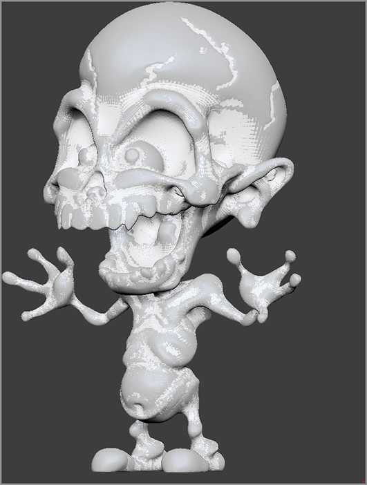
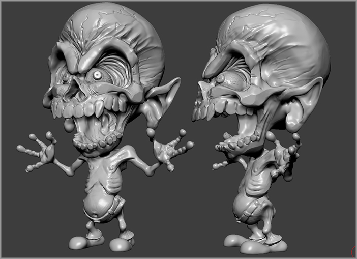
Figure 6-1: The finished dragster-monster sculpt
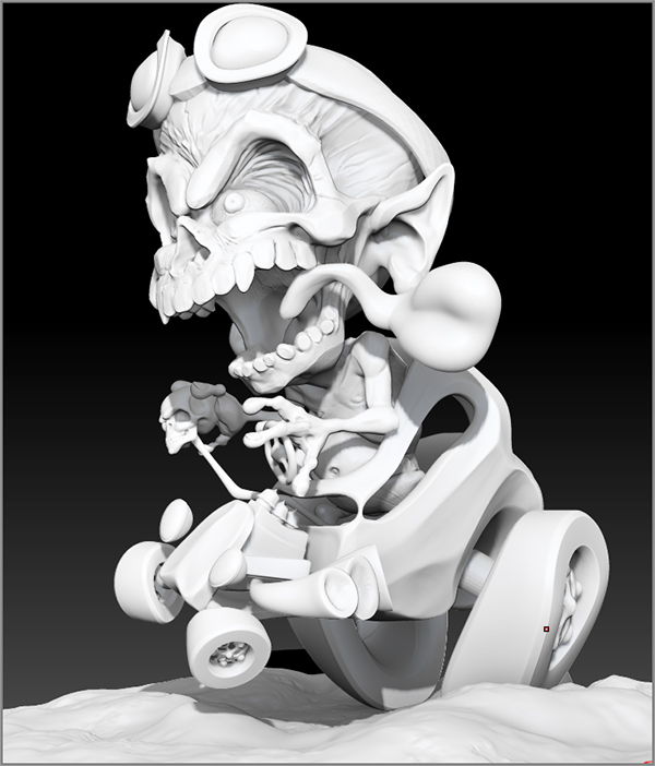
In this example, you’ll see a fairly typical workflow for retopologizing a character mesh. This character has been designed as a cartoon-style demon reminiscent of the monster art/dragster style of artists such as Ed Roth, Bill Campbell, and “Dirty Donny.” Figure 6-1 shows the finished sculpt. I like this style because it’s fun, very loose, and completely different from what I usually do. Experimenting with a variety of styles is always good for an artist.
This demonstration shows some of the techniques I used in creating, sculpting, and retopologizing the character. Even though the style is cartoon, these techniques can be used on any mesh style from simplistic to fantastic to hyper-realistic.
The Basic Character Mesh
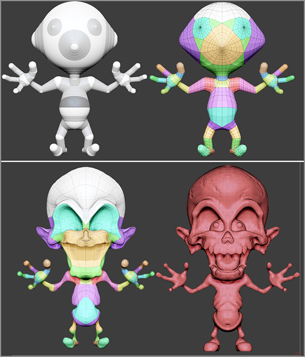
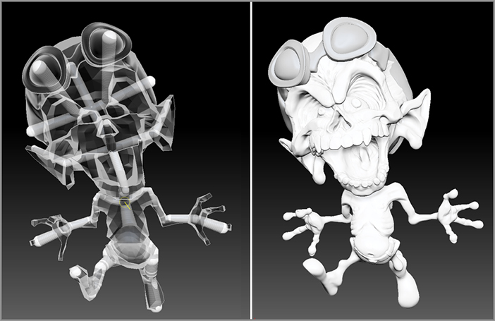
The character for this piece was started using basic ZSphere modeling techniques, as shown in the upper left of Figure 6-2. I converted the ZSpheres into an adaptive skin (Figure 6-2, upper right) and then used the sculpting brushes to work out the basic shape (Figure 6-2, lower left). Then I activated Dynamesh and refined the forms a little more (Figure 6-2, bottom right). These techniques are the same ones you used in Chapter 3 to sculpt the dragon and model the dragon’s body.
You can retopologize any type of mesh; it doesn’t matter if it’s an adaptive skin created from ZSpheres, a Dynamesh object, a parametric primitive, or even a mesh created in a different program and imported as an OBJ file.
Figure 6-2: This basic character is created using ZSpheres and then refining the forms using the sculpting brushes and Dynamesh.
Personally, I prefer to retopologize a model when I feel like it’s about 60 percent sculpted. Then I use retopology to create more polygons in the areas I think need more detail in the final mesh, usually around the eyes and mouth and other parts of the head. I like to use retopology as a way to introduce edgeflow into the model. Edgeflow means that the edges of the polygons flow along the contours of the surface. Think about the direction of wrinkles or folds in a person’s flesh. The skin wrinkles and folds in the areas that deform the most, indicating the underlying anatomy of the surface. By establishing edgeflow into the topology, you’ll find that characters deform more naturally when animated in other programs and, even if you don’t intend to animate the character, sculpted details look more natural in the areas that stretch and compress.
Retopology with ZSpheres
The process of retopologizing a surface starts with adding a ZSphere to the mesh as a subtool. You can use your own model or the dynameshDemon.ZPR project found in the Chapter 6 folder of the DVD while you follow along.
Figure 6-3: Turn on Edit Topology in the Topology subpalette of the Tool palette.
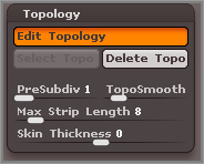
Figure 6-4: Start a polygon by clicking on the head to create the first corner. Click three more times, and then close the polygon by clicking on the first corner again.
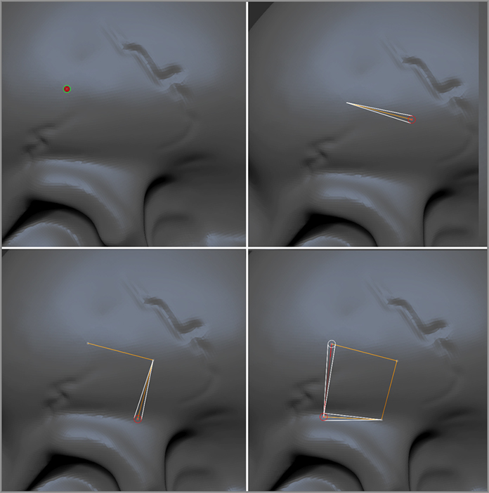
The process of retopology really is like connecting the dots. You simply add vertices to the cage, building out the new topology one vertex at a time.
Figure 6-5: Since Symmetry is turned on, the square is mirrored to the other side of the head.
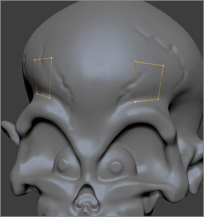
Figure 6-6: Ctrl+click on a vertex to select it, and then add a new line from the selected vertex. Continue to add more squares by connecting more lines to the existing ZSpheres.
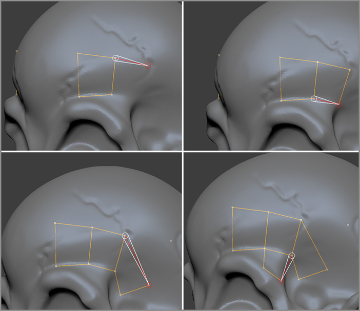
Generally, you want the edges of the squares to flow along the contours of the surface. It’s good practice to stick to four-sided “quads” as much as possible. Avoid making polygons with more than four ZSpheres (known as n-sided polygons, or n-gons).
You can split a row of polygons by clicking on the center of one of the lines that connect the ZSpheres. You can then continue to extend this line by clicking on adjacent lines (see Figure 6-7). Notice that the cursor snaps to even divisions within the line so that you can easily split the line in half or into quarters.
Figure 6-7: Split a row of polygon squares by clicking on the lines between ZSpheres.
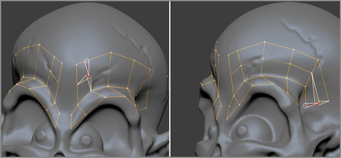
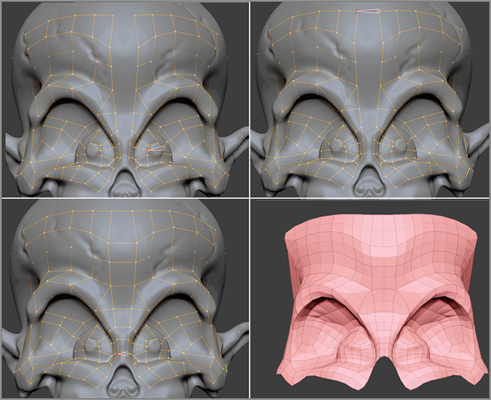
Figure 6-8: Try to use mostly four-sided polygons (quads). Place triangles in less noticeable areas.
If you must add a three-sided polygon (triangle, or “tris”) try to do it in a place that is not terribly noticeable. By following these guidelines you’ll ensure that the topology is clean and easy to sculpt or animate when it’s finished (see Figure 6-8).
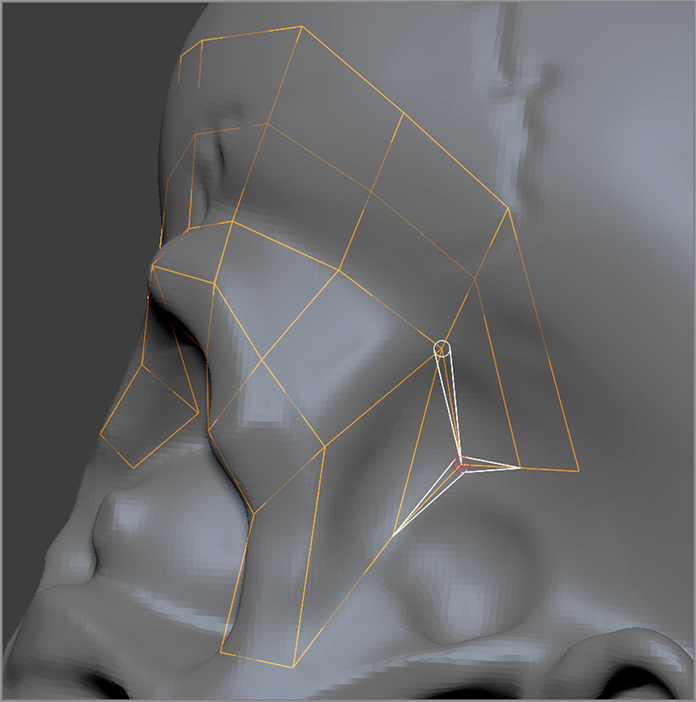
Previewing the New Topology as You Work
As you add more quads to the network, you can preview the retopology by pressing the A hotkey. Follow these steps to preview:
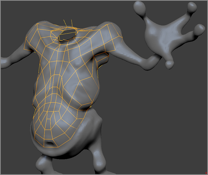
Figure 6-9: Preview the retopology by pressing the A hotkey. The right image shows the topology with the PolyF and Solo buttons activated.
When you have completed the cage, save the project. Figure 6-10 shows the completed retopology cage.
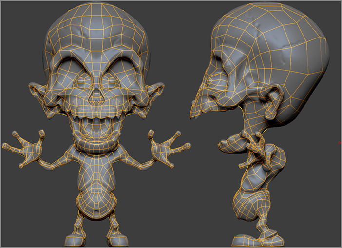
Figure 6-10: The completed retopology cage for the demon character
- You can move a ZSphere by switching to Move mode (hotkey = W) and dragging on the ZSphere. When you move a ZSphere, it will no longer snap to the surface.
- Hold the Alt key and click on a ZSphere (while in Draw mode) to delete it.
- If you make a connection that you don’t want, press Ctrl+Z to undo, and click on a blank part of the canvas (or rotate the view slightly) to deselect the ZSpheres. Click on the model again to add a new ZSphere, and then click on a ZSphere in the network to make a connection.
- Preview the mesh frequently as you work. This is the only way to catch problems ahead of time!
- You can show or hide subtools while working as well as parts of the original model. The ZSpheres will snap to only visible parts of the model.
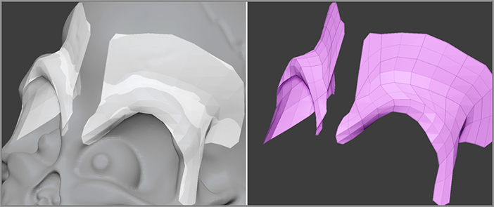
- You can hide parts of the network by holding Ctrl+Shift and dragging over the ZSpheres as well as hiding parts of the template mesh. This can be helpful if the visibility of the network makes it hard to see what’s going on. The following image shows how hiding the head of the original geometry makes it easier to retopologize hard-to-reach parts such as the shoulder.
- Save often and save multiple iterations of the file so you have something to go back to if you mess up!
- If you find that the ZSpheres are behaving strangely, try turning Edit Topology off and then on again. Occasionally when you save and load a project that is midway through the retopology process, ZBrush gets a little confused; this trick usually fixes the problem.
- You can retopologize over multiple subtools at the same time, which will allow you to create a single surface that covers multiple parts. The ZSpheres will snap to any visible subtools.
- While Symmetry is enabled, you can easily retopologize both sides of the surface at the same time. However, creating a line of ZSpheres down the middle of the object can be a bit tricky. It’s usually a good idea to create a pair of lines on either side of the center line, and then disable Symmetry and join the lines together, as shown in the following graphic.
Converting the Retopology Cage to an Adaptive Mesh
Once you have completed the retopology of your model, you will need to convert it into an adaptive mesh. The process is the same for converting a ZSphere armature to a mesh.
Figure 6-11: Click the Make Adaptive Skin button to convert the cage into an adaptive mesh.
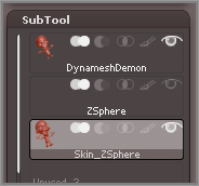
Figure 6-12: Append the Skin_ZSphere tool.
I usually save a version of the project that has the retopology cage as a backup, so once I have deleted the ZSphere tool, I save the project with a different name. This way, if I decide I don’t like something about the retopology later on, I can always go back a version and fix anything I don’t like without having to completely redo the retopology.
Projection
After the surface has been completed, you can easily transfer the details from the original surface to the retopologized version by using projection.
Projecting a Retopologized Surface
ZBrush uses projection, which transfers detail from a source subtool (or subtools) to a target subtool. The topology of the source and the target can be completely different, but the surfaces themselves should be similar in shape for the best results. You can use projection for a variety of sculpting effects; the creative possibilities are endless. One of the more common uses of projection is to transfer details from a source subtool to a retopologized surface.
The following demonstrates how this can be done for the demon model:
The original DynameshDemon will be the source for the projection and the DemonRetopo subtool will be the target. The projection process involves selecting the target subtool, making sure the source subtool (or subtools) is visible, and then clicking the ProjectAll button. The target will shrink to match the source. Usually there’s a little bit of cleanup involved as well, and sometimes it takes a few tries to get it to work right. I find that I get the best results if I project on each SDiv level starting with the lowest level and then working my way up to the highest.
Figure 6-13: Click the ProjectAll button to project the details from the DynameshDemon subtool to the DemonRetopo subtool.
Figure 6-14: After projection, the DemonRetopo subtool matches the shape of the DynameshDemon subtool.
Retopology can take a while to do, but the payoff is usually worth it. I prefer to retopologize my models before sculpting fine detail into the surface. This makes projection easier to deal with. Because I know I will be making changes to the model anyway, I’m not concerned if the projection is not 100 percent perfect. I usually retopologize a model whenever I know that the model will be sent to another program, such as Autodesk® Maya® or modo, for rendering and animation. Or sometimes I retopologize a model if I want to reorganize the mesh to support more detailed sculpting in specific areas such as the face.
ZBrush is not the only way to retopologize a surface, either. There are several solutions from third party software vendors which have more advanced retopology tools. Many of these are easier and faster than ZBrush retopology. I recommend trying Topogun (www.topogun.com) if you expect to be retopologizing surfaces on a daily basis.
After retopologizing the model, I’ll spend some time sculpting details and making changes. I’ll usually subdivide the model a few more times as well.
Figure 6-15: The sculpt of the demon is finished after retopology and projection.
Deforming a Mesh with ZSpheres
Aside from generating sculptable meshes and retopologizing surfaces, ZSpheres can also be used as a deformer. You can create a network, bind it to a mesh, and then as you move the ZSpheres, the mesh can be bent, twisted, and distorted into any shape you like.
And what’s more, you can use the Transpose Master plug-in as a way to use ZSpheres to deform multiple subtools at the same time. There are a few rules you need to follow to ensure that the deformation is smooth and controllable. In this section you’ll see how ZSpheres can be used to deform a hot rod model.
Binding a Mesh with ZSpheres
Before jumping into the hot rod project, this exercise demonstrates the basics of how to bind a mesh to ZSpheres as well as some tips on how to make the process easier.
Figure 6-16: Load the Dog.ztl tool from Light Box.
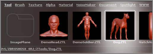
Figure 6-17: Select Dog_1 from the pop-up tool library when you click the Select Mesh button.
Figure 6-18: The dog appears over the ZSphere (left). Move the ZSphere to the pelvis of the dog (right).
Notice that in the SubTool subpalette, there is still just the ZSphere subtool. The dog is in Rigging mode, meaning that it is not a separate subtool; it is combined with the ZSphere while you prepare the rig. The idea here is to build a simple skeleton out of ZSpheres to use to pose the dog.
Figure 6-19: Create a simple armature for the dog.
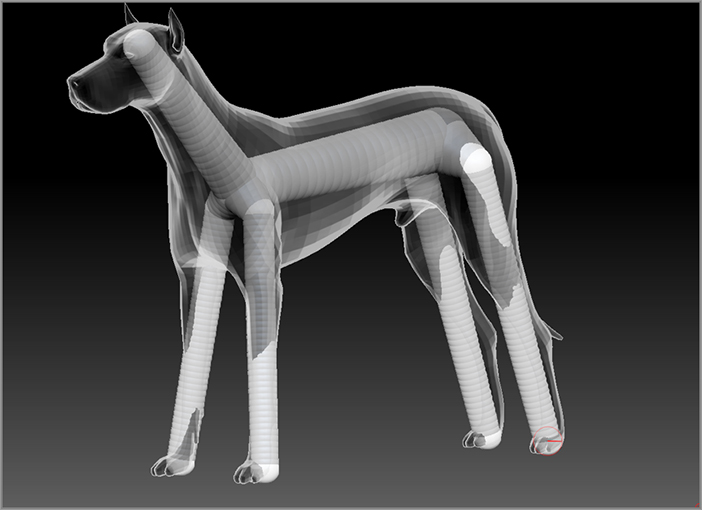
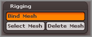
Figure 6-20: Click the Bind Mesh button in the Rigging subpalette.
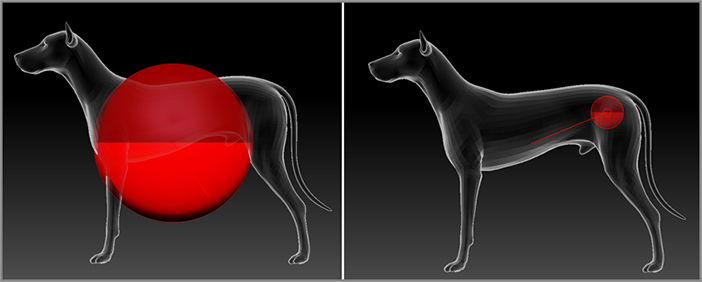
ZSpheres act similar to joints in other 3D applications, such as Maya. However, the system is designed for very simple manipulation, so it is not as sophisticated as an animation rigging system. ZSpheres are bound to the mesh based on proximity alone, so size does not affect how the ZSpheres influence the mesh. This means that sometimes a ZSphere will affect part of the mesh that you don’t want affected. To fix this you need to add some ZSpheres strategically to influence the mesh to be the way you want. This takes practice and some experimentation, depending on the mesh you are trying to rig.
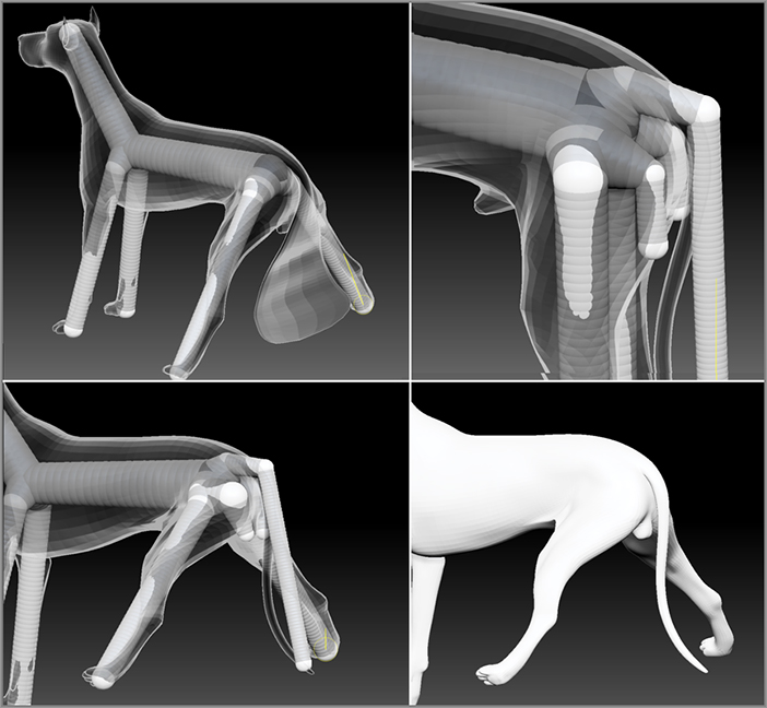
Figure 6-21: The mesh is deformed as the ZSpheres are rotated (upper-left image). The ZSphere armature can be edited (upper-right image), and when the mesh is bound again, the deformation is more precise (lower left). The lower right shows the adaptive mesh.
When you use this technique to deform a mesh, you’ll find that it works best on a model that is not very dense. The deformations are much cleaner and the response is much faster. If you try to deform a mesh made up of a lot of polygons, such as a model in Dynamesh mode, you’ll get a lot of unsightly ripples in the surface that will need to be cleaned up (see Figure 6-22). This is another reason why you may choose to retopologize models you’ve created using ShadowBox or Dynamesh even if you don’t intend to export the model for animation.
Figure 6-22: Using ZSphere rigging on dense meshes can cause ripples in the surface when the ZSpheres are rotated.
Deforming Multiple Subtools with Transpose Master
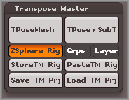
The technique of deforming a mesh with a ZSphere skeleton can also be used to deform a model made up of multiple subtools. This is achieved through the use of the Transpose Master plug-in. When the ZSphere Rig option is activated in Transpose Master, ZBrush will automatically set up a copy of the tool that is set up to be bound to the ZSpheres. Once the deformation is complete, the changes are automatically transferred back to the original and all of its subtools. The example shows how this technique is used to add cartoonish deformations to the hot rod model.
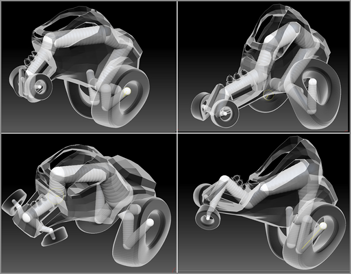
The model was created by retopologizing the ShadowBox car mesh created in Chapter 5. The mesh was then sculpted and the tires and engines were modeled and added as subtools. All of the subtools have multiple levels of subdivision (see Figure 6-23).
Figure 6-23: The hot rod is created by retopologizing and sculpting the ShadowBox hot rod created in Chapter 5.
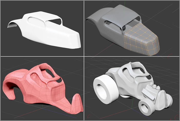
Figure 6-24: Turn on the ZSphere Rig button in the Transpose Master options.
The plug-in now automatically goes through each subtool in the SubTool subpalette and sets it to the lowest SDiv level. Then all the subtools are cloned and merged. This merged, cloned version is placed into the tool library. Then ZBrush automatically selects the ZSphere tool and attaches the merged version of the hot rod. When the plug-in is finished, you have a low-resolution version of the hot rod all set up and ready for rigging (see Figure 6-25).
Figure 6-25: The hot rod model is readied for rigging.
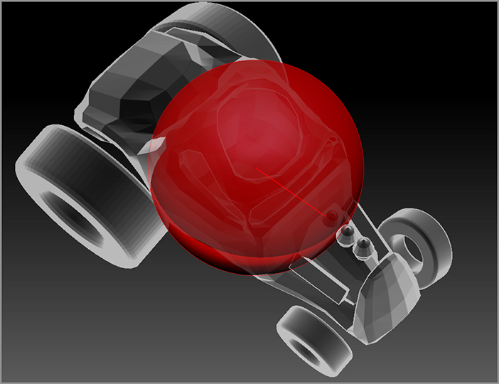
Figure 6-26: The rig is created by adding ZSpheres to the initial ZSphere root.

If you edit the rig significantly, then remember to save the project using the Save TM Prj button in the Transpose Master plug-in!
This technique works really well with cartoony subjects since you can try out new ideas with a good rig that you would not think of otherwise. Figure 6-27 shows a few variations. You can always deactivate Symmetry and see how that affects the deformations you created.
ZBrush will automatically transform the deformations from the copy back to each subtool of the original. The SDiv levels of the original subtools are preserved as well, so you can continue sculpting when it’s done.
Note that the ZSphere rig is deleted in the process of transferring the deformation back to the original. This is why it’s very important to save the transpose project whenever you create a rig you like. That way you can reload it later if you need to change the pose, or you can use it to develop multiple poses for the same character.
ZBrush has become popular as an illustration tool for graphic novels. The ability to use the same rig to come up with many different poses for a character is an indispensible tool for ZBrush graphic novel artists!
Figure 6-27: Variations are created by moving, rotating, and scaling the ZSphere rig.
Posing Characters with ZSpheres and Transpose Master
You can use the same techniques you used to deform the car to pose characters, and this is where Transpose Master really shines (see Figure 6-28). There are a few things to keep in mind when rigging and posing characters using ZSpheres.
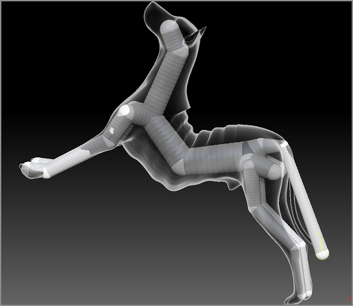
Figure 6-28: A character is rigged and posed using ZSpheres and Transpose Master.
To create better deformations of joints like elbows and knees, place an extra ZSphere before and after the joint ZSphere. In Figure 6-29 you can see how extra ZSpheres were placed on either side of the elbow ZSphere as well as after the shoulder and before the wrist. Try not to go crazy though; too many ZSpheres will make it hard to pose.
Figure 6-29: Extra ZSpheres are placed next to joints to help make a better deformation.
When posing the figure it’s easiest to use Rotate mode and drag on the gray connecting ZSpheres above the joint you want to rotate. To twist a joint, drag directly on the ZSphere.
Move mode allows you to stretch the joints. If you hold the Ctrl key while dragging on the connection ZSpheres, the joint will not stretch; instead, the behavior is similar to Rotate mode.
You can lock a ZSphere by masking it. Simply hold Ctrl and drag a mask over the ZSpheres you want to lock.
Mannequins
The ZSphere mannequin projects that come with ZBrush are a starting place for exploring character poses. Using the mannequins, you can develop poses and multicharacter compositions very quickly and easily without the need to create new ZSphere armatures or to sculpt new models. The mannequins are all set up and ready to pose. What’s more, using Dynamesh you can use the mannequins as a starting point for creating your own unique sculpts.
In the following sections, we’ll take a look at how to create poses with the mannequins, how to create multicharacter scenes, and also how to model the body of a penguin character by remeshing a mannequin.
Posing a Mannequin
A mannequin is simply a premade ZSphere armature. Some of the ZSpheres in the armature have been replaced with simple mesh objects, and the result is something that looks like a mannequin. Several example mannequin projects ship with ZBrush. Let’s open one and look at how it works. Mannequins are useful for creating quick character armatures or for exploring poses as a way to “previsualize” a composition.
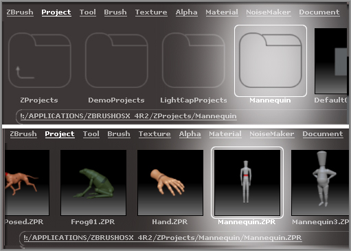
Figure 6-30: Load the Mannequin.ZPR project from the Project folder in Light Box.
The mannequin looks like a gray figure on the canvas. There are several ways you can pose the limbs of the mannequin.
You get the same effect by holding the Ctrl key and dragging on the ZSpheres themselves. If you drag on the ZSphere without holding the Ctrl key, the position of the ZSphere is changed relative to its position in the armature. You can use this technique to reposition the joints of the mannequin (see Figure 6-32).
Figure 6-31: Drag on the forearms to move the arms upward.
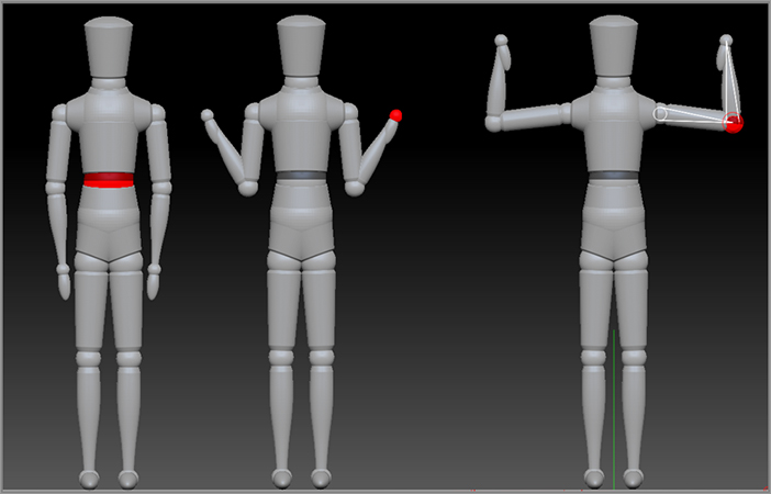
Figure 6-32: Drag on the ZSphere to change the position of a joint.
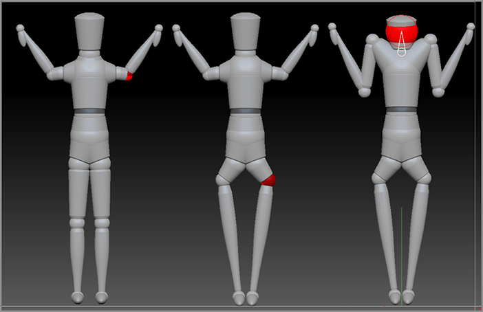
Figure 6-33: Scale mode allows you to change the size of parts of the mannequin.
You can use the Scale mode (hot key = E) to resize parts of the armature. To scale a joint, click and drag on a ZSphere. If you click and drag on the connecting cylinder, you will increase the size of it and all the child ZSpheres and cylinders. Use Alt+drag on the connecting cylinders to make them appear fatter or skinnier (Figure 6-33).
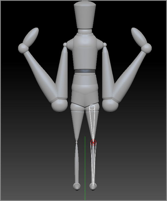
Rotate mode allows you to rotate the ZSpheres by dragging on them. In most cases, it is easier and more intuitive to pose the limbs using Move mode than using Rotate mode.
To move the entire mannequin, switch to Move mode, hold the Ctrl key, and drag on the root ZSphere.
Creating a Multicharacter Scene
In this example, you’ll learn how you can easily create a scene using multiple characters.
Figure 6-34: Select the Mannequin3.ZPR project from Light Box.
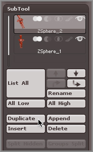
Figure 6-35: Use the Duplicate button to copy the mannequin.
The easiest way to rotate an entire mannequin is to use the Rotate slider in the Deformations palette while the mannequin is at the origin.
Figure 6-36: Turn off the Z button on the Rotate slider, and turn on Y.
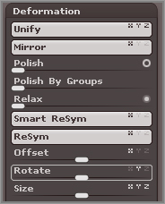
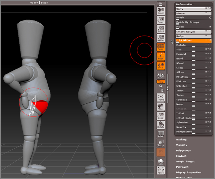
Figure 6-37: Drag the Offset slider to move one mannequin in front of another.
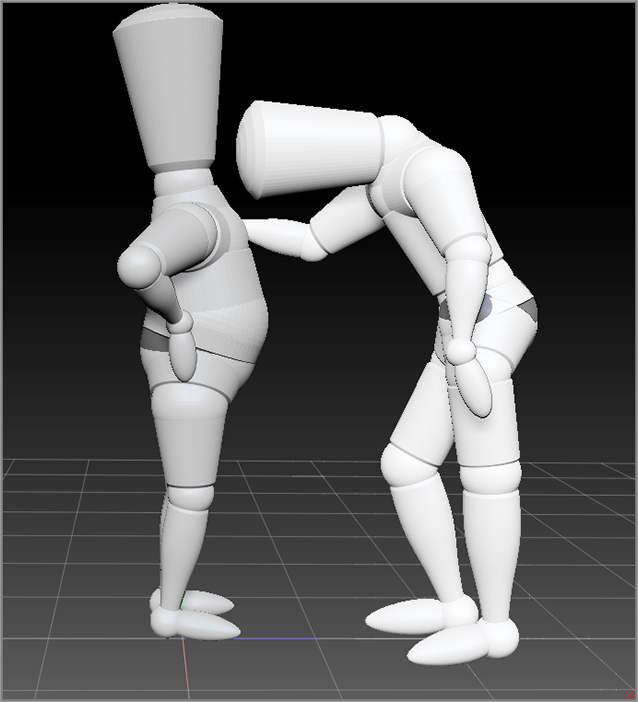
Once the two mannequins are no longer overlapping, you can move them around by holding the Ctrl key and dragging on the root ZSphere.
Figure 6-38: The second mannequin is posed using Move and Scale modes.
Editing a Mannequin
In this section, you’ll learn how you can edit the mannequin to create different types of creatures and characters. These techniques will be applied to creating a penguin model.
Figure 6-39: The arms are edited to look like flippers.
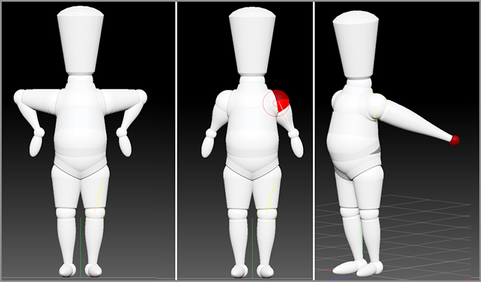
Figure 6-40: The mannequin is edited to resemble a penguin.
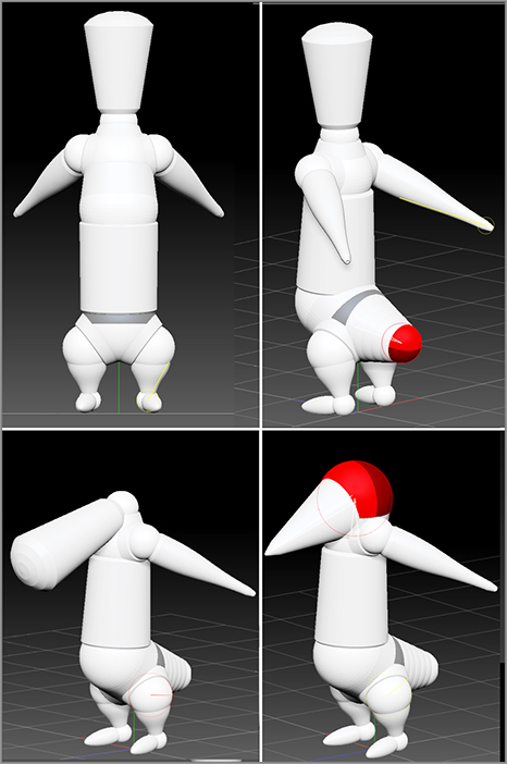
Figure 6-41: Scale the belly and add eyes to the head.
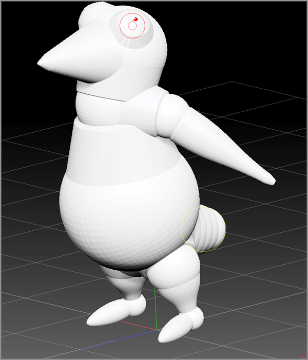
Converting the Mannequin into a Mesh
The next step is to convert the penguin into a mesh, which can then be sculpted. Dynamesh makes this extremely easy.
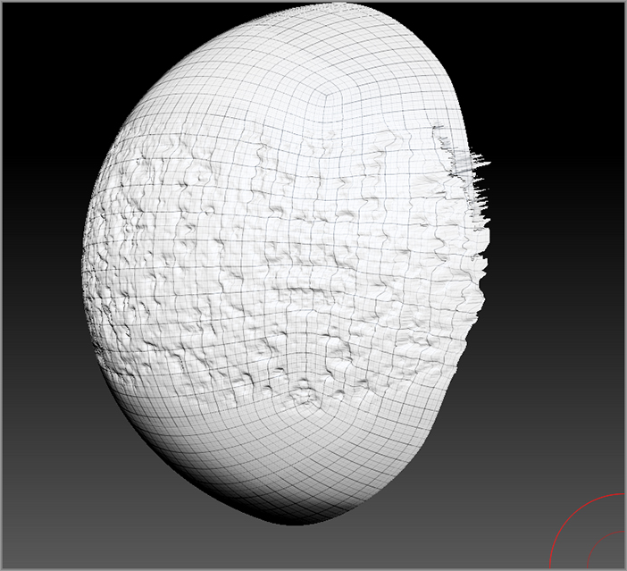
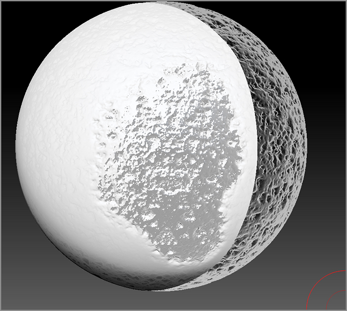
Figure 6-42: The preview shows that the mesh is made up of separate parts (left image). Convert the mesh to a Dynamesh object to make a continuous sculptable mesh (right image).
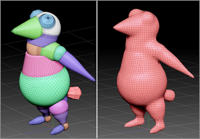
Figure 6-43: The mesh is sculpted into a penguin character.

Curve Brushes
Curve brushes are a subset of the sculpting brushes that allow you to draw a stroke using a curve in 3D space and then manipulate the stroke by pulling and pushing on the segments of the curve. You can use the curve either to insert new geometry into a 3D tool or to manipulate the placement of a stroke after it has been drawn. This increases the flexibility and the precision of the strokes you make in ZBrush.
This section demonstrates how you can use these brushes to add details to a model.
Curve Mode
The Curve brushes are really the same brushes you have been using but with one important difference. These brushes use a special mode called Curve mode, which is activated using the settings in the Transform palette.
Before getting into using this feature in a project, a little background concerning how this mode works would be a good place to start. Let’s try out Curve mode on the Standard brush using a simple surface.
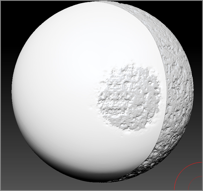
Figure 6-44: Turn on Curve mode in the Stroke palette.
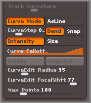
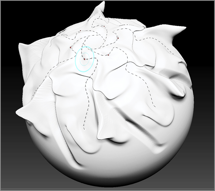
Figure 6-45: Draw a curve across the surface (left image), and then drag the curve to create a bulge (right image).
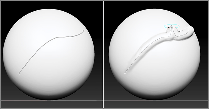
As you continue to drag, the curve around it extends the deformation of the surface. If you draw on another part of the sphere, the deformations are baked into the surface and a new curve is drawn. If you change the Draw Size while the curve is still active, the next time you adjust the curve, the size of the deformation will update automatically.
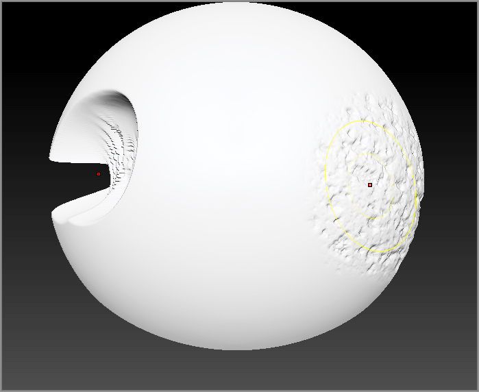
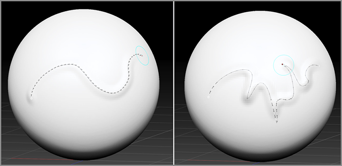
Figure 6-46: Switch to the DragDot stroke type.
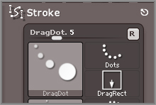
Figure 6-47: The stroke made with the curve can be edited after the curve is drawn.
The options in the Stroke palette let you change the behavior of Curve mode for the current stroke:
Figure 6-48: Stroke mode is enabled for the Move brush, and Radial Symmetry is applied.
Curve mode gives you the power to make some really interesting types of brush strokes. If you look in the Brush palette, you’ll see a number of presets that have Curve mode already applied. These include CurveEditable, CurveStandard, and CurvePinch.
You can turn Curve mode on for almost any type of brush preset. Try activating Curve mode for brushes such as Dam_Standard, ClayBuildup, and Move, and see how this affects the types of marks you can make. See what happens when you use Curve mode together with Radial Symmetry (see Figure 6-48).
In Chapter 8 you’ll see how powerful this option is when used to paint colors on the surface of your model.
CurveTube Brush
Things get truly interesting when you apply Curve mode to the insert mesh type of brush. A number of brush presets combine the power of these options to make it possible to draw out long extruded tubes, create lathed surfaces, and insert rows of bolts and other details. This example shows how these techniques are used to add details to the model of the demon’s cartoon hot rod.
The first thing we’ll do is add some ridiculous-looking exhaust pipes that start from the engine and flare out at the ends. To do this you’ll use the CurveTube brush with a few modifications.
To use any of the curve brushes that insert geometry, you need to have a mesh that has no subtools or a mesh in Dynamesh mode. At the moment all the subtools of this model have subdivisions, and it would be nice to keep them the way they are. So as a workaround, you can append a simple primitive and place it inside the model out of sight. Then you can use the brushes to add the exhaust pipe geometry to the unseen primitive.
Figure 6-49: Append the Sphere3D tool (left image). Use Transpose to scale it down and move it inside the engine block.
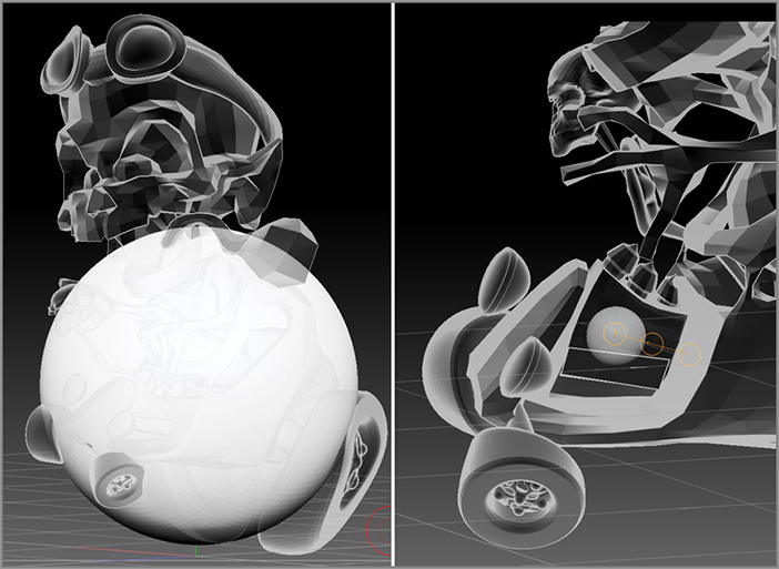
Figure 6-50: Select the CurveTube brush.
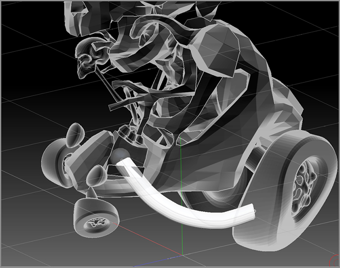
Figure 6-51: Draw a tube from the engine block out into space.
Every time you adjust the Draw Size or the settings in the Stroke palette, the stroke will update the next time you touch the curve. This adds a lot of flexibility to the process because you can change a setting, edit the curve, change another setting, edit the curve again, and continue the process until you have exactly what you want.
Figure 6-52: Shape the extruded tube using the curve (left image).
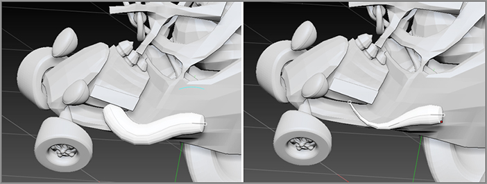
Figure 6-53: Edit the Curve Falloff graph.
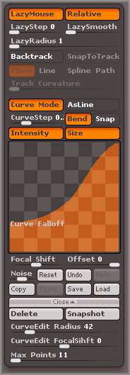
The Curve Falloff graph applies the shape of the graph to whichever point you touch on the curve, so if you touch the start of the curve, then the flare is reversed; if you touch the middle of the curve, then a bulge appears around the center. This odd behavior is actually a neat feature, but it takes getting used to as you shape the curve. If you get frustrated while you’re shaping the curve, simply turn the Size button off in the Stroke palette, adjust the Draw Size, shape the curve, and then turn the Size button back on again in the Stroke palette. Touch the end of the curve and the flare returns.
Figure 6-54: The exhaust pipe is shaped and placed so that it is coming out of the engine.
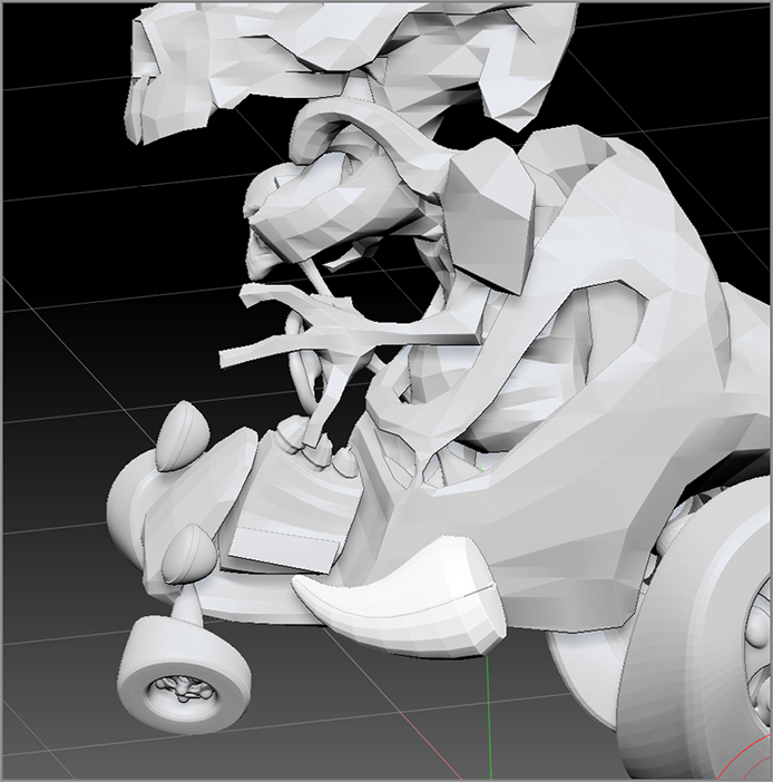
Figure 6-55: Create copies of the pipes by pressing the 5 hotkey.

Creating Wings with the CurveSurface Brush
The CurveSurface brush is another curve brush that allows you to create geometry by drawing out a curve. It differs from the CurveTube brush in that it lofts a surface across multiple curves, making it perfect for making things such as wings. In the demonstration you’ll create some bat wings for the demon character.
Figure 6-56: Append a sphere, and then scale and move it to the back of the demon using Transpose.
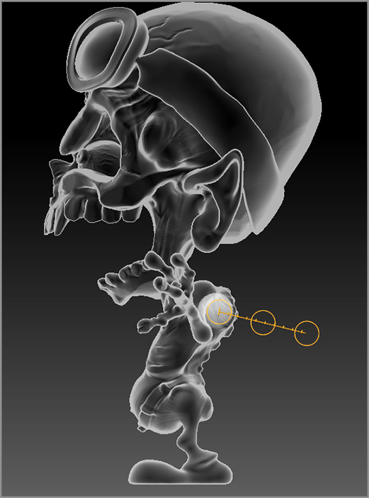
Figure 6-57: Select the CurveSurface brush.

Figure 6-58: As each new curve is drawn, the space between is filled in with a lofted surface.
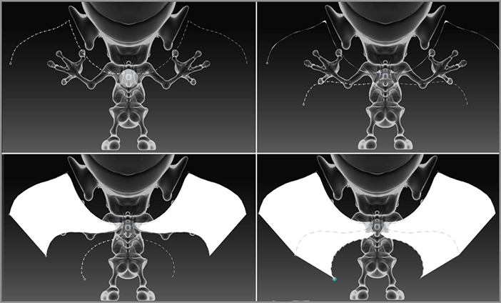
Figure 6-59: Shape the wings by rotating the view and dragging on the curves.
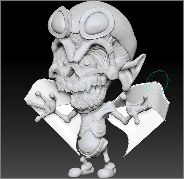
Figure 6-60: Click the Delete button in the Stroke palette to remove the active curves.
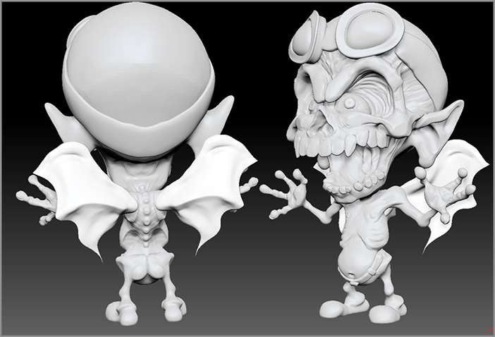
Figure 6-61: The demon character with the wings attached
Summary
In this chapter you learned some more advanced ZSphere techniques. You learned how to retopologize a character using ZSpheres and how to deform a mesh and rig a character using Transpose Master and ZSpheres. You also learned about mannequins and how they can be converted into a sculptable mesh.
In addition, you learned how to use Curve mode for brushes and how to create and edit geometry using the CurveTube and CurveSurface brushes.